Mohamed Tanta
Simulation and Implementation of
Power Electronics for Educational
Purposes - with SEPIC Converter for MPPT
Mohamed Tanta 4 Simulation and Im plement ation of P o w er Electr onics
for Educational Pur
poses - wit h SEPIC Con ver ter for MPPT
Universidade do Minho
Escola de Engenharia
Thesis submitted at the University of Minho
for the degree of Master in
Industrial Electronics and Computer Engineering
Work performed under the supervision of
Professor João Luiz Afonso
Mohamed Tanta
Simulation and Implementation of
Power Electronics for Educational
Purposes - with SEPIC Converter for MPPT
Universidade do Minho
DECLARATION
Mohamed Tanta
E-mail address: [email protected] Telephone: 00351-938419012 Number of Identity:
Title of Thesis:
Simulation and Implementation of Power Electronics for Educational Purposes - with SEPIC Converter for MPPT
Supervisor:
Professor João Luiz Afonso.
Year of completion: 2014
Thesis submitted at the University of Minho for the degree of Master in Industrial Electronics and Computer Engineering.
University of Minho, ___/___/______
To my family, my friends and all of my relatives. To my country Syria, for Portugal and Portuguese people.
Acknowledgements
The completion of the work presented here would not have been possible without the support and the contribution of some people, to whom I send my sincere thanks:
My advisor, Professor João Luiz Afonso for his guidance and persistent help. Your professional and spiritual support helped me to identify and to understand Power Electronics. Thank you for your patience, for countless thoughtful long technical discussions and for your friendly attitude as it has greatly contributed to my professional and personal growth and made it possible to complete this work.
Special thanks for the professors Júlio Martins and Manuel João Sepúlveda for their kindness and excellent comments which helped me to correct many parts of this work.
To my colleagues in the laboratory of GEPE (Group of Energy and Power Electronics).
Dr. José Gabriel Oliveira Pinto for his guidance about the technical management which I used throughout this thesis and without his help, this work will not be completed.
PhD student Eng. Bruno Exposto for his guidance about technical support.
PhD student Eng. Delfim Pedrosa for his guidance in hardware materials that were used in this project.
Eng. Raul Almeida.
To my friends, research fellows.
Employees Carlos Torres, Joel Almeida and Angela Macedo who, as technical workshops of the Department of Industrial Electronics.
To all students who took the master's thesis in Power Electronics Laboratory, respect the environment and provided friendship.
In the end, special thanks for Program of “Global Platform for Syrian Students” which sponsored by President Jorge Sampaio and other financial institutions.
Abstract
Nowadays, the importance and investments in electricity and renewable energy sources is significantly growing, so that the development and prosperity level of nations are measured accordingly with the strength and the efficiency of the power sector in the country.
Every day, the importance of renewable energy sources in the world is increasing to compensate the growing demand of energy in the future, especially with the global rise in oil prices and the environmental pollution. Therefore, renewable energy sources, such as wind, sun, biomass, waves and tides, will be the energy providers for our planet in the future.
Renewable energy sources are closely linked with power electronics, so that it is not possible to obtain the required electrical power without using semiconductor electronic elements, which have the capability to convert electrical power (for example, rectifiers can convert electrical power from AC to DC and the inverters do exactly the opposite). These elements give sufficient flexibility to control and convert the voltages according to our application, and in function of the load needs.
All of the above indicates the importance of power electronics area in the present time. Therefore, as a part of this project, a tutorial document on power electronics has been written for students and non-specialists who want to learn power electronics and know the basics of this area of Electrical Engineering. This document has an organizing strategy and arrangement in order to facilitate and give motivation for students to study power electronics, trying to provide, as much as possible, simple explanations and figures. Every circuit in this document was simulated by using the programs PSIM and MATLAB, which gives the possibility for students to change the circuit parameters, then monitoring the new results (with this document is made available a CD with the simulations models of the circuits). In addition, it contains worked examples with the most important ideas that must be known for every example. All figures and results of circuits are drawn to facilitate and clarify the figures as much as possible, using a plotting program named KST.
As a practical part of this Master thesis work, which also aims to merge renewable energy sources and power electronics applications, a battery charging system with MPPT circuit was implemented, to be used with a micro wind turbine, which can be employed in a boat in the future. This work used a micro wind turbine with a permanent magnet synchronous generator which converts mechanical energy into electrical energy.
The generator produces AC three-phase voltages that are rectified with an uncontrolled rectifier, PD3, which is then connected to a DC-DC converter (coupled inductor SEPIC converter), used here to increase or decrease the DC voltage value. In the output of the rectifier is used a capacitor to filter the DC voltage. The implemented control method uses a Maximum Power Point Tracker (MPPT), with perturbation and observation algorithm. This algorithm is ideal to use with intermittent wind energy resources. To operate at the optimal power point, the algorithm has to change the duty cycle of the SEPIC. This control was implemented in a microcontroller ARDUINO ATMEGA UNO 328P. All the developed system for energy production was simulated using PSIM program. This allowed to observe the behavior of the system when was used a passive load (resistive load) and an active load (battery).
Finally, with this work I hope to create benefits to my homeland Syria and to my second country, Portugal.
Keywords: SEPIC, Power Electronics, Maximum Power Point Tracker (MPPT), Micro Wind Turbine, Renewable Energy, Education, Simulation, Implementation, ADC, PWM.
Resumo
Hoje em dia, a importância e o investimento na energia elétrica e em fontes de energia renováveis tem uma grande preponderância nas nossas vidas. O grau de prosperidade e o desenvolvimento das nações pode ser aferido através do grau de importância do setor energético no país.
A cada dia que passa, a importância das fontes de energia renováveis aumenta, uma vez que existe uma procura cada vez maior de energia, isto tendo em conta o aumento mundial dos preços de combustível e a poluição ambiental. Tendo em conta isto, as fontes de energia renováveis, tais como o vento, o sol, a biomassa, as ondas e as marés, serão os fornecedores de energia para o nosso planeta num futuro próximo.
As fontes de energia renováveis estão intimamente ligadas com a eletrónica de potência, e não é possível obter a energia elétrica desejada sem usar elementos eletrónicos semicondutores, os quais têm a capacidade de realizar conversões (por exemplo os retificados podem converter tensão CA para CC, e os inversores o oposto). Estes elementos dão flexibilidade suficiente para controlar e converter as tensões de acordo com a nossa aplicação, e conforme a carga.
Tudo o que é referido acima indica a importância da eletrónica de potência nos tempos atuais. Desta forma, como parte deste trabalho de Dissertação de Mestrado, foi escrito um tutorial de eletrónica de potência destinado aos estudantes e aos não-especialistas que querem aprender eletrónica de potência e perceber as bases desta área da Engenharia Eletrotécnica. Este documento apresenta uma certa estratégia e organização facilitadoras e motivadoras para que os alunos venham a estudar eletrónica de potência, contendo, dentro do possível, explicações e figuras simples. Cada circuito apresentado neste documento foi simulado usando os softwares PSIM e MATLAB, sendo oferecida a possibilidade aos estudantes para alterar os parâmetros dos circuitos e observarem os resultados (o documento é acompanhado de um CD com os modelos de simulação). Além disto, o documento contém exemplos trabalhados mostrando os conceitos mais importantes de cada circuito. Todas as figuras e resultados dos circuitos foram desenhados de forma a facilitar a sua compreensão, utilizando um programa designado KST.
Como parte prática deste trabalho, e envolvendo a fusão entre a eletrónica de potência e as aplicações de energias renováveis, foi implementado um circuito carregador de baterias com circuito MPPT, a ser usado com uma turbina micro-eólica, e
turbina com um gerador síncrono de ímanes permanentes que converte a energia mecânica do vento em energia elétrica. O gerador produz tensões CA que necessitam de ser retificadas, e para isso é usado um retificador não controlado, PD3, ligado a um conversor DC-DC (conversor SEPIC com indutância de acoplamento mútuo). O conversor serve para aumentar ou diminuir a tensão de saída. Além disto, o retificador tem na sua saída um condensador de forma a filtrar a tensão. O método de controlo implementado foi um seguidor do ponto de máxima potência (Maximum Power Point Tracker - MPPT). O algoritmo do MPPT usado foi o da perturbação-observação. Este algoritmo é o ideal para utilizar com as fontes de energia intermitentes, como é o caso do vento. Para operar no ponto de máxima potência, o algoritmo tem que mudar constantemente o duty-cycle do conversor SEPIC. Este controlo foi implementado numa placa de desenvolvimento ARDUINO ATMEGA UNO 328P. O sistema para produção de energia desenvolvido foi todo simulado usando o software PSIM. Isto permitiu observar o comportamento desse sistema quando foi colocada na sua saída uma carga passiva (carga resistiva) e uma carga ativa (bateria).
Finalmente, com este trabalho, espero poder trazer benefícios ao meu país natal, a Síria, e ao meu segundo país, Portugal.
Palavras-Chave: SEPIC, Eletrónica de Potência, Rastreador de ponto de máxima potência (MPPT), Turbina micro-eolica, Energias Renováveis, Educação, Simulação, Implementação, ADC, PWM.
List of Contents
Introduction ... 1
CHAPTER 1 The History of Power Electronics ... 1
1.1. The Importance and Needing of New Ways to Learn Power Electronics ... 2
1.2. Implementation of Power Electronics Circuits ... 3
1.3. Motivations ... 4
1.4. Objectives and Contributions ... 4
1.5. Thesis Organization ... 5
1.6. What Exists for Learning Power Electronics ... 7
CHAPTER 2 Introduction ... 7
2.1. Electronic Learning Sources ... 8
2.2. Power Electronics Websites and Interactive Forums ... 8
2.2.1. Video Conferencing and Educational Videos ... 9
2.2.2. Electronic Books which are Provided with Animated Figures ... 10
2.2.3. Special Educational Books Written by the Manufacturer ... 10
2.2.4. Social Network Websites which Include a Content of Interactive Groups ... 11
2.2.5. Traditional Learning Sources ... 12
2.3. Power Electronics Journals ... 12
2.3.1. Traditional Educational Books ... 13
2.3.2. Modeling and Simulation Programs... 14
2.4. Conclusion ... 15
2.5. Theory of Power Electronics Circuits ... 17
CHAPTER 3 Introduction ... 17
3.1. Multi-Purpose Power Electronics Circuit ... 17
3.2. Graetz Bridge (H Bridge) ... 17
3.3. Graetz Bridge Rectifier ... 18
3.3.1. 3.3.1.1. Full controlled Greaetz Bridge Rectifier... 18
3.3.1.2. Half Controlled Symmetrical Graetz Bridge Rectifier ... 20
3.3.1.3. Half Controlled Asymmetrical Graetz Bridge Rectifier ... 21
Graetz Bridge (H Bridge) Chopper ... 23
3.3.2. Graetz Bridge (H Bridge) Inverter ... 26
3.3.3. Three Phase PD3 Dual Converter ... 27
3.4. Three Phase PD3 Cyclo Converter (Frequency Converter) ... 29
3.5. Conclusion ... 31
3.6. Simulation of Power Electronic Circuits ... 33
CHAPTER 4 Introduction ... 33
4.1. Modeling and Simulation Type ... 33
4.2. Simulation Feasibilities and Limits ... 34
4.3. Power Electronics Simulation Programs ... 35
4.4. MATLAB Program ... 35
4.4.1. Powersim Program (PSIM) ... 40
4.4.2. Conclusion ... 45
4.5. Development and Simulation Results of the MPPT System with SEPIC Converter .. 47
CHAPTER 5 Introduction ... 47
5.1. Wind Power Generator ... 47
5.2. Uncontrolled Three-Phase Rectifier Bridge with Condenser ... 53
5.3. SEPIC Converter Design ... 54
5.4. Duty Cycle Values ... 55
5.4.1. Inductors Values ... 55
5.4.2. Capacitors Values ... 57
5.4.3. Selection of Active Components ... 58
5.4.4. Control Process ... 59
5.5. Generation of PWM Pulses with the Possibility of Changing the Duty Cycle ... 61
5.5.1. Read the Input Voltage / current Values (ADC) ... 64
5.5.2. MOSFET Driving Circuit ... 65
5.6. MPPT Control Algorithm ... 65
5.7. Simulation Results Using PSIM ... 68
5.8. Conclusion ... 72 5.9.
Experimental Results of the MPPT System with SEPIC Converter ... 75 CHAPTER 6
Introduction ... 75 6.1.
MOSFET Frequency Response ... 75 6.2.
MPPT Experimental Results ... 77 6.3.
MPPT Experimental Results by Using Passive Load ... 78 6.3.1.
MPPT Implementation Results by Using Active Load (Battery) ... 79 6.3.2.
Comparison between Simulation and Implementation Results ... 82 6.4. Conclusion ... 82 6.5. Conclusion ... 85 CHAPTER 7 Conclusions ... 85 7.1.
Suggestions for Future Works ... 86 7.2.
List of Figures
Figure 1.1 - Power Electronics structure loop. ... 2
Figure 1.2 -Tesla superconducting magnet – CERN [2]. ... 3
Figure 1.3 - Micro wind power application using SEPIC converter. ... 4
Figure 2.1- Some examples of tutorial power electronics websites. ... 9
Figure 2.2 - Video conference system [5]. ... 9
Figure 2.3 - Some of books written by the manufacturer [7] [8]. ... 11
Figure 2.4 – some power electronics journals [9]. ... 13
Figure 3.1 - Graetz bridge feeding points. ... 18
Figure 3.2 - Center tapped transformer with PD2 full controlled bridge. ... 19
Figure 3.3 - PD2 full controlled Graetz rectifier results at . ... 19
Figure 3.4 - PD2 Symmetrical Half-Controlled Bridge. ... 20
Figure 3.5 - Symmetrical Half bridge Results (Inductive load). ... 20
Figure 3.6 - PD3 Asymmetrical Half-Controlled Bridge. ... 22
Figure 3.7 - PD2 Asymmetrical Half-Controlled Bridge Results. ... 22
Figure 3.8 - Full bridge chopper circuit. ... 23
Figure 3.9 - Full bridge chopper results at K . ... 25
Figure 3.10 - work characteristic curves for full bridge chopper. ... 25
Figure 3.11 - Single phase H bridge Inverter circuit. ... 26
Figure 3.12 - Single phase H bridge Inverter results. ... 27
Figure 3.13 - PD3 Dual Converter. ... 28
Figure 3.14 - Relation between firing angles and average output voltage value in Dual converter. ... 28
Figure 3.15 - PD3 Dual Converter Results , . ... 29
Figure 3.16 - Driving mechanism for simple half wave step down Cyclo converter. ... 30
Figure 3.17 - Three phase to single phase Cyclo converter Results... 31
Figure 4.1 - Real time simulator in MATLAB [17]. ... 34
Figure 4.2 - RLC Power Circuit. ... 36
Figure 4.3 - The mathematical model for RLC power circuit. ... 37
Figure 4.4 - Simulation results for a RLC power circuit. ... 38
Figure 4.5 - Three phase rectifier bridge. ... 39
Figure 4.6 - Three phase rectifier bridge results by using Simpowersystem library. ... 39
Figure 4.7 – Three-phase controlled rectifier bridge model using Simpowersystem library. ... 40
Figure 4.8 - PSIM environment [20]. ... 41
Figure 4.9 - PSIM controllers for driving power electronics switches. ... 43
Figure 4.10 – Three-phase controlled rectifier bridge model by using PSIM. ... 44
Figure 4.11 – Three-phase controlled rectifier bridge results by using PSIM. ... 44
Figure 5.1 - The ideal power curve of wind turbine [22]. ... 48
Figure 5.2 - Power coefficient curve as a function with TSR ( ). ... 49
Figure 5.3 - Mechanical power – speed characteristics. ... 50
List of Figures
Figure 5.5 - Permanent magnet synchronous generator. ... 51
Figure 5.6 - SilentWind turbine power curve characteristics [24]. ... 52
Figure 5.7 - Using two single phase rectifiers to obtain three phase rectifier bridge. ... 53
Figure 5.8 - Condenser. ... 53
Figure 5.9 - SEPIC converter equivalent circuit. ... 54
Figure 5.10 - Coupled inductor with mutual inductance. ... 57
Figure 5.11 - Implemented circuit of SEPIC converter. ... 59
Figure 5.12 - ATMEGA UNO 328P board [27]... 60
Figure 5.13 - Phase correct PWM / Phase and frequency correct PWM modes [28]. ... 61
Figure 5.14 - Fast PWM mode using ATMEGA UNO 328P [28]. ... 63
Figure 5.15 - Optical isolation between microcontroller and gate to ground circuit... 65
Figure 5.16 - MOSFET driving circuit. ... 65
Figure 5.17 - MPPT perturbation and observation control method [22]. ... 66
Figure 5.18 - MPPT perturbation and observation flowchart [32]. ... 67
Figure 5.19 - Equivalent circuit of maximum power transfer theory. ... 68
Figure 5.20 - Primary simulation model to test MPPT control. ... 69
Figure 5.21 - MPPT simulation results in case of R RLoad . ... 70
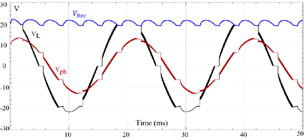
Figure 5.22 – Line and phase voltages of synchronous generator – Rectified voltage. ... 71
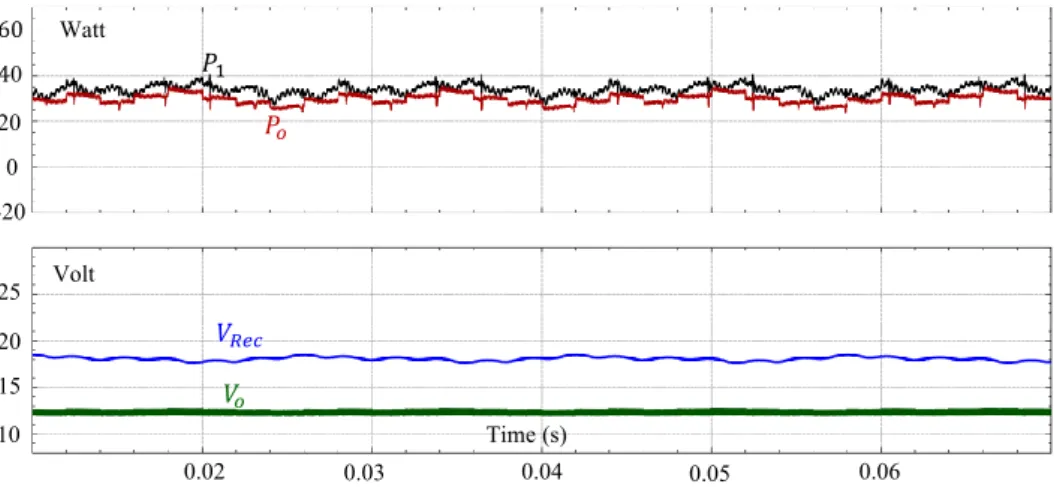
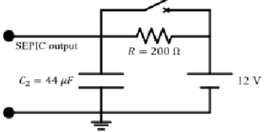
Figure 5.23 - MPPT simulation results in case of 12 V active load. ... 72
Figure 5.24 - charging current of battery result. ... 72
Figure 6.1 - YOKOGAWA digital oscilloscope. ... 76
Figure 6.2 - MOSFET’s response at different PWM frequencies. ... 77
Figure 6.3 - MPPT implementation results by using passive load. ... 79
Figure 6.4 - Protection circuit from high charging current. ... 80
Figure 6.5 - VRLA GEL Battery that is used in the project. ... 80
Figure 6.6 - battery voltage – input voltage of SEPIC - charging current of battery . ... 81
List of Tabels
Table 3.1 - Work mechanism for PD2 Graetz rectifier. ... 19
Table 3.2 - Work mechanism for symmetrical PD2 Graetz rectifier. ... 21
Table 3.3 - Work mechanism for asymmetrical PD2 Graetz rectifier. ... 23
Table 3.4 - Work mechanism for single phase H bridge inverter. ... 26
Table 5.1 - Electrical characteristics for micro wind “SilentWind” [ ] ... 51
Table 5.2 - Mechanical characteristics for micro wind “SilentWind” [ ] ... 51
Table 5.3 - Obtained test results in no – load case. ... 52
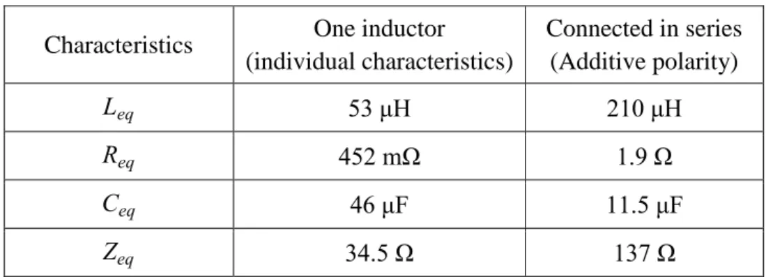
Table 5.4 - Coupled inductor characteristics at 124 KHz frequency. ... 57
Table 5.5 - Choosing fast PWM mode ... 63
List of Abbreviations and Acronyms
PE Power Electronics
ESA European Space Agency
CERN European Council for Nuclear Research
SEPIC Single Ended Primary Inductance Converter
MPPT Maximum Power Point Tracker
PD3 Three-phase rectifier bridge
PD2 Single phase rectifier bridge
HVDC High Voltage Direct Current
SCR Silicon Controlled Rectifier
GTO Gate Turn-Off Thyristor
BJT Bipolar junction Transistor
PWM Pulse Width Modulation
TSR Tip Speed Ratio
EMI Electromagnetic Interference
ICSP In-circuit serial programmer
ADC Analogue to Digital Converter
OTC Optimal Torque Control
P&O Perturbation and Observation
IGBT Insulated Gate Bipolar Transistor
IEEE 1. Institute of Electrical and Electronics Engineers
DSP 2. Digital Signal Processing
Nomenclature
Symbol Meaning Unit
Average output voltage DC voltage – Rectified voltage V
The number of circuit’s branches -
Firing angle of thyristor Degree
Angular frequency Rad/sec
Duty cycle -
Instantaneous value of output voltage V
Electro-motive force V
Frequency, input frequency, output frequency Hz
Resistor
Resistor of Drain-Source junction in turn-on case
Initial speed value m/sec
Final speed value m/sec
Rated speed value m/sec
Radius of turbine blades m
Mechanical torque N.M
Gear ratio between the turbine shaft and the generator rotor shaft -
Pitch angle of the wind turbine Degree
Power coefficient function -
Number of poles pole
Circuit efficiency -
Factor between 20% and 40% -
Rotor swept area m
Air density
Kg m
List of Figures
Peak phase value of source voltage V
Source voltage V
Diode voltage dropping V
Reference voltage V
Peak line-to-line back EMF constant V
RMS input voltage V Inductance H C Capacitor F T Period sec Output DC current A , Source current A , Inductor current A
Inductor ripple current A
Current rating for MOSFET A
Wind turbine output power W
Losses power in MOSFET W
Output power of the rectifier W
CHAPTER 1
Introduction
The History of Power Electronics
1.1.
The amazing evolution in lots of technical fields these days was not achieved without the appearance of electronics and area of electrical engineering at the beginning of the twentieth century which is a continuously renewable field. Nowadays, the world depends more and more on renewable energy applications which are closely linked with Power Electronics (PE) area to convert the type of energy according to the purpose by using rectifiers, choppers, inverters and frequency converters to achieve the demand of global energy. In 1904 and in the same time when Wright brothers built the first plane ever, the British engineer John Ambrose Fleming was working in his modest laboratory to try to make a vacuum glass tube with the ability to pass the current in one direction (Electronic valve) and he actually succeeded to achieve his goal [1].
Nowadays, the effect of Fleming tube invention (electronic valve) on Humans well-being life is not less important than the effect of Wright brothers’ plane invention.
All of PE circuits contain semiconductor elements where the basic purpose of these elements, or electronic valves, is to pass the current in one direction through a small current or voltage value which is applied on the gate pin. This simple function is exploited to do more complex functions and according to this feature, lots of complicated devices and circuits were built to play an important role in people's life. Therefore, the transistor invention was considered as the greatest invention in the twenty century. Consequently, the transistor inventors received a Nobel prize in 1956 even before that its applications started to appear.
In the beginning of 20th century, new applications needing to convert the type of power form AC to DC and the opposite started to appear, so the electronics area was expanded to include PE branch which has many applications in the field of power conversion and transmission.
Nowadays lots of researchers work in the field of optical electronics to study the possibility of manufacturing optical transistors, where the light is the holder of the signals instead of the electrons, and that means increasing the speed of information processing because the transference speed of light is greater than the transference speed of electrons.
Chapter 1 - Introduction
Simulation and Implementation of Power Electronics for Educational Purposes - with SEPIC Converter for MPPT
Mohamed Tanta – University of Minho 2
The importance of PE area in our life needs to find new educational ways to learn PE, especially for academicals students and specialists. The area of PE mainly consists of four blocks as shown in Figure 1.1 and with PE help, it is possible to make a power conversion with high performance and less components volume.
Figure 1.1 - Power Electronics structure loop.
The Importance and Needing of New Ways to Learn Power
1.2.
Electronics
Unfortunately, during the past few years most of the world's energy is generated by traditional ways by burning the fossil fuels and that caused environmental pollution problems, so it was very necessary to find a final solution for this problem by using a renewable energy system which is closely linked with PE applications.
PE deals with converting the type of power according to the final application with the help of semiconductor devices (switchers), so the efficiency of PE circuits can be very high (more than 90%). With advanced technology and low cost of elements, the size became smaller with high and acceptable performance.
PE applications became increasingly important with the appearance of renewable energy system which has environmentally clean resources like wind, solar, hydro, biofuels and wave energy. In addition to that, PE nowadays are used in lots of important fields for example, in the European organization for nuclear research (CERN) which is interested in fundamental structure of the universe, they are using the most complex scientific instruments to study the basics of the matter. Therefore, they need very huge magnetic field values more than earth magnetic value by 100 000 as shown in Figure 1.2 which is produced by using PE.
European Space Agency (ESA) is also using PE to feed and store surplus power in the spacecraft’s batteries until needed [2].
By talking about PE in academicals field, most of students still have difficulties with studying it because some circuits have a complex structure and work mechanism
Chapter 1 - Introduction
like Cyclo converter and Matrix converter. In addition, PE area is closely linked with other fields of Electrical Engineering like Electromagnetics and Electric Machines, so the new ways of presenting PE for students in a simple way to understand and study must be represented in a motivating and organized way with staying faraway from boring mathematical equations which are necessary in some cases. Therefore, as a part of this work, an Educational Power Electronics document, written in a motivating way, is presented for students and for non-specialists to help them to understand PE and develop new ideas in the future. For more information, the chapter 2 in this thesis speaks about the modern ways to learn PE.
Figure 1.2 -Tesla superconducting magnet – CERN [3].
Implementation of Power Electronics Circuits
1.3.
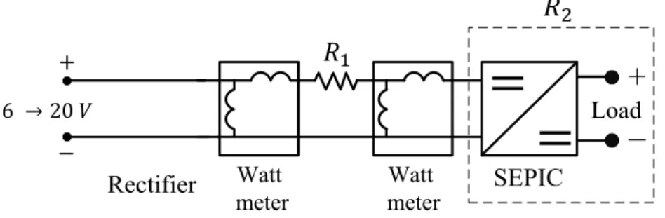
An MPPT (Maximum Power Point Tracker) system for micro wind power using SEPIC (Single-Ended Primary-Inductor Converter) converter has been implemented to be used in boats to charge the batteries, and to observe the differences between simulation results (theoretical results) and practical results (implementation results).
This system contains a micro wind turbine with a synchronous generator, a PD3 (three-phase full bridge rectifier) uncontrolled rectifier bridge and a coupled inductor SEPIC converter to increase or decrease the output voltage (the duty cycle) according to the wind speed. The control method used here, MPPT with perturbation and observation, is controlled by using the microcontroller ATMEGA UNO 328P.
Coupled inductor SEPIC converter is used as a charging system for the batteries. The idea is to drive the boats in two ways through a combustion engine and an electric one. When the combustion engine is working, the wind turbine is connected with synchronous generator to produce AC power which is rectified by PD3 bridge to DC power. The duty cycle of SEPIC is changed according to the input voltage of SEPIC
Chapter 1 - Introduction
Simulation and Implementation of Power Electronics for Educational Purposes - with SEPIC Converter for MPPT
Mohamed Tanta – University of Minho 4
(output voltage of the rectifier) to generate the electricity and charge the batteries, as shown in the diagram of Figure 1.3. This system uses a 450 W wind turbine (SilentWind 24 V) with permanent magnet synchronous generator.
Figure 1.3 - Micro wind power application using SEPIC converter.
This study is a direct application about the relation between Power Electronics converters and what is described in the written Educational Power Electronics document, because this study uses two types of converters, converter (PD3 rectifier) and SEPIC converter (chopper).
Motivations
1.4.
Learning and presenting Power Electronics for the students in a motivating, organized and easy way to study, with the possibility of getting knowledge through simulation results, are the main motivations for this Master thesis work. The implementation of a batteries charging system using a micro wind turbine, with permanent magnet synchronous generator, three-phase uncontrolled rectifier, coupled inductor SEPIC converter, and digital controller, are another important motivation.
Objectives and Contributions
1.5.
The objectives and contributions of this work are the following:
Presenting an Educational Power Electronics document for students with theoretical explanations and with simulations of all the circuits by using PSIM and MATLAB programs.
Providing the models of the simulated circuits on a CD, which gives the possibility to check results and change circuits parameters.
Making a copy of the Educational Power Electronics document in 16:9 dimensions to be used on multimedia devices.
Chapter 1 - Introduction
Implementing a batteries charging system with MPPT for micro wind turbine using a coupled inductor SEPIC converter.
Thesis Organization
1.6.
Chapter 1 is an introduction for the main purpose which gives an idea about needing new motivating ways to learn Power Electronics for the students and the implemented circuits.
Chapter 2 handles the traditional and modern resources to learn Power Electronics these days which includes journals, books, video conferencing and Power Electronics websites.
Chapter 3 handles with Educational Power Electronics document and gives an idea about its content, presentation and multipurpose Power Electronics circuits.
Chapter 4 talking about simulation of Power Electronics circuits, the ways of simulation, MATLAB and PSIM programs.
Chapter 5 describes the theoretical information about micro wind power turbine using SEPIC converter charging batteries system which includes MPPT control, calculation design for SEPIC converter, driving circuit of MOSFET and ATMEGA 328p microcontroller.
Chapter 6 contains the experimental results for the system and also makes a comparison between the theoretical and experimental results for the system.
Chapter 7 contains the conclusion, the problems that should be solved and the suggestions for the future.
CHAPTER 2
WhatExistsforLearningPowerElectronics
Introduction
2.1.
Power Electronics (PE) is in constant innovation and renewal, so the researchers and people who are interested in this field should know always more and more about the fundamentals of electronics and electrical power areas.
As a result of the importance of PE at the present time, there are many educational sources for the people who are interested to learn PE and expand their horizons of knowledge in this field, and because of we are in the age of scientific and technological evolution, both of computer and the internet grid are appeared to use as a trendy methods to get as much information as possible about any subject. In addition to that, the electronics copies of educational books to learn PE which prepared with animated figures are very suitable for students to analyze and recognize very well the work mechanism for any complex circuit, also one of the sources to learn PE is the scientific journals which publish the newest applications of science and the most important scientific achievements. Also we do not have to ignore the role of traditional PE books which are also the primary source to learn PE.
As a result, the available options to study PE can be classified as: 1- Electronic Learning Sources, which are Divided into:
1- PE websites and interactive forums.
2- Video conferencing and educational videos.
3- Electronic books which provided with animated figures. 4- Specific educational books written by the manufacturer.
5- Social network websites which include a content of interactive groups. 2- Traditional Learning Sources, which Divided into:
1- Scientific journals. 2- Traditional books.
Chapter 2 – What Exists for Learning Power Electronics
Simulation and Implementation of Power Electronics for Educational Purposes with SEPIC Converter for MPPT
Mohamed Tanta – University of Minho 8
Electronic Learning Sources
2.2.
Electronic learning nowadays using all of multimedia devices which include lots of available information on the internet grid in different fields to facilitate students realizing for scientific subjects according to their abilities at any time.
The education in age of communication and information technology is a worthy commodity, so it is important these days to realize that we have to deal with education process in a different way from the past, so that is possible today to exchange the information, develop the communication between people, gathering and analysis information to find good solutions for many problems.
Some benefits for electronic educational sources [4]:
1- The big effectiveness for electronic educational sources that increase the ability of learning and recall the information.
2- Less costs and saving more time because of the student does not have to go every day to a university or any educational institute.
3- More flexibility than traditional learning sources which means that the student can access to his educational program at any time.
4- The possibility to choose the level of education, whether for beginner students, professional students or for craftsmen.
Power Electronics Websites and Interactive Forums
2.2.1.
These websites are designed to help people, especially students, job seekers and working engineers who need information about PE completely from the basics to advanced levels. In addition, these websites have forums for discussion about any scientific idea with specialists and experts opinions that will confirm and make the educational process more interesting.
Also one of the features for these websites is they are always constantly in innovation and evolution for the information which fitting with the development of technology. These websites are often associated with researching centers or the universities and they are among the easiest and cheapest ways to study PE.
Some examples for tutorial PE websites, which are completely free, are shown in Figure 2.1.
Chapter 2 – What Exists for Learning Power Electronics
Figure 2.1- Some examples of tutorial power electronics websites.
Video Conferencing and Educational Videos
2.2.2.
The video conference is a broadcasting live lectures from a site to several sites which separated by distances. The process of sending and receiving information will be as an interactive and direct process between members by using the internet grid, cameras and monitors.
This way gives the best opportunity to learn PE for as many people as possible, also one of the most modern applications for video conference which is related to with engineering science is a telemedicine system which allows for doctors to confer or doing some surgical operations through video and robot system [5].
The differences between learning PE through video conference system and normal educational videos is that video conference system is a real time system or synchronous information delivery system as shown in Figure 2.2, while normal educational videos is an asynchronous information delivery system (later time).
Both ways are very preferable to learn PE and any other fields because this way is very interesting and motivating for students, also it helping for reminding the new concepts for a long time more than other ways, in addition of increasing the ability to understand new difficult ideas.
Chapter 2 – What Exists for Learning Power Electronics
Simulation and Implementation of Power Electronics for Educational Purposes with SEPIC Converter for MPPT
Mohamed Tanta – University of Minho 10
Electronic Books which are Provided with Animated Figures
2.2.3.
Animated figures are defined as a group of drawings which are displayed behind each other in sequential mode and regular presentation speed to give at the end a sense of motion on screen, making the learning process interesting and motivating for students to increase the ability of realizing new concepts.
It is possible to give the movement for the most of photos and graphics to clarify most of unclear points or to explain some difficult ideas, so the movement of drawings here gives the motivation for student to learn more and leads to increasing the physical sense for learners, also it can provide this motion accompanied with sounds and clarification texts and in this case will be similar to videos. In PE field, there are lots of circuits with complex work mechanism (for example: cycloconverter and multi-level inverter) that present their work mechanisms in this way leads to simplify the learning process and make easier cognition for students whatever the circuit was complex.
This learning method is still a modern method and has a limited spread comparing with other methods, also most of electronics books which provided with animated figures are not free and expensive but it is possible to find some websites on the internet which provide the explanation for some simple electronic circuits and it is completely free.
Special Educational Books Written by the Manufacturer
2.2.4.
These books are normally written by the company that manufactured the device and the main purpose of these books is to describe and explain about the products, how to use it, and product advantages, so these books are not for a category of beginner students who want to learn the basics in PE. It is more for a category of engineers and specialist people because these books are talking about a specific application and the achievements of company in this field to facilitate product marketing process.
The main features of these books are:
1- Usually these books are accompanied with real clarification figures of products. 2- They includes the designing values of product (datasheet).
3- Explanations about work mechanism and the product installation. 4- Keep up with the last version of product.
5- Most of these books are completely free (download from the company website).
For example: a book about HVDC (High Voltage Direct Current) for beginners and beyond is written by ALSTOM company (ALSTOM is a French multinational
Chapter 2 – What Exists for Learning Power Electronics
company which holds interests in the electricity generation and rail transport markets), so this book is an educational book about specific application (HVDC) and in the same time it aims to marketing the product [7].
Another book from ABB company (ABB is a multinational corporation headquartered in Zurich, Switzerland, operating mainly in robotics and the power and automation technology areas) talking about the solutions for photovoltaic protections as shown in Figure 2.3 [8].
Figure 2.3 – HVDC book written by ALTSOM and Photovoltaic book written by ABB [7] [8].
Social Network Websites which Include a Content of Interactive Groups
2.2.5.
Social websites started recently to spread very rapidly between people and they are known as “the new social media”, which are always in development and in continuous widespread.
These websites are the newest communication technology products and the most popular websites on the internet. Although these websites were established for social communication between people, nowadays they are also being used for scientific activities.
Some of the most famous social websites are Facebook and Twitter, and the first social website in the world is a Facebook with more than 700 million members. It normally consists of some social groups and pages which have specific targets and some of them are specialized about PE with different levels for students.
In this case, the student’s responsibility is only to join for one of these educational groups which talking about PE before being able to discuss in any topic.
Chapter 2 – What Exists for Learning Power Electronics
Simulation and Implementation of Power Electronics for Educational Purposes with SEPIC Converter for MPPT
Mohamed Tanta – University of Minho 12
The features of these websites are:
1- Full possibility to ask any question for members.
2- Speed responding, especially if the group has lots of members. 3- The possibility of discussion about any topic with members. 4- Most of these groups have permanent updating for the information.
The disadvantages of this way to learn PE is a lack of information reliability, by another meaning, the student must be careful to choose the true information when a scientific discussion happens between members because most of those members are not specialized people.
Traditional Learning Sources
2.3.
Every work in this life has positive and negative sides, and that also applying for electronic learning way which depends on computer and internet grid.
The internet grid is an open information system where any user can have his own website which includes lots of inaccurate information and that leads to damage and harm the academic integrity. Therefore, the importance of traditional learning sources which usually are not free and not available for all categories like books and scientific journals that these sources characterized by a full accurate information and still preferable for some people in spite of a widespread of electronic learning sources and that for sure applying for any field of study, including PE. We will talk later in some details about the traditional sources to learn PE.
Power Electronics Journals
2.3.1.
PE journals have two kinds, one of them called educational journals which interested in publishing the recent news and applications of PE area in a simple way for normal people and non-specialists and the second one called academic journals which published for researchers and academic people (specialist people).
Normally, these journals have two published ways, virtual journal contains a collection of previously published paper in a scientific style, and hard copy journal to facilitate its spread between people as much as possible. The headline and the main topics for every copy of this journal are determined by an editorial team according to their relevance. Therefore, it is not necessary that the journal be always restricted to specific topics.
Chapter 2 – What Exists for Learning Power Electronics
Usually most of these journals are not free because it contains lots of innovation and updated information in PE field and some of these academic journals are related to research bodies and the universities around the world, so these journals are not a good choice for people who want to learn the basics in PE but on the opposite, it is a good reference for specialists and researchers.
The advantages of these virtual journals are [9]:
1- Quick access to the previously published papers in a scientific style. 2- Valuable commentary that provided by researchers and academic team. 3- Provide the links for full-text articles and the reference journal.
4- Comfortable browse and links to previous issues.
Some examples of PE academic journal is an International Journal of Advancements in Power Electronics & Digital Devices which includes original research and innovation ideas, applications from all over the world.
Also one of the most important and popular journal in the world is a journal which followed by the Institute of Electrical and Electronics Engineers IEEE as shown in Figure 2.4 which has a lot of various topics (not only about Power Electronics) like bioengineering, robotics, control systems and nuclear engineering.
Figure 2.4 – some power electronics journals [10].
Traditional Educational Books
2.3.2.
The most important option and reference these days to learn PE are still the traditional books which not possible to ignore their roles whatever the other educational methods are developed and increased due to these books contain the feature of information reliability, illustrative examples, and recent studies. The researches
Chapter 2 – What Exists for Learning Power Electronics
Simulation and Implementation of Power Electronics for Educational Purposes with SEPIC Converter for MPPT
Mohamed Tanta – University of Minho 14
nowadays indicated that reading electronics books is harder than reading traditional ones.
Sometimes, the traditional books are more preferable to read for students and researchers, but that does not mean ignoring the electronic learning sources. Despite of the fact that electronic books have recently spread very quickly, but they still need lots of time to eliminate the effect of traditional books which are indispensable for anyone because they supposed as a permanent reference and can be stored for a long time on the opposite of electronic storage tools which can be damaged at any time.
Both traditional and electronic books have their own features. For example, the electronic books can contain animation figures which increase the ability of realizing the new ideas, while the traditional books are more organized, have a logical sequence of ideas, and suitable for all student levels. Also it is important to know that these books are always updated to new editions to avoid old mistakes and keep up with the latest developments in PE, so it can be found the same book of the same author with different editions.
Modeling and Simulation Programs
2.4.
According to these programs, a student can simulate any circuit and detect both of transient and stable results. Usually these programs consist of a dialogic interface with student which allows for student to make a simulation and observe the results before they are applied on reality.
Circuits simulation is a one of the newest way of self-learning PE because it helps the student to predict and conclude the results, on the other hand, usually the simulation is accompanied with the other previous learning ways, for example student can study any circuit and see its work mechanism results before doing the simulation which must to confirm the same results.
Nowadays, lots of simulation programs are available to do the simulation for electrical circuits and the most popular program for simulation and modeling is a MATLAB which consists of lots of libraries and every library is responsible for a specific purpose. Simulink and Simpowersystem libraries are using to simulate Power Electronics circuits and every model could be accompanied with editor file as a definition file to define the variables which including inside the model file.
Also one of the most popular simulation programs is PSIM, and the main feature of this program that it accepts the simulation with C+ language, in order to simulate a
Chapter 2 – What Exists for Learning Power Electronics
microcontroller program. MULTISIM program, from National Instruments company, is also a popular program to make simulations of PE circuits.
Conclusion
2.5.
After making a review about PE learning sources, traditional and modern ones, it is very clear that every option has its own advantages and disadvantages, and that there is no perfect option to learn PE.
The most important point which the student must know is that any information source must be accurate, recommended and reliable, in order to learn PE. Although traditional PE sources are more reliable and trusty, at the same time they can be boring for students, because they usually contain lots of theoretical information and mathematical equations (which in some cases are unnecessary).
In the end, the learner must choose the best option to learn PE according to many points, like his skills and the level of his previous knowledge. Although the traditional ways are typically the slowest ways to understand and remember new ideas, it is not possible to ignore them, because they are references for teaching and learning processes.
CHAPTER 3
TheoryofPowerElectronicsCircuits
Introduction
3.1.
This chapter presents the Educational Power Electronics document, which was prepared in the scope of this Master thesis for students and people who are not specialists in Power Electronics, to make this area of Electrical Engineering as much available as possible. Also, this chapter presents theory of PE circuits, as well as multi-purpose PE circuits that can work in many possibilities, according to the driving way of semiconductor elements.
Multi-Purpose Power Electronics Circuit
3.2.
This chapter gives an idea about the simulation of PE circuits and multi-purposes circuits which described in PE document:
1- converters (Rectifiers) P-PD-S groups.
2- Rectifier groups (ways of linking) Dual converter, 12,18,24 pulse converter.
3- converters (Choppers).
4- converters (Inverters).
5- converters voltage regulators, cycloconverter, and matrix converter.
Inside these five parts there are multi-purpose circuits that can work depending on driving method of semiconductor elements like Graetz bridge or H bridge can work as an rectifier, chopper, or full bridge inverter. In addition, dualconverter and cycloconverter have exactly the same circuit topology but driving method for the elements is completely different.
Graetz Bridge (H Bridge)
3.3.
This bridge is a symmetrical bridge, and Figure 3.1 shows the feeding points for this bridge (A,B for AC side and D,C for DC side) so it can work on three groups of converters:
Chapter 3 – Theory of Power Electronics Circuits
Simulation and Implementation of Power Electronics for Educational Purposes with SEPIC Converter for MPPT
Mohamed Tanta – University of Minho 18
a- Full controlled bridge.
b- Symmetrical half controlled bridge c- Asymmetrical half controlled bridge.
2- converters (Choppers) full bridge chopper.
3- converters (Inverters) full bridge inverter.
Figure 3.1 - Graetz bridge feeding points.
Graetz Bridge Rectifier
3.3.1.
Graetz bridge rectifier could be full controlled (4 SCR – Silicon Controlled Rectifier), half controlled (2 SCR, 2 Diodes) or uncontrolled (4 diodes) depending on the type of semiconductor elements and it is also called full-wave rectifier which convert the whole of the input voltage to DC voltage with the same polarity, to achieve that, we need four semiconductor elements, each two of them work in a half of the cycle (positive and negative one).
3.3.1.1.Full controlled Greaetz Bridge Rectifier
It is possible to change the value of firing angle by using SCRs instead of diodes but to achieve single phase bridge rectifier, it should to create two AC signals with shift angle between them equals to , so using center tapped transformer leads to get double output voltage. Figure 3.2 shows center tapped transformer with PD2 (single-phase rectifier) bridge and Figure 3.3 shows the results at resistive load and firing angle .
Work mechanism for this bridge is completely depending on naturally commutated process between the elements.
The average output voltage is given by the equation:
Chapter 3 – Theory of Power Electronics Circuits
q: number of branches and here q = 2.
: peak value for phase to phase source voltage.
Figure 3.2 - Center tapped transformer with PD2 full controlled bridge.
Figure 3.3 - PD2 full controlled Graetz rectifier results at .
Table 3.1 - Work mechanism for PD2 Graetz rectifier.
The angle
Chapter 3 – Theory of Power Electronics Circuits
Simulation and Implementation of Power Electronics for Educational Purposes with SEPIC Converter for MPPT
Mohamed Tanta – University of Minho 20
3.3.1.2.Half Controlled Symmetrical Graetz Bridge Rectifier
Symmetrical PD2 bridge means that one of load voltage points is always connected to the common cathodes point, which is related to the same type of semiconductor elements and the other load voltage point is always connected to the common anodes point which is also related to the same type of semiconductor elements as shown in Figure 3.4. Therefore, this bridge means that, there are always common anodes or cathodes point which is related to the same type of semiconductor elements.
Work mechanism for this bridge during a half cycle of the positive wave must be in forward bias when also applying trigger pulses or a firing angle on its gate, also diode is still connected during the period . This leads to make a short line between and points especially in the inductive load case as shown in Figure 3.5 [11].
Figure 3.4 - PD2 Symmetrical Half-Controlled Bridge.
Chapter 3 – Theory of Power Electronics Circuits
Consequently, during this period of time and are working together and that leads to make the output voltage value equals to zero. The same process is also repeated between and , so in each cycle there are two short circuit durations. The average value of the output voltage is:
∫
The peak value of output voltage happens when the firing angle , and in this case:
m
Table 3.2 - Work mechanism for symmetrical PD2 Graetz rectifier.
The angle
3.3.1.3.Half Controlled Asymmetrical Graetz Bridge Rectifier
Asymmetrical PD2 bridge means that one of the load voltage points (for example point ) is always connected to the common cathodes point that related to different type of semiconductor elements and the other load voltage point (point ) is always connected to the common anodes point which is also related with a different type of semiconductor elements, so this asymmetrical bridge means that there are always a common anodes or cathodes points which are related with different types of semiconductor elements as shown in Figure 3.6.
Work mechanism for this bridge during the positive half cycle of the wave must be in a forward bias when applying trigger pulses or a firing angle on its gate, and also the diode starts to connect at . That leads to force to stop working, so works just during period . That leads to make a short line between point and during - . Consequently, during this period of time and are working together and that leads to make the output voltage value equals to zero as shown in Figure 3.7. The same process is still repeated, so in each cycle there are two short circuit durations.
Chapter 3 – Theory of Power Electronics Circuits
Simulation and Implementation of Power Electronics for Educational Purposes with SEPIC Converter for MPPT
Mohamed Tanta – University of Minho 22
Figure 3.6 - PD3 Asymmetrical Half-Controlled Bridge.
The Average value of output voltage is:
∫ m m
The max value of output voltage happens when the firing angle , and in this case:
c m c
Chapter 3 – Theory of Power Electronics Circuits
Table 3.3 - Work mechanism for asymmetrical PD2 Graetz rectifier.
The angle
Graetz Bridge (H Bridge) Chopper
3.3.2.
In this case, the source is connected at DC points (D,C points) as shown in Figure 3.8, also the work mechanism has both natural and forced commutation cases. To drive DC machine in four quadrants (both of output voltage and current could be positive or negative), it should to use full bridge chopper or H bridge to run this machine as a motor or a generator (braking) as shown in Figure 3.8, also the main feature of this converter that the output voltage could be totally controlled by the magnitude and the polarity.
Figure 3.8 - Full bridge chopper circuit.
In case of firing the elements during the period , the machine will work as a motor and starts to rotate in clockwise direction (First quadrant) and the bridge works as a buck converter (Step-down chopper) also the elements still in reverse bias state. When switch is disconnected and still works, the current of machine still flows through and the load voltage equals to zero, next if switch is disconnected, the current still flows through and the chopper works in the fourth quadrant (Boost converter).
In case of firing the elements during the period , the machine will work as a motor and starts to rotate in opposite clockwise direction (Third quadrant) and the
Chapter 3 – Theory of Power Electronics Circuits
Simulation and Implementation of Power Electronics for Educational Purposes with SEPIC Converter for MPPT
Mohamed Tanta – University of Minho 24
bridge works as a buck converter (Step-down chopper) also the elements still in reverse bias state. When switch is disconnected and still works, the current of machine still flows through and voltage load equals to zero, next if switch is disconnected the current still flows through and the chopper works in the second quadrant (Boost converter) as shown in Figure 3.9. The average output voltage can be changed by the controlling in duty cycle for each converter but driving process for this full bridge must be integrated process, so .
∫ t ∫ t ∫ ∫
E - When -
- When
- When and the current has a positive value (motor rotates in clockwise direction)or negative value
(braking status) as shown in Figure 3.9.
- When and the current has a positive value (braking status) or negative value (motor rotates in opposite clockwise direction).
Chapter 3 – Theory of Power Electronics Circuits
Figure 3.9 - Full bridge chopper results at .
Figure 3.10 shows the work characteristic curves for full bridge chopper.
Chapter 3 – Theory of Power Electronics Circuits
Simulation and Implementation of Power Electronics for Educational Purposes with SEPIC Converter for MPPT
Mohamed Tanta – University of Minho 26
Graetz Bridge (H Bridge) Inverter
3.3.3.
This bridge consists of two groups of elements , and , connected with DC source E as shown in Figure 3.11. The Single phase H bridge inverter circuit is very similar to the full bridge chopper circuit but the driving method for semiconductor elements is completely different.
By supposing that is a cycle of an alternating voltage, so the angular
velocity is . At both of and are connecting to pass positive
current, then forced to turn off and the current pass through , . Both of and are connecting at until , where to change the RMS and average values of output voltage, the angle takes the values and it is called phase shifting angle to start firing the elements as shown in Figure 3.12.
Figure 3.11 - Single phase H bridge Inverter circuit.
Table 3.4 - Work mechanism for single phase H bridge inverter.
Statues 1 1 1 1 1 1 1 1 1 1 1 1
Chapter 3 – Theory of Power Electronics Circuits
Figure 3.12 - Single phase H bridge Inverter results.
Load current must stay continuous and it has three work cases. Therefore, the first case happens when the current passes through a closed loop like ( equals to zero). The second case happens when the current passes from the source load ( is positive). The third case happens when the current passes from the load source ( is negative).
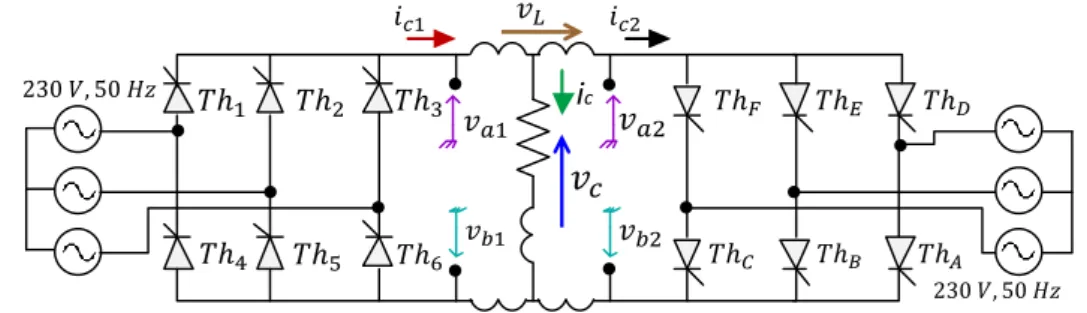
Three Phase PD3 Dualconverter
3.4.
Full controlled converter can work as a rectifier ( or as an inverter ( , but in both cases the power is transferring from AC DC and the direction of power could be changed because the full controlled converter can produce a reversible direct output voltage (with two direction of voltage) but still produces one direction output current, so this dualconverter can work in four quadrants as shown in Figure 3.14 instead of use one bridge with an inverse breaker and it can be used to drive DC machines to work as a motor or a generator.
If two bridges are connected to each other and working together to feed the load with two power directions as shown in Figure 3.13, in this case, it is possible to make a controlling in power flow with two directions depending on which bridge works as a rectifier and the other bridge certainly works as an inverter or in stopping mode. Therefore, There are two types of work mechanism for this dualconverter:
1- Working without circulation current between bridges:
Always one bridge works and the other one stopping (floating mode).
Circulation current: the current passes through two bridges and it is not related to the load current. This current has a big value in normal cases.
Chapter 3 – Theory of Power Electronics Circuits
Simulation and Implementation of Power Electronics for Educational Purposes with SEPIC Converter for MPPT
Mohamed Tanta – University of Minho 28
2- Working with circulation current between bridges:
Always one of the bridges works mainly and the other one works also to receive or send the power. Consequently, these two bridges must work by an integral work system which means the summing of the firing angles for the two bridges is always , for example if the first bridge is working at a firing angle (rectifier mode), the second bridge must work at a firing angle (inverting power mode) [12].
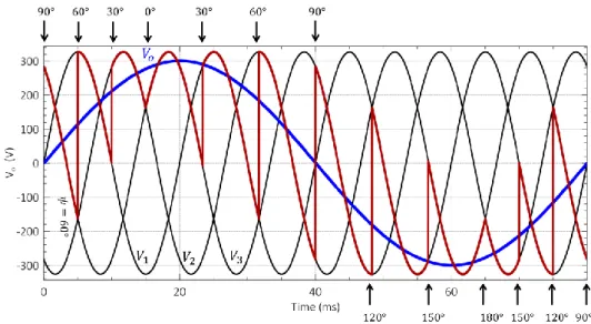
Figure 3.14 shows the relation between the firing angle and the average output voltage value. Figure 3.15 shows the results when bridge A works as a rectifier and bridge B works as an inverter, also the basic task of an inductor is to attenuate the instantaneous differences of voltage values between two bridges. The circulation current
has a value when the voltage of inductor is not equals to zero.
Figure 3.13 - PD3 dualConverter.
Figure 3.14 - Relation between firing angles and average output voltage value in dualconverter.
Chapter 3 – Theory of Power Electronics Circuits
Figure 3.15 - PD3 dualconverter results , .
Three Phase PD3 Cycloconverter (Frequency Converter)
3.5.
It is already known that the dualconverter is capable of passing the load current in any direction after making a control in firing angle for semiconductor elements and also can work in the four quadrants.
The integral equation of firing angles values in dualconverter also possible to apply in cycloconverter (frequency converter) but by making an attention which the firing angle here does not have constant value during all the cycle, so