J. of the Braz. Soc. of Mech. Sci. & Eng. Copyright 2012 by ABCM Special Issue 2012, Vol. XXXIV / 371
Fred Nitzsche
[email protected] Carleton University Mechanical and Aerospace Engineering K1N 6A1 Ottawa, ON, CanadaThe Use of Smart Structures in the
Realization of Effective Semi-Active
Control Systems for Vibration
Reduction
The realization of semi-active actuators by smart structures is discussed. Semi-active actuators have the advantage of consuming much less power than direct-active actuators and are appropriate for the utilization in vibration problems encountered in aeronautical applications, where the loads are in general too high for direct-active actuators to perform. The development of a compact actuator device of this class, from the design phase to the validation tests, is presented.
Keywords: smart structures, piezoelectric elements, semi-active actuators, vibration control of aeronautical structures
Introduction
Current active vibration suppression schemes employing Smart Structures can be classified using two broad categories, including active approaches and semi-active approaches. In direct-active concepts, vibration is controlled using direct, forced action against the vibratory forces. In contrast, semi-active approaches perform vibration suppression using controlled variations of impedance characteristics of dynamic systems.
In the direct-active applications there is a requirement that the actuator must supply large actuation displacements in conjunction with large forces, implicitly implying that large power is necessary. The piezoelectric materials are generally ill suited for this dual performance requirement. In general, such smart material actuators are capable of producing relatively high forces, but possess extremely low stroke capabilities; typically on the order of 50 µm. This restricted deformation capability results either in the need for complex displacement amplification mechanisms (a trade-off only achievable by reducing the actuator force capability) or application of extremely high voltage to obtain the required power to effectively suppress vibrations. In fact, the high-power requirements of the applications using piezoelectric actuators have hindered practical implementations of these concepts in the aeronautical industry due to the typical aerodynamic loads encountered in flight.
One such development was the F-18 fighter vertical fin Buffeting Loading Alleviation (BLA) system (Fig. 1) that has been investigated under the Technical Cooperation Program involving the United States, Canada and Australia, (Nitzsche et al., 2001). Other example following in the same category is the Active Twist Rotor (ATR) program that was developed by NASA and other partners in the United States to reduce vibration in helicopter blades (Wilbur et al., 2002; Shin, Cesnik and Hall, 2005). The trailing-edge flap is another example of direct-active concept under investigation for use in rotorcraft to suppress vibratory hub loads and noise. Contrarily to the former approaches, the latter uses a lumped control method, where actuators are located at a determined location in the structure rather than distributed over its surface. The open- and closed-loop control of a Mach-scaled rotor model with trailing-edge flaps was investigated in wind tunnel (Straub et al., 2001), and more recently a full-scale model was successfully flown by EUROCOPTER (Jaenker et al., 2006).
In semi-active concepts, the vibration is suppressed by modulating the structural properties of a dynamic system such as stiffness, damping or mass. In these approaches, smart materials can be used to perform such modulations in dynamic impedance to suppress vibrations. In contrast to direct-active approaches, the power requirements are relatively low because the actuator forces
are not generated to directly counteract the vibratory forces. In fact, in most devices designed for semi-active control the work done by the actuator forces is independent from the work done by the excitation forces that are the objective of control.
Figure 1. An example of direct-active system: F-18 Fighter instrumented fin with piezoelectric actuators for buffeting control. From Nitzsche et al. (2001).
modulation of the stiffness at the root of a helicopter blade could result in significant reduction of vibration energy at target frequencies (Anusonti-Inthra and Gandhi, 2000).
In this paper, the challenges presented in the design, construction, instrumentation and tests of the semi-active device for application in the reduction of the vibratory loads generated in helicopter rotors are described along with the actual system identification and experimental closed-loop results obtained using a state-switching control algorithm.
Nomenclature
F, f = external force applied to the semi-active actuator k1, k2 = primary, secondary load paths (Fig. 9); secondary,
primary load paths (Fig. 2)
k3 = base-excited system equivalent stiffness N = force applied by piezoelectric actuators ma = hanging mass (piezoelectric actuators) mb, mc = base-excited system mass, controlled mass xa = hanging mass displacement
xb, xc = base-excited system mass, controlled mass displacement t = time
u = control law metric (Eq. (1))
vrel = relative velocity between sleeves (Eq. (1)) Greek Symbols
δ = displacement of semi-active actuator µ, ν = friction coefficient (Fig. 2, Fig. 9) νs,νk = static, dynamic friction coefficient
Design of a Semi-Active Actuator for Structural Control
In Figure 2, two springs, represented by k1 and k2, are attached to opposing rigid walls. The other end of each spring contains a rigidly attached sleeve. The two sleeves mate in the center and can slide with respect to the other. An external (input) force F is applied to the sleeve attached to the spring designated by k2. A stack of piezoelectric actuators is inserted into the internal sleeve attached to the spring designated by k1. When the actuator is “OFF”, the two sleeves can move freely and the resulting horizontal displacement (output) is δ
max = F/k2. Spring k2 is designed to be the primary load path of the semi-active actuator. When the actuator is turned “ON” the stack of piezoelectric yields the internal sleeve causing it to apply a resultant normal force, N, onto the external sleeve.
Figure 2. Sketch of a semi-active actuator for structural control.
A friction force, µN (where µ is the friction coefficient, function of the materials and, in the dynamic case, the relative speed between the two sleeves), is induced by the contact between the two surfaces. If this friction force is sufficiently large the two sleeves are forced into motion together. In this case an arrangement of two springs in series is created and a smaller horizontal output displacement, δmin =
F/(k1+k2) is obtained because the stiffness “seen” by the input force rises from the original k2 to (k1+k2). In fact, the spring designated by k1 is driven by the resultant friction force µN applied by the internal sleeve on the external sleeve, which is controlled by the external electrical stimulus (control input). The latter spring is called the secondary load path of the actuator. Thus, the horizontal output displacement of the system under the input force F varies between the referred two extremes, F/(k1+k2) ≤δ≤F/k2 and the total load is
distributed between the primary and the secondary load paths depending on the sliding characteristics between the two sleeves, which is driven by the friction force, µN, and ultimately by the control force, N. Due to manufacturing tolerances and piezoelectric limitations, the latter two limits may not even be achievable since the maximum stroke supplied by the stack of piezoelectric elements might be insufficient to guarantee that the two sleeves move freely in the actuator “OFF” condition and/or the piezoelectric force is not sufficient to guarantee a locked situation between the two sleeves in the “ON” condition. However, this is not regarded as an important issue because the fundamental concept resides solely on the ability of the system to change in real time its apparent stiffness characteristics. Note that the actuator system also changes its apparent mass because the piezoelectric stack and internal sleeve have inertial properties. However, this effect can be disregarded if the overall system is “stiffness dominated” (i.e., the harmonic disturbance force has a frequency much lower than the internal resonance frequencies of the actuator). The dry friction between the sleeves also creates coulomb damping, which is a fundamental characteristic of the system and in fact adds an important stabilizing effect to the system. Since the actuator actively changes both its apparent mass and stiffness and also its internal damping, it was called an impedance control device.
In the design of such an actuator three major design principles were set to attend the industry concerns, namely: (1) achieve full control controllability – the frequency and amplitude of the control force should be sufficient to control the vibratory loads in a frequency range considered the most important for the vibration of helicopters, which include certain integer multiples of the rotor spinning frequency, 1/rev; (2) achieve full control observability – real-time monitoring of the vibratory loads, displacements and the actuation force should be verified in the same range of frequencies; (3) operate in a fail safe mode – the primary load path of the device should recover its original stiffness characteristics in the event of the failure of power supply, piezoelectric actuators or any other mechanical part.
J. of the Braz. Soc. of Mech. Sci. & Eng. Copyright 2012 by ABCM Special Issue 2012, Vol. XXXIV / 373
the device acts off-center the blade pitch axis and as such it acts as an effective boundary condition at the root with respect to the blade torsional modes (the twist of the blade is resisted by the axial loads passing through the actuator to the swashplate).
Figure 3. Typical installation of the Active or Adaptive Pitch Link (APL) in a helicopter rotor.
Figure 4 shows the time history of the loads transferred through the pitch link according to these simulations. In addition, at 60.3 mm radius for the SHARCS scaled rotor, where the device is to be positioned, the centripetal acceleration is estimated at about 165 g’s and this inertia load was further included in the design requirements.
A picture of the designed semi-active actuator (Active or Adaptive Pitch Link, or APL device) is shown in Fig. 5. In its current design, which is the 3rd generation of this actuator developed at the Rotorcraft Research Group at Carleton University, the overall system stiffness varies between k1 (“soft” link) and k2 (“solid” link), instead of k2 and k1+k2 as shown in Fig. 2. The actuator total mass is 196 g and the eye-to-eye length is 127 mm. The fail-safeness of the actuator is guaranteed because when zero voltage is applied, the “solid” link, original construction is recovered (the applied voltage is used to unlock rather than lock the actuator).
-150 -100 -50 0 50 100
0 50 100 150 200 250 300 350
Azimuth (deg)
P
it
c
h
L
in
k
F
o
rc
e
(
N
)
Figure 4. Design requirements. Maximum pitch link loads over one revolution of the blade. CFD simulations for a forward-flight case with advance ratio 0.28 (rotor collective pitch 5°, logi tudinal cyclic pitch 7°, and laterial cyclic pitch −7°).
Figure 5. Active or Adaptive Pitch Link (APL) device (left). Secondary-path spring components, of 163 kN/m and 256 kN/m (right).
Selecting the soft spring stiffness of the APL is crucial for optimal performance. The APL was designed to control the impedance characteristics of the 1st torsional mode of the blade and, therefore, the stiffness required for the “soft” link mode will be dictated by the structural dynamics of the SHARCS rotating blade to be experimentally measured in later tests. Hence, three secondary springs were manufactured with stiffness ranging from 80 kN/m to 256 kN/m. All experiments outlined in this paper were achieved using the 80 kN/m spring. A Piezomechanik HPSt 150/14-10/50 piezoelectric ring actuator was selected with a maximum block force of 4,500 N, maximum displacement of 45 mm and maximum frequency of 200 Hz. This APL also incorporates a Hall effect sensor (Honeywell, SS495) used in the control law.
Closed-Loop Experiments of the Semi-Active Actuator Designed for Structural Control
Figure 6. Active Pitch Link (APL) dynamic tests apparatus.
Determining the APL capability to change its stiffness was the next objective. Dynamic loading was applied to the APL with a magnitude of 38.5 N at 15.7 Hz. The Hall sensor (i.e. APL spring displacement) data was collected using xPC TargetBox/Simulink™. This data, along with the known magnitude of the input load, was used to create an apparent stiffness curve. The magnitude and frequency of the input load remained constant for the entire test, but the input voltage to the piezoelectric actuator was increased from zero to 150 V in 15 V increments.
0 0.1 0.2 0.3 0.4 0.5
-0.1 0 0.1 0.2 0.3
Time (seconds)
A
P
L
S
p
ri
n
g
D
is
p
la
c
e
m
e
n
t
(m
m
)
Figure 7. Time history of the APL spring displacement (38.5 N axial load and 15.7 Hz frequency) for an actuator control input of 150 V. Tests performed in the rig shown in Fig. 6.
It was determined that the initial conditions of the APL had an effect on the results. Therefore, the tests were done with the APL initially in the soft spring mode (150 V) and then the input voltage to the piezoelectric actuator was decreased to the value for that particular data point. For each piezoelectric input voltage the time history data of the Hall sensor was recorded, as shown for the input voltage of 150 V in Fig. 7.
For each test point the hall sensor (spring displacement) time history data was analyzed to determine the mean displacement, i.e. the average peak displacement per loading cycle over a one second time period. The known input load (38.5 N) was then divided by this displacement to determine the apparent stiffness. The change in APL stiffness for each piezoelectric input voltage is plotted in Fig. 8. Note that no point is plotted for 0 V input to the piezoelectric actuator since the APL at this design condition acts as a solid link and, therefore, the apparent stiffness is infinite. The apparent stiffness curve shows that as the piezoelectric actuator input voltage is increased from 0-60 V the stiffness of the APL changes approximately linearly. At an input voltage greater than 60 V the stiffness of the APL is constant, corresponding to its “soft” link mode value. This stiffness curve demonstrated that the APL had indeed the capability to control stiffness in a roughly proportional way with the input voltage.
As the APL damping characteristics would change in time due to the wear of contacting parts and/or temperature increase, the control algorithm should be able to self-compensate for these
changes. Most importantly, the modal characteristics of the blade first elastic torsion mode shape, especially its frequency (due to the active changes in the APL apparent stiffness) and damping ratio (due to the APL internal friction) must be controllable. For the first time, an on-off closed-loop control law was experimentally implemented with the prototype APL. The selected control law uses as input only the relative velocity between the two sleeves shown in Fig. 2, which is independent from the dynamic friction coefficient. Therefore, there is a degree of self-compensation for the temperature changes and wear of the contact parts in the provided control system, as the piezoelectric elements keep applying normal loads to increase as much as possible the friction between the sleeves in order to decrease the actual relative motion that is detected by the sensor. The control logic also requires an “arrow” input signal from the strain gauges that measure the output load of the APL. This control law reduces the magnitude of the output vibration by extracting kinetic energy from the system (Nitzsche et al., 2005) and works by clamping and unclamping the APL between the “soft” and “solid” link modes.
0 50 100 150
140 150 160 170 180 190
Piezo Actuator Input Voltage (V)
A
P
L
S
ti
ff
n
e
s
s
(
k
N
/m
)
Figure 8. APL apparent stiffness curve.
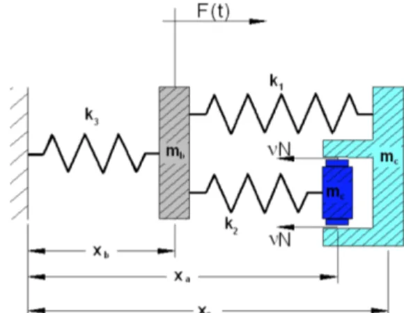
Figure 9 depicts the application of the APL device in the helicopter rotor with the control objective of decreasing the motion associated with the mass, mc (the swashplate). Mass mb and spring k3 simulate the mass and the stiffness of a base-excited system by the external force F. In this particular application, they may be related to the blade effective mass and stiffness and the unsteady aerodynamic force acting on the blade, respectively. Springs k1and k2 are the main and secondary load paths (depicted respectively as k2 and k1 in Fig. 2). In Fig. 9, ν is the dynamic friction coefficient between the two sleeves, function itself of the relative velocity between these two parts, vrel. Hence, if the piezoelectric stack applies a normal force N, νN is the control force.
Figure 9. Base-excited system for the active control algorithm description.
J. of the Braz. Soc. of Mech. Sci. & Eng. Copyright 2012 by ABCM Special Issue 2012, Vol. XXXIV / 375
The control algorithm states that:
(
)
= < > =
= − =
0 u if N
0 u if N
0 u if 0
N
v x x x x u
last max
rel c c a
c & & &
&
(1)
where in Eq. (1) Nmax is the maximum possible normal load applied by the piezoelectric stack at the instantaneous operational conditions (limited by the parts temperature and weariness), and Nlast is the last value of N. The latter value is to avoid the indetermination of the dynamic friction coefficient at its static value, νs (Fig. 10):
Figure 10. Typical variation of the dynamic friction coefficient with the
relative velocity between the two sleeves, vrel.
It is also noticeable that the control algorithm is independent of the frequency, as long as the sampling rate of the control signals is set correspondingly. This was discussed in another publication, where a numerical simulation was performed (Nitzsche et al., 2005). Figure 11, a reproduction from this publication, demonstrates the numerical simulations of the described control algorithm (“state switching”) on the base-excited system presented in Fig. 9. As seen, the control algorithm performed extremely well at a broadband of frequencies of interest (ma = 1.5 kg, mb= 1.0 kg, mc= 11.5 kg, k1 = 13.1 N/mm, k2 = 26.2 N/mm, k3 = 175 N/mm), indicating its robustness.
Figure 11. Numerical performance of the control algorithm (“state switching”) presented in Eq. (1) applied to the base-excited system presented in Fig. 9 (Nitzsche et al., 2005). Chirp signal excitation (500 N peak-to-peak). The DC (direct current) actuation results correspond to the
actuator device locked to its highest stiffness value, kmax = k1 + k2.
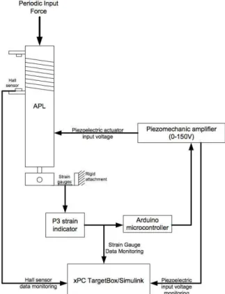
Figure 12. Schematic of the test setup for the closed-loop tests.
0.5 0.6 0.7 0.8 0.9 1 1.1
-0.5 0 0.5 1 1.5 2
Time (seconds)
R
a
w
S
ig
n
a
l
(V
)
P
ie
z
o
I
n
p
u
t
(1
/1
0
0
)V Piezo Input
Output Load Spring Disp.
Figure 13. Closed-loop control test results in the non-rotating APL. Control law turned ON at 0.8 s for an input load of 8.5 N and frequency of 25 Hz.
For the performed closed-loop experiments (schematic shown in Fig. 12), the closed-loop control logic was implemented using an Arduino microcontroller. The strain gauges data were collected in order to monitor the change in the magnitude of the output load of the APL and a Hall sensor was used to measure the relative speed, vrel in Eq. (1). The xPC TargetBox/Simulink™ data system was used to monitor and record the real-time data from the sensors and the input voltage being supplied to the piezoelectric elements. The only output sent from the xPC TargetBox/Simulink™ was the shaker input (periodic force).
at 0.8 seconds, the control law was activated. Typical time-history data of the pitch link loads are shown in Fig. 13. This figure also shows the piezoelectric input voltage, and the spring deflection.
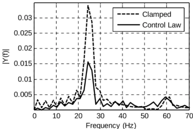
Fast Fourier Transformation (FFT) analysis was used to determine the amount of vibration reduction, shown in Fig. 14. It can be seen that there is a 54%-reduction in the magnitude of the output loads from the APL when the control law is implemented.
The test was repeated for a range of input load frequencies. For each input frequency, the output load reduction due to the control law was tested and analyzed via FFT. Each test was conducted 5 times to verify its consistence. The results in Fig. 15 show the mean reduction in vibration due to the activation of the closed-loop control law for a range of input frequencies. It is interesting to note that the higher the input frequency, the larger the reduction of vibration.
In order to verify the efficiency of the closed-loop control law, the tests were repeated operating the APL in its “soft” link mode, with a constant 150 V input to the actuator. Figure 16 shows that locked in its “soft” mode the APL reduces the magnitude of vibration by about 20%-35%, a value much less than when the closed-loop control law is activated. This effect is due to a verified residual friction between the sleeves that persists at some extent in “soft” link mode when the actuator is unlocked by the application of 150 V and contributes to the pure frictional, passive damping of the system. At 0 V the actuator is locked to its maximum stiffness value, and the level of vibration is given by the “clamped” value shown in Fig. 14.
0 10 20 30 40 50 60 70
0.005 0.01 0.015 0.02 0.025 0.03
Frequency (Hz)
|Y
(f
)|
Clamped Control Law
Figure 14. FFT Analysis of APL output load with an input load of 38.5 N at 25 Hz.
12 14 16 18 20 22 24 26
20 30 40 50 60
Input Load Frequency (Hz)
V
ib
ra
ti
o
n
R
e
d
u
c
ti
o
n
(
%
)
Figure 15. APL vibration reduction as a function of the input frequency with an input load of 38.5 N (control on).
12 14 16 18 20 22 24 26
20 30 40 50 60
Input Load Frequency (Hz)
V
ib
ra
ti
o
n
R
e
d
u
c
ti
o
n
(
%
)
Figure 16. Vibration reduction as a function of input frequency for the “soft” link, pure frictional, passive damping mode of operation of the APL (control off).
Conclusions
The first-ever closed-loop control test results for a semi-active actuator developed for the control of forced aeroelastic response of a rotating wing were presented. The tests confirmed that near to 60% reduction in vibration is achievable using an on-off control algorithm based on the principle of maximum energy extraction.
Acknowledgements
The author would like to acknowledge the major contributions from the members of his Rotorcraft Research Group at Carleton University and Smart Rotor Systems Inc. towards the manufacturing and tests of the APL device presented in this work. In particular, he would like to thank his colleague Assoc. Prof. D. Feszty, his PhD student Mr. K.V. Khomutov, his Master students M. Richardson and R.D. Young, and the engineers Mr. J.A. Pickard and S.B. Vamosi.
References
Anusonti-Inthra, P., and Gandhi, F., 2000, “Helicopter Vibration Reduction through Cyclic Variations in Blade Root Stiffness,” Journal of Smart Material Systems and Structures, Vol. 11, No. 2, pp. 153-166.
Jaenker, J., et al., 2006, “Advanced Piezoelectric Servo-flap System for the Rotor Active Control,” Paper AR-10, Proceedings of the 32nd European
Rotorcraft Forum, Maastricht, The Netherlands.
Nitzsche, F. Grewal, A., and Zimcik, D., 1999, “Structural component having means for cyclically varying its stiffness to control vibrations,” Patent: USA (5,973,440), European Community (EP-996570-B1), and Canada (2,242,214).
Nitzsche, F., Zimcik, D., Ryall, T., Moses, R. and Henderson, D., 2001, “Closed-Loop Control Tests for Vertical Fin Buffeting Alleviation using Strain Actuation,” AIAAJournal of Guidance and Control, Vol. 24, No. 4, pp. 855-857.
Nitzsche, F., Zimcik, D., Wickramasinghe, V. and Yong, C., 2004, “Control Laws for an Active Tuneable Vibration Absorber Designed for Aeroelastic Damping Augmentation,” The Aeronautical Journal of the UK Royal Aeronautical Society, Vol. 108, No. 1079, 2004, pp. 35-42.
Nitzsche, F., Feszty, D., Waechter, D., Bianchi, E., Voutsinas, S., Gennaretti, M., Coppotelli, G., Ghiringhelli, G.L., 2005, “The SHARCS Project: Smart Hybrid Active Rotor Control System for noise and vibration attenuation of helicopter rotor blades,” Paper 052, Proceedings of the 31st
European Rotorcraft Forum, Florence, Italy.
Opoku, D.G., Nitzsche, F., 2005, "Acoustic Validation of a New Code Using Particle Wake Aerodynamics and Geometrically Exact Beam Structural Dynamics", The Aeronautical Journal, Vol. 109, pp. 257-267.
J. of the Braz. Soc. of Mech. Sci. & Eng. Copyright 2012 by ABCM Special Issue 2012, Vol. XXXIV / 377
Oxley, G., Nitzsche, F. and Feszty, D., 2009, “Smart Spring Control of Vibration on Helicopter Blades,” Journal of Aircraft, Vol. 46, No. 2, pp. 692-696.
Shin, S-J, Cesnik, C.E.S., and Hall, S.R., 2005, “Closed-loop Control Test of the NASA/Army/MIT Active Twist Rotor,” Journal of the American Helicopter Society, Vol. 50, No. 2, pp. 178-194.
Straub, F.K., et al., 2001,“Development of a Piezoelectric actuator for Trailing Edge Flap Control of Full Scale Rotor Blades,” Journal of Smart Materials and Structures, Vol. 10, No. 1, pp. 25-34.