Marcelo A. Trindade
[email protected] Department of Mechanical Engineering S˜ao Carlos School of Engineering University of S˜ao Paulo 13566-590 S˜ao Carlos, SP, BrazilAyech Benjeddou
[email protected] Institut Sup´erieur de M´ecanique de Paris LISMMA/Structures 3 rue Fernand Hainault 93407 Saint Ouen, FranceParametric Analysis of Effective Material
Properties of Thickness-Shear
Piezoelectric Macro-Fibre Composites
A previous study on the characterization of effective material properties of a d15 thickness-shear piezoelectric Macro-Fibre Composite (MFC) made of seven layers (Kapton, Acrylic, Electrode, Piezoceramic Fibre and Epoxy Composite, Electrode, Acrylic, Kapton) using a finite element homogenization method has shown that the packaging reduces significantly the shear stiffness of the piezoceramic material and, thus, leads to significantly smaller effective electromechanical coupling coefficient k15 and piezoelectric stress constant e15 when compared to the piezoceramic fibre properties. Therefore, the main objective of this work is to perform a parametric analysis in which the effect of the variations of fibre volume fraction, Epoxy elastic modulus, electrode thickness and active layer thickness on the MFC effective material properties is evaluated. Results indicate that an effective d15 MFC should use relatively thick fibres having relatively high shear modulus and relatively stiff epoxy filler. On the other hand, the electrode thickness does not affect significantly the MFC performance.
Keywords: macro-fibre composites, shear actuators, properties characterization, finite element homogenization method
Introduction
Over the last decade, packaged conformable piezoelectric sensors and actuators have drawn great attention from the research community working on applications such as structural control, structural health monitoring and energy harvesting. For practical and commercial applications, they do possess a number of advantages over the standard monolithic piezoceramic patches, such as a less brittle behaviour and more robust electric connection (Skinner, Newnham and Cross, 1978). Based on the concept of Piezoelectric Fibre Composites (PFC) proposed by Bent and Hagood (1997), who used extruded piezoceramic fibres with circular cross-section embedded to an epoxy-based resin matrix and covered by Copper electrodes and protective Kapton and/or Acrylic layers, the so-called Macro-Fibre Composites (MFC) have become very popular since they combine the conformability of epoxy-matrix composites and the electromechanical energy density of piezoceramic materials (Wilkie, Bryant and High, 2000). The MFCs replace the extruded piezoceramic fibres of PFC by machined (diced) rectangular fibres of a piezoceramic material. This innovation led to a cheaper and more reliable manufacturing process and allowed direct contact between fibres and electrodes, solving the main problem of permittivity mismatch of PFCs. The original MFC idea developed at NASA (Wilkie, Bryant and High, 2000) uses Interdigitated Electrodes (IDE) to induce longitudinal or 33 mode in the fibres. But, nowadays, it is possible to find MFCs using uniform field (continuous) electrodes that operate with the transverse or 31 mode in the fibres.
Beside the two above longitudinal and transverse piezoelectric responses, the third one is the so-called transverse shear mode, or thickness shear mode, which can be obtained by the application of an electric field that is perpendicular to the remanent polarization direction. This leads to a rotation of the electrical dipoles which induces shear stresses/strains in the material. The transverse shear mode in commercially available piezoceramic patches is normally obtained by polarization along the length or width direction followed by removal of the electrodes used for polarization and deposition of new electrodes on the top and bottom surfaces. The presence of the new electrodes imposes a dominant electric field, either applied
or induced, in the thickness direction, thus perpendicular to the length or width poling direction. Since the mid-90s, the shear mode of monolithic piezoceramic materials has been considered for applications in the design of smart structures (Sun and Zhang, 1995; Benjeddou, Trindade and Ohayon, 1997; Benjeddou, 2007; Trindade and Benjeddou, 2009), including active (Benjeddou, Trindade and Ohayon, 2000; Raja, Prathap and Sinha, 2002; Baillargeon and Vel, 2005), passive (Benjeddou and Ranger, 2006; Trindade and Maio, 2008) and active-passive (Trindade, 2011; Santos and Trindade, 2011) vibration control. From these studies, the shear mode seems to be an interesting alternative for stiffer structures, higher frequencies and non-standard shape deflection patterns.
be difficult in practice. In the second case, several width-poled plates can be aligned in the polymer film frame before dice cutting of the ensemble leading to a probably cheaper process to produce aligned fibres poled in the width direction, which after packaging would be the longitudinal direction of the actuator.
(a) x3, Z
x1, X
x
2, Y
E Electrode (Cu + Epoxy)
Electrode (Cu + Epoxy) Active Layer (PZT + Epoxy) Acrylic Kapton Acrylic Kapton – + – + – + – + – +
(b) x3, Z
x
1, X
x2, Y
E Electrode (Cu + Epoxy)
Electrode (Cu + Epoxy) Active Layer (PZT + Epoxy) Acrylic Kapton Acrylic Kapton – + – + – + – + – +
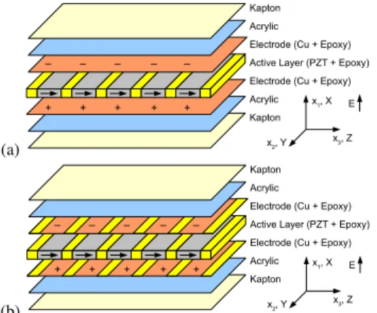
Figure 1. Schematic representations of thickness-shear “d15”
Macro-Fibre Composite with (a) continuous or homogeneous electrodes (Trindade and Benjeddou, 2011) and (b) discontinuous or heterogeneous electrodes (presently proposed).
One of the main difficulties in the study of MFCs, as an alternative to monolithic piezoceramic patches, is that their behaviour may be much more complex since they are made of several different materials (piezoceramic fibres, epoxy matrix, electrode layers and protective layers). Therefore, it is necessary to understand and model their behaviour to be able to quantify or characterize their effective material properties and, thus, their effectiveness as distributed sensors and actuators. Recently, some research effort has been directed towards the identification and characterization of such transducers, in extension (33 or 31) (Deraemaeker et al., 2007, 2009; Deraemaeker and Nasser, 2010; Biscani et al., 2011) and transverse shear (15) (Benjeddou and Al-Ajmi, 2009) modes. It has been shown that the effective properties depend not only on the piezoceramic material used for the fibres and epoxy material used for the matrix and epoxy-to-piezoceramic volume fraction, but also on the geometrical and material properties of the other layers (Kapton, Acrylic, Electrodes). Some analytical methods from the composite materials literature, such as the Asymptotic Homogenization Method (AHM) (Benjeddou and Al-Ajmi, 2009; Otero et al., 2005) and the Uniform Field Method (UFM) (Bent and Hagood, 1997) can be applied to obtain the effective properties of the composite transducer active core from the properties of its components. Alternatively, one may use techniques based on finite element modelling of the composite transducer active core to identify its effective properties (Berger et al., 2005).
A previous study of a shear actuated d15 MFC made of seven layers (Kapton, Acrylic, Electrode, Piezoceramic Fibre and Epoxy Composite, Electrode, Acrylic, Kapton) using a finite element homogenization method to characterize its effective material properties was presented in Trindade and Benjeddou (2011). It has been shown that the packaging reduces significantly the shear stiffness of the piezoceramic material and, thus, leads to significantly smaller effective electromechanical coupling coefficient k15 and piezoelectric stress constante15when compared to the piezoceramic fibre properties. However, it was found that the piezoelectric charge constant d15 is less affected by the softer layers required by the MFC packaging. This work presents, first, an analysis similar to the previous one (Trindade and Benjeddou, 2011) but using another
electrode design and, second, a parametric analysis in which the effect of the variations of fibre volume fraction, Epoxy elastic modulus, electrode thickness and active layer thickness on the effective material properties is evaluated.
Shear Electromechanical Coupling
The shear or d15 response mode requires the poling vector P and main electric fieldE to be perpendicular to each other. From the modelling point of view, this can be achieved as in Fig. 1, by positioning reference axes such that the poling direction, width of fibre or length of actuator, coincides with directionx3 orzand the fibre thickness, and actuator thickness, coincides with directionx1 orx. These reference system and electric configuration provide easy results interpretation as compared to commercial MFCs and standard piezoelectricity notation.
For a linear orthotropic piezoelectric material poled inx3direction and electrodes fully covering top (x+1) and bottom (x−1) surfaces such that a preferential or dominantx1direction is imposed for the electric field and displacement, so thatE2=E3=0, the constitutive equations can be written in the mixede-form type, as
T1 T2 T3 T4 T5 T6 D1 = cE
11 cE12 cE13 0 0 0 0
cE12 cE22 cE23 0 0 0 0 cE13 cE23 cE33 0 0 0 0
0 0 0 cE44 0 0 0
0 0 0 0 cE55 0 −e15
0 0 0 0 0 cE
66 0
0 0 0 0 e15 0 ǫS11 S1 S2 S3 S4 S5 S6 E1 . (1)
whereTpandSq, withp,q=1, . . . ,6, denote the six components of mechanical stress and strain vectors in Voigt notation. D1 and E1 denote the electric displacement and field.cEpq,e15andǫS11denote the elastic stiffness (at constant electric fields), piezoelectric and electric permittivity (at constant mechanical strains) constants.
The electromechanical coupling is then between the electric field and displacement inx1direction,E1andD1, andx1−x3shear stress and strain,T5 andS5. Thus, this is known as ‘15’ operation mode. The electromechanical coupling coefficient can be defined from the value of the coupling or interaction coefficient relative to the principal or diagonal coefficients (Ikeda, 1990) using the standard intensive d-form type of the constitutive equations, such that
k215= d152
sE55ǫT11, (2)
where
d15=e15/cE55,sE55=1/cE55andǫT11=ǫS11+e 2
15/cE55. (3)
It is thus clear that the material properties d15, cE55 and ǫ
T
Table 1. Shear moded15properties of some commercially available piezoceramic materials (Trindade and Benjeddou, 2011). cE
55(GPa) ǫT11/ǫ0 d15(pC/N) e15(C/m2) k215(%) k15
APC-840 26.9 1427 480 13.6 49.0 0.70
APC-850 21.8 1851 590 13.2 46.2 0.68
APC-855 22.4 3012 720 15.0 43.6 0.66
EC-76 21.9 2853 730 16.0 46.2 0.68
EC-64 25.7 1436 506 13.0 51.8 0.72
PIC-255 21.0 1650 550 11.6 43.6 0.66
PZT-5H 23.0 3130 740 17.0 45.6 0.68
PZT-5A 21.1 1730 584 12.3 46.9 0.68
PZT-7A 29.4 930 360 10.6 46.2 0.68
Sonox-P502 30.1 1950 560 16.9 54.8 0.74
Sonox-P504 24.8 1920 530 13.2 43.6 0.66
Sonox-P508 29.8 1700 550 16.4 50.4 0.71
In the case of d15 MFCs which are composed of a number of materials, it is important to identify the effective properties of the ensemble based on its constituents properties. For that, the Representative Volume Element (RVE) technique together with Ansys(R)finite element software is used to evaluate effective material properties of multilayerd15MFCs.
Finite Element Homogenization Technique
In this section, the recently proposed (Trindade and Benjeddou, 2011) finite element homogenization technique is applied to evaluate the effective properties of a d15 MFC including the electrode and protective layers, according to the schematic representation of Fig. 1(b) that shows the new electrode configuration adopted here. It consists in imposing relative mechanical displacement conditions, including symmetry (or periodicity), on the boundaries of the RVE (X1−,X1+,X2−,X2+,X3−,X3+). In addition, electric potential boundary conditions are imposed at the electrodes on surfacesX1e− andX1e+. Relative potentials are also imposed on the other boundaries as symmetry (or periodicity) conditions. In case of the RVE considered for thed15 MFC, shown in Fig. 2, these boundaries areX1−:x1=0, X1+: x1=hP+2(hE+hA+hK), X2−: x2=0, X2+: x2=w, X3−: x3=0, X3+: x3=LP+LE, X1e−: x1=hE+hA+hK, X1e+: x1= hP+hE+hA+hK.
The protective layers, made of Kapton and Acrylic materials, and electrode layer, made of Copper and Epoxy, are considered isotropic. Notice that the isotropy of the electrode layer depends on its design. Electrode designs such as those used ford31 MFC (continuous or woven-type) seem to be more reasonable than those used for thed33 MFC (interdigitated), since the voltage should ideally be constant all over the fibre surfaces. An isotropic continuous electrode (Fig. 1(a)) was considered in a previous work (Trindade and Benjeddou, 2011), but, in this work, a discontinuous electrode (Epoxy/Copper/Epoxy) is considered (Fig. 1(b)).
Average strains and electric fields can therefore be imposed to the RVE using displacements and voltage boundary conditions, such that
uX
+
j
i −u X−
j
i =S¯i j(x X+
j
j −x X−
j
j ),i,j=1,2,3, (4)
and
φX1+−φX −
1 =−E¯1(xX
+
1 1 −x
X1−
1 ). (5)
The resulting average strains, stresses, electric fields and electric displacements in the RVE are defined as
¯ Sq=
1 V
Z
VSqdV, ¯ Tp=
1 V
Z
VTpdV,withp,q=1, . . . ,6, (6) ¯ Ek=
1 V
Z
VEkdV, ¯ Di=
1 V
Z
VDidV,withi,k=1,2,3. (7)
These integrals are approximated in Ansys(R) by a sum over averaged element values multiplied by the respective element volume divided by total volume of the RVE, such that
¯ Sq=
∑Ne=1S(qe)V(e) ∑Ne=1V(e) ,T¯p=
∑Ne=1Tp(e)V(e)
∑Ne=1V(e) ,withp,q=1, . . . ,6, (8)
¯ Ek=
∑Ne=1Ek(e)V(e) ∑Ne=1V(e) ,D¯i=
∑Ne=1D(ie)V(e)
∑Ne=1V(e) ,withi,k=1,2,3. (9)
whereV(e)is the volume of the elemente.S(qe),Tp(e),Ek(e)andD(ie)are the average strains, stresses, electric fields and electric displacements evaluated at elemente. Nis the total number of finite elements used to discretize the RVE.
For the evaluation of the elastic constants related to normal strains and stresses cE
pq, p,q=1,2,3, three local problems are analysed, for which a normal strain Sq (q=1,2,3) is applied by imposing
relative normal displacementsuX
+
q
q −u X−
q
q . In order to obtain ¯Sj=0 if j6=q, the normal displacementsujfor each pair of nodes at opposing surfaces X−j and X+j are set to be equal (symmetrically coupled degrees of freedom). Then, considering the constitutive equations in (1), the effective elastic constants are evaluated using the following expressions
cEpq=T¯p/S¯q, p,q,=1,2,3, (10)
where the average stresses ¯Tpand strains ¯Sqare evaluated using (8). For the evaluation of the elastic constants related to shear strains and stressescEpp, p=4,5,6, other three local problems are analysed for which shear strainsSik(S23=S4/2,S13=S5/2 andS12=S6/2) are applied to approximate a pure shear stress state in the planes x2−x3,x1−x3andx1−x2by imposing relative shear displacements
uX
+
k
i −u X−
k
i at surfacesX + k /X
−
k and u Xi+ k −u
Xi−
k at surfacesX + i /X
−
i . Moreover, the normal displacements at the boundary surfaces parallel to each shear plane of interest are symmetrically coupled to ensure zero strains perpendicular to the shear plane. Therefore, the effective elastic constants are evaluated in terms of the average shear stresses
¯
Tpand strains ¯Spusing
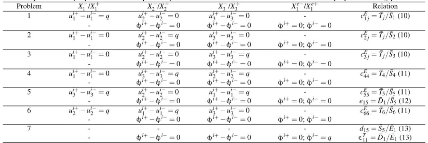
Table 2. Boundary conditions (displacement/electric potential) and relations used to evaluate the effective material properties of ad15piezoelectric MFC.
Problem X1−/X1+ X
−
2 /X2+ X
−
3/X3+ Xe −
1 /X1e+ Relation
1 ui1+−u1i−=q ui2+−u2i−=0 ui3+−ui3−=0 - cE
1j=T¯j/S¯1(10)
- φi+−φi−=0 φi+−φi−=0 φi+=0;φi−=0
2 ui1+−u1i−=0 ui2+−u2i−=q ui3+−ui3−=0 - cE
2j=T¯j/S¯2(10)
- φi+−φi−=0 φi+−φi−=0 φi+=0;φi−=0
3 ui+
1 −ui −
1 =0 ui2+−ui −
2 =0 ui3+−ui −
3 =q - cE3j=T¯j/S¯3(10)
- φi+−φi−=0 φi+−φi−=0 φi+=0;φi−=0 4 ui1+−ui
−
1 =0 ui3+−ui −
3 =q ui2+−ui −
2 =q - cE44=T¯4/S¯4(11)
- φi+−φi−=0 φi+−φi−=0 φi+=0;φi−=0
5 ui+
3 −ui −
3 =q ui2+−ui −
2 =0 ui1+−ui −
1 =q - cE55=T¯5/S¯5(11)
- φi+−φi−=0 φi+−φi−=0 φi+=0;φi−=0 e
15=D¯1/S¯5(12)
6 ui+
2 −ui −
2 =q ui1+−ui −
1 =q ui3+−ui −
3 =0 - cE66=T¯6/S¯6(11)
- φi+−φi−=0 φi+−φi−=0 φi+=0;φi−=0
7 - - - - d15=S¯5/E¯1(13)
- φi+−φi−=0 φi+−φi−=0 φi+=0;φi−=q ǫT
11=D¯1/E¯1(13)
For both the previous cases, equations (10) and (11), to ensure a short circuit electric boundary condition, the voltage degrees of freedom in the electrodes at surfacesX1e−and X1e+ are set to zero. Table 2 indicates symmetric boundary conditions for the electric potential along directionsx2 and x3 for the correspondingX2−/X
+ 2 andX3−/X3+RVE surfaces.
The piezoelectric constante15can be also obtained from the local problem used to evaluatecE55, which is where a pure shear stress state in the planex1−x3 is approximated. From the constitutive equations (1),e15 can be obtained by evaluating the average electric displacementD1such that
e15=D¯1/S¯5. (12)
where the average shear strain ¯S5 and electric displacement ¯D1 are evaluated using the approximation of (8) and (9).
For the evaluation of the piezoelectric and dielectric constants of thed-form,d15 andǫT11, another local problem is set up for which an electric voltageφX1e+=hP (in value) is applied to the electrode at surfaceX1e+ (x1=hP+hE+hA+hK) while the voltage at the opposite electrode (at surfaceX1e−,x1=hE+hA+hK) is set to zero so that a unitary electric field in thex1 direction is generated. To approximate the condition of zero stresses in the RVE, no restriction is made to the displacements in the RVE except for the origin where all displacements are set to zero to prevent rigid body displacements. Then, considering zero shear stressT5in thed-form of the constitutive equations, the piezoelectric and dielectric constants,d15andǫT11, can be evaluated from
d15=S¯5/E¯1andǫT11=D¯1/E¯1. (13)
Table 2 summarizes the local problems used for the characterization of the relevant material properties of the d15 MFC RVE.uij−anduij+are the displacements in direction jandφi−
andφi+are the electric potentials ati-th node of opposite surfaces.q is an arbitrary non-null value.
d15MFC Effective Material Properties Evaluation
Figure 3 shows the finite element mesh used in Ansys(R)for the 7-layeredd15MFC RVE using a FVF of 0.86 for the PZT+Epoxy Active Layer. The 3D 20-Node coupled-field solid finite element SOLID226 was used to mesh all volumes. It has the three displacement translations along the Cartesian coordinate system and the electric
potential as nodal degrees of freedom. 5525 finite elements were used considering 25 divisions inx1direction (13 divisions for the PZT layer and 2 divisions for each electrode and protective layer), 13 divisions in x2direction and 17 divisions inx3direction (11 divisions for the PZT layer and 3 divisions for each Epoxy layer). According to Fig. 2, the dimensions considered for this RVE arehP=1 mm,hK=25.4µm, hA=12.7µm andhE=17.8µm,LP=0.860 mm,LE=0.140 mm and w=1 mm (Raja and Ikeda, 2008). The material properties for the piezoceramic material Sonox P502, taken from Deraemaeker et al. (2009), are: sE11 = sE22 =18.5 pm2/N, sE33 =20.7 pm2/N, sE12=−6.29 pm2/N,sE13=−6.23 pm2/N,sE44=sE55=33.2 pm2/N, sE66=52.3 pm2/N,d31=d32=−185 pC/N,d33=440 pC/N,d15= d24=560 pC/N,ǫT11=ǫT22=1950ǫ0,ǫT33=1850ǫ0. The material properties for the isotropic Epoxy are: Y =2.9 GPa, ν=0.3 and
ǫ=4.25ǫ0. The materials properties for the protective layers, taken from Raja and Ikeda (2008), are: Kapton –Y=2.5 GPa,ν=0.34 andǫ=3.4ǫ0and Acrylic –Y =2.7 GPa,ν=0.35 andǫ=3.4ǫ0. The material properties for the Copper electrode are:Y=117 GPa,
ν=0.35 andǫ=5ǫ0.
P E
hP
h
E
h
A
h
K L
P
0.5L
E 0.5LE
w
+ + +
– – –
h
K
h
A
hE x
3 Z
x
1 X
x
2 Y
Figure 2. Representative volume element (RVE) for ad15MFC.
Table 3. Effective short-circuit material properties ofd15MFC and its active layer for two fibre volume fractions.
FVF = 0.86 FVF = 0.95
MFC active layer 7-layers MFC MFC active layer 7-layers MFC
Y1= 50.09 GPa Y1= 26.43 GPa Y1= 54.81 GPa Y1= 28.72 GPa
Y2= 50.09 GPa Y2= 48.44 GPa Y2= 54.81 GPa Y2= 53.00 GPa
Y3= 20.53 GPa Y3= 19.84 GPa Y3= 37.41 GPa Y3= 35.71 GPa
G23= 6.49 GPa G23= 6.33 GPa G23= 13.09 GPa G23= 12.58 GPa
G13= 6.49 GPa G13= 4.73 GPa G13= 13.09 GPa G13= 7.09 GPa
G12= 16.60 GPa G12= 7.64 GPa G12= 18.22 GPa G12= 8.16 GPa
ν12= 0.43 ν12= 0.23 ν12= 0.43 ν12= 0.23
ν13= 0.20 ν13= 0.15 ν13= 0.21 ν13= 0.13
ν23= 0.20 ν23= 0.22 ν23= 0.21 ν23= 0.22
d15= 486.67 pC/N d15= 485.60 pC/N d15= 532.61 pC/N d15= 532.60 pC/N
e15= 3.13 C/m2 e15= 2.06 C/m2 e15= 6.97 C/m2 e15= 3.40 C/m2 ǫT11= 15.01 nF/m ǫT11= 14.95 nF/m ǫT11= 16.42 nF/m ǫT11= 16.41 nF/m
k2
15= 10.2 % k215= 7.5 % k215= 22.6 % k215= 12.2 %
k15= 0.32 k15= 0.27 k15= 0.48 k15= 0.35
Figure 3. Finite element mesh for the 7-layeredd15MFC RVE with FVF =
0.86.
approximation) (Benjeddou and Al-Ajmi, 2009). Notice however that, in Trindade and Benjeddou (2011), an equivalent homogeneous electrode layer (80% Copper, 20% Epoxy) was considered, whose properties were evaluated using mixture laws, whereas, in the present case, the electrode layer is heterogeneous (Epoxy/Copper/Epoxy) and the Copper portion covers only the piezoceramic fibre, as shown in Figs. 1(b) and 2. The present results are almost exactly the same as in Trindade and Benjeddou (2011).
The results show that the increase in the FVF from 0.86 to 0.95, meaning a 10% increase, leads to an overall increase in the elastic (stiffness) constants. More importantly, the effective piezoelectric properties of major interest to the d15 MFC,d15 or e15, increase substantially by 10% and 123%, respectively, for the active layer. This yields an increase in the effective squared electromechanical coupling coefficientk152 by 123%, from 10% to 23%, for the active layer.
Table 3 also shows that, while the active layer is almost transversally isotropic, the 7-layered composite is definitely orthotropic. In particular, the Young modulus Y1 is significantly diminished due to the relatively soft protective layers. On the other hand, the Young modulusY3 is little decreased mainly due to the electrode that is stiffer than the PZT core and thus promotes a stiffer connection between theX3+ surface and the PZT core. The shear modulusG13 is diminished by 27% (for FVF 0.86) and 46% (for FVF 0.95) due to the protective layers which are softer than the PZT. Notice, however, that the thickness of the protective and electrode layers should also play a major role in this shear modulus, for instance a decrease on the thickness of these layers should increase the shear modulusG13, but will also perform poorly as protective layers. The piezoelectric constantd15 is decreased a little whilee15
is decreased by 30%, from 3.13 to 2.06 C/m2. The dielectric constant
ǫT11is not modified due to the protective and electrode layers, since it is assumed that the electric contact between electrode and PZT occurs at the PZT-electrode interface. This would not be the case if there should be an epoxy layer between Copper electrode and PZT. These effective properties yield an overall smaller electromechanical coupling coefficientk15, such that the efficiency in energy conversion k215decreases by 20%, from 10% to 8%. Notice that this is much less than thek215of the PZT (Sonox P502) alone of 54.8%.
Parametric Analysis
In the previous section, it was noticed that, besides the fibre volume fraction, the packaging design may affect significantly the performance of the MFC transducer. In particular, the softer materials that provide the desired flexibility for the transducer also decrease its performance. Therefore, it is of great interest to analyse the effect of the variation of material and geometrical properties of the MFC on its effective material properties.
In particular, it was observed that the Epoxy material is the main responsible for the decrease of MFC stiffness and, thus, actuation authority represented by the piezoelectric stress constant e15. The MFC effective stiffness may be controlled through either the fibre volume fraction or the Epoxy material stiffness constants, such that an increase of any of them should lead to an increase on the MFC effective stiffness. Thus, in this section, the effect of variations of both fibre volume fraction and Epoxy Young’s modulus is analysed.
On the other hand, the electrode and protective layers also strongly affect the MFC effective material properties, as it can be noticed from the comparison between active layer only and 7-layers MFC of previous section (Table 3). In particular, the materials used for the protective layers are very soft (Epoxy-like stiffness) while the Copper used for the electrode layer is quite stiff. Thus, the effect of variations of electrode layer thickness is also analyzed.
Finally, the active layer thickness is also an interesting parameter since it can be designed for a particular application without significant modification of the packaging design. Therefore, it is also worthwhile to analyze its effect on the transducer performance.
65 70 75 80 85 90 95 10
15 20 25 30 35 40 45 50 55
FVF (%)
Young modulus (GPa)
Y
1
Y2 Y
3
(a)
65 70 75 80 85 90 95
2 4 6 8 10 12 14
FVF (%)
Shear modulus (GPa)
G
23
G13 G
12
(b)
65 70 75 80 85 90 95
0.12 0.14 0.16 0.18 0.2 0.22 0.24
FVF (%)
Poisson ratio
ν23 ν13 ν12
(c)
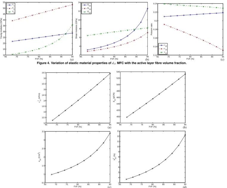
Figure 4. Variation of elastic material properties ofd15MFC with the active layer fibre volume fraction.
65 70 75 80 85 90 95
12 12.5 13 13.5 14 14.5 15 15.5 16 16.5
FVF (%)
∈11
T
(nF/m)
(a)
65 70 75 80 85 90 95
380 400 420 440 460 480 500 520 540
FVF (%)
d15
(pC/N)
(b)
65 70 75 80 85 90 95
0.5 1 1.5 2 2.5 3 3.5
FVF (%)
e15
(C/m
2)
(c)
65 70 75 80 85 90 95
3 4 5 6 7 8 9 10 11 12 13
FVF (%)
k15
2
(%)
(d)
Figure 5. Variation of dielectric, piezoelectric and electromechanical coupling material properties ofd15MFC with the active layer fibre volume fraction.
volume fraction varies from 68% to 95% with 3% increments. The Epoxy elastic modulus is decreased/increased by 10% and 20% from the standard value used in the previous section (YE=2.9 GPa). The Copper electrode thickness is also decreased/increased by 10% and 20% from the value of the previous section (hE =17.8µm). As for the active layer thickness, it varies from 0.25 mm to 1.0 mm with 0.25 mm increments. Notice that, for each parameter set, the seven local problems presented previously (Table 2) are solved and the corresponding effective material properties are evaluated.
In a first analysis, the fibre volume fraction varies in the range from 68% to 95%. Notice that the standard piezoelectric MFC are manufactured using a 86% FVF (Deraemaecker et al., 2007). As expected, all elastic stiffness coefficients increase for higher FVF, since the piezoceramic is much stiffer than the Epoxy (Fig. 4). A more detailed analysis shows, however, that whereas constantsY1, Y2andG12increase linearly with the FVF, the other elastic stiffness constantsY3, G23 and G13 present a non-linear augmentation, as shown in Fig. 4. On the other hand, the Poisson ratiosν13 and
ν12 decrease with increasing FVF andν23increases moderately. As shown in Fig. 5, the piezoelectric and dielectric material properties
increase substantially for higher FVF, since those are only due to the piezoelectric part of the active layer. It can be observed from Fig. 5 thatǫT
11andd15(dielectric and piezoelectric) constants increase linearly with FVF, while piezoelectric constant e15 and squared electromechanical coupling coefficient k215 increase rates augment with FVF, indicating that maximization of FVF is more important for applications using thed15MFC as actuators or energy converters.
−20 −15 −10 −5 0 5 10 15 20 −15
−10 −5 0 5 10 15
Relative Epoxy Young modulus (%)
Relative Young modulus (%)
Y
1
Y2 Y
3
(a)
−20 −15 −10 −5 0 5 10 15 20 −20
−15 −10 −5 0 5 10 15
Relative Epoxy Young modulus (%)
Relative shear modulus (%)
G
23
G13 G
12
(b)
−20 −15 −10 −5 0 5 10 15 20
−4 −3 −2 −1 0 1 2 3 4 5 6
Relative Epoxy Young modulus (%)
Relative Poisson ratio (%)
ν23
ν13
ν12
(c)
Figure 6. Variation of elastic material properties ofd15MFC with Epoxy elastic modulus.
−20 −15 −10 −5 0 5 10 15 20 −1
−0.8 −0.6 −0.4 −0.2 0 0.2 0.4 0.6 0.8 1
Relative Epoxy Young modulus (%)
Relative
∈11
T
(%)
(a)
−20 −15 −10 −5 0 5 10 15 20 −1
−0.8 −0.6 −0.4 −0.2 0 0.2 0.4 0.6 0.8 1
Relative Epoxy Young modulus (%)
Relative d
15
(%)
(b)
−20 −15 −10 −5 0 5 10 15 20 −15
−10 −5 0 5 10
Relative Epoxy Young modulus (%)
Relative e
15
(%)
(c)
−20 −15 −10 −5 0 5 10 15 20 −15
−10 −5 0 5 10
Relative Epoxy Young modulus (%)
Relative k
15
2
(%)
(d)
Figure 7. Variation of dielectric, piezoelectric and electromechanical coupling material properties ofd15MFC with Epoxy elastic modulus.
On the other hand, the dielectric constantǫT
11 of thed15 MFC is not affected by the variation of Epoxy elastic modulus (Fig. 7(a)). The same happens to piezoelectric constantd15(Fig. 7(b)). However, the piezoelectric constante15, which depends on the effective shear stiffness of the composite, increases approximately by 10% when the Epoxy elastic modulus is increased by 20%, as shown in Fig. 7(c). A very similar dependence is observed for the squared electromechanical coupling coefficientk2
15, shown in Fig. 7(d). This indicates that stiffer Epoxy materials should be more interesting for actuators and energy converters applications. Notice, however, that this would also lead to a less flexible (conformable) transducer.
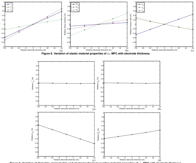
From previous analyses, it seemed that electrode thickness could affect the effective material properties of thed15 MFC, since this layer responds to the major part of the covering layer (electrode and Kapton/Acrylic protective layers) stiffness. Therefore, this property was also varied in the range ±20%. Since a Copper electrode is commonly used, it did not seem appropriate to vary its elastic modulus. For the same reason, the Kapton and Acrylic protective layers material properties were also kept unchanged. Figure 8 shows that an increase of the electrode thickness yields an overall
augmentation of the d15 MFC stiffness constants, although this augmentation is smaller than 1%. Elastic constantsY1,Y2andG12are the most affected by the electrode thickness variation. Poisson ratios are not significantly affected. As for the variation of the previous parameter, dielectric constantǫT11 and piezoelectric constantd15are not affected by the variation of electrode thickness. On the other hand, the piezoelectric constante15decreases a little (0.4%), while the squared electromechanical coupling coefficientk2
15 increases a little (0.2%), for an increase of 20% in the electrode thickness (Fig. 9).
−20 −15 −10 −5 0 5 10 15 20 −1
−0.8 −0.6 −0.4 −0.2 0 0.2 0.4 0.6 0.8 1
Relative electrode thickness (%)
Relative Young modulus (%)
Y1 Y
2
Y3
(a)
−20 −15 −10 −5 0 5 10 15 20 −1
−0.8 −0.6 −0.4 −0.2 0 0.2 0.4 0.6 0.8 1
Relative electrode thickness (%)
Relative shear modulus (%)
G23 G
13
G12
(b)
−20 −15 −10 −5 0 5 10 15 20 −1
−0.8 −0.6 −0.4 −0.2 0 0.2 0.4 0.6 0.8 1
Relative electrode thickness (%)
Relative Poisson ratio (%)
ν23 ν13 ν12
(c)
Figure 8. Variation of elastic material properties ofd15MFC with electrode thickness.
−20 −15 −10 −5 0 5 10 15 20 −1
−0.8 −0.6 −0.4 −0.2 0 0.2 0.4 0.6 0.8 1
Relative electrode thickness (%)
Relative
∈11
T
(%)
(a)
−20 −15 −10 −5 0 5 10 15 20 −1
−0.8 −0.6 −0.4 −0.2 0 0.2 0.4 0.6 0.8 1
Relative electrode thickness (%)
Relative d
15
(%)
(b)
−20 −15 −10 −5 0 5 10 15 20 −1
−0.8 −0.6 −0.4 −0.2 0 0.2 0.4 0.6 0.8 1
Relative electrode thickness (%)
Relative e
15
(%)
(c)
−20 −15 −10 −5 0 5 10 15 20 −1
−0.8 −0.6 −0.4 −0.2 0 0.2 0.4 0.6 0.8 1
Relative electrode thickness (%)
Relative k
15
2
(%)
(d)
Figure 9. Variation of dielectric, piezoelectric and electromechanical coupling material properties ofd15MFC with electrode thickness.
0.2 0.3 0.4 0.5 0.6 0.7 0.8 0.9 1 10
15 20 25 30 35 40 45 50
hP (mm)
Young modulus (GPa)
Y1
Y2 Y3
(a)
0.2 0.3 0.4 0.5 0.6 0.7 0.8 0.9 1 3
3.5 4 4.5 5 5.5 6 6.5 7 7.5 8
hP (mm)
Shear modulus (GPa)
G
23
G
13
G12
(b)
0.2 0.3 0.4 0.5 0.6 0.7 0.8 0.9 1 0.1
0.15 0.2 0.25 0.3 0.35
hP (mm)
Poisson ratio
ν23 ν13 ν12
(c)
Figure 10. Variation of elastic material properties ofd15MFC with active layer thickness.
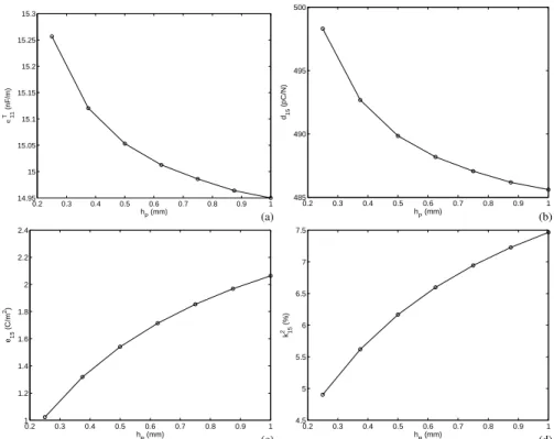
and piezoelectric charge constantd15 are not much affected by the variation of the active layer thickness, increasing around 2% for a decrease on the active layer thickness from 1 mm down to 0.25 mm (Figs. 11(a) and 11(b)). On the other hand, both piezoelectric stress constante15and squared electromechanical coupling coefficientk152 increase substantially for increasing active layer thickness, around
100% fore15and 50% fork215(Figs. 11(c) and 11(d)).
Concluding Remarks
Macro-0.2 0.3 0.4 0.5 0.6 0.7 0.8 0.9 1 14.95
15 15.05 15.1 15.15 15.2 15.25 15.3
hP (mm)
∈11
T
(nF/m)
(a)
0.2 0.3 0.4 0.5 0.6 0.7 0.8 0.9 1 485
490 495 500
hP (mm)
d15
(pC/N)
(b)
0.2 0.3 0.4 0.5 0.6 0.7 0.8 0.9 1 1
1.2 1.4 1.6 1.8 2 2.2 2.4
hP (mm)
e15
(C/m
2)
(c)
0.2 0.3 0.4 0.5 0.6 0.7 0.8 0.9 1 4.5
5 5.5 6 6.5 7 7.5
hP (mm)
k15
2
(%)
(d)
Figure 11. Variation of dielectric, piezoelectric and electromechanical coupling material properties ofd15MFC with active layer thickness.
Fibre Composite (MFC) made of seven layers (Kapton, Acrylic, Electrode, Piezoceramic Fibre and Epoxy Composite, Electrode, Acrylic, Kapton). It confirms that the MFC packaging reduces significantly the shear stiffness of the piezoceramic material and, thus, leading to significantly smaller effective electromechanical coupling coefficientk15 and piezoelectric stress constante15 when compared to the piezoceramic fibre properties. The effect of the variations of fibre volume fraction, Epoxy elastic modulus, electrode thickness and active layer thickness on the MFC effective material properties was evaluated. Results indicated that an effectived15MFC should use relatively thick fibres having relatively high shear modulus and relatively stiff epoxy filler. On the other hand, it was found that the electrode thickness does not affect significantly the MFC performance.
Acknowledgements
The authors acknowledge the support of the MCT/CNPq/FAPEMIG National Institute of Science and Technology on Smart Structures in Engineering, grant no.574001/2008-5.
References
Baillargeon, B.P. and Vel, S.S., 2005, “Exact solution for the vibration and active damping of composite plates with piezoelectric shear actuators,” Journal of Sound and Vibration, Vol. 282, pp. 781-804.
Benjeddou, A. and Al-Ajmi, M., 2009, “Analytical homogenizations of piezoceramicd15shear macro-fibre composites,” Proceedings of the IUTAM
Conference on Multiscale Modelling of Fatigue, Damage and Fracture in Smart Materials, eds. M. Kuna and A. Ricoeur (Freiberg, Germany), Sept 1-4.
Benjeddou, A. and Ranger, J-A., 2006, “Use of shunted shear-mode piezoceramics for structural vibration passive damping,” Computers and Structures, Vol. 84, pp. 1415-1425.
Benjeddou, A., 2007, “Shear-mode piezoceramic advanced materials and structures: A state of the art,”Mechanics of Advanced Materials and Structures, Vol. 14, No. 4, pp. 263-275.
Benjeddou, A., Trindade, M.A. and Ohayon, R., 1997, “A unified beam finite element model for extension and shear piezoelectric actuation mechanisms,”Journal of Intelligent Material Systems and Structures, Vol. 8, No. 12, pp. 1012-1025.
Benjeddou, A., Trindade, M.A. and Ohayon, R., 2000, “Piezoelectric actuation mechanisms for intelligent sandwich structures,”Smart Materials and Structures, Vol. 9, No. 3, pp. 328-335.
Bent, A.A. and Hagood, N.W., 1997, “Piezoelectric fiber composites with interdigitated electrodes,”Journal of Intelligent Material Systems and Structures, Vol. 8, pp. 903-919.
Berger, H., Kari, S., Gabbert, U., Rodriguez-Ramos, R., Guinovart, R., Otero, J.A. and Bravo-Castirello, J., 2005, “An analytical and numerical approach for calculating effective material coefficients of piezoelectric fiber composites,” International Journal of Solids and Structures, Vol. 42, pp. 5692-5714.
Biscani, F., Nasser, H., Belouettar, S. and Carrera, E., 2011, “Equivalent electro-elastic properties of Macro Fiber Composite (MFC) transducers using asymptotic expansion approach,”Composites: Part B, Vol. 42, No. 3, pp. 444-455.
Deraemaeker, A. and Nasser, H., 2010, “Numerical evaluation of the equivalent properties of Macro Fiber Composite (MFC) transducers using periodic homogenization,”International Journal of Solids and Structures, Vol. 47, No. 24, pp. 3272-3285.
Deraemaeker, A., Benelechi, S., Benjeddou, A. and Preumont, A., 2007, “Analytical and numerical computation of homogenized properties of MFCs: Application to a composite boom with MFC actuators and sensors,” III ECCOMAS Thematic Conference on Smart Structures and Materials, eds. W. Ostachowicz et al. (Gdansk, Poland), July 9-11.
Deraemaeker, A., Nasser, H., Benjeddou, A. and Preumont, A., 2009, “Mixing rules for the piezoelectric properties of macro fiber composites,” Journal of Intelligent Material Systems and Structures, Vol. 20, No. 12, pp. 1475-1482.
Ikeda, T., 1990, “Fundamentals of Piezoelectricity,” Oxford University Press.
Otero, J.A., Rodriguez-Ramos, R., Monsivais, G. and Perez-Alvarez, R., 2005, “Dynamical behavior of a layered piezocomposite using the asymptotic homogenization method,”Mechanics of Materials, Vol. 37, pp. 33-44.
Raja, S. and Ikeda, T., 2008, “Concept and electro-elastic modeling of shear actuated fiber composite using micro-mechanics approach,”Journal of Intelligent Material Systems and Structures, Vol. 19, pp. 1173-1183.
vibration control of laminated plates using extension and shear actuated fiber composites,”Smart Materials Research, Vol. 2011, Art. No. 515942.
Raja, S., Prathap, G. and Sinha, P.K., 2002, “Active vibration control of composite sandwich beams with piezoelectric extension-bending and shear actuators,”Smart Materials and Structures, Vol. 11, No. 1, pp. 63-71.
Santos, H.F.L. and Trindade, M.A., 2011, “Structural vibration control using extension and shear active-passive piezoelectric networks including sensitivity to electrical uncertainties,” Journal of the Brazilian Society of Mechanical Sciences and Engineering, Vol. 33, No. 3, pp. 287-301.
Skinner, D.P., Newnham, R.E. and Cross, L.E., 1978, “Flexible composite transducers,”Materials Research Bulletin, Vol. 13, pp. 599-607.
Sun, C.T. and Zhang, X.D., 1995, “Use of thickness-shear mode in adaptive sandwich structures,”Smart Materials and Structures, Vol. 4, No. 3, pp. 202-206.
Trindade, M.A. and Benjeddou, A., 2009, “Effective electromechanical coupling coefficients of piezoelectric adaptive structures: critical evaluation and optimization,”Mechanics of Advanced Materials and Structures, Vol. 16, No. 3, pp. 210-223.
Trindade, M.A. and Benjeddou, A., 2011, “Finite element homogenization technique for the characterization of d15 shear piezoelectric macro-fibre composites,”Smart Materials and Structures, Vol. 20, No. 7, Art. No. 075012.
Trindade, M.A. and Maio, C.E.B., 2008, “Multimodal passive vibration control of sandwich beams with shunted shear piezoelectric materials,”Smart Materials and Structures, Vol. 17, Art. No.055015.
Trindade, M.A., 2011, “Experimental analysis of active-passive vibration control using viscoelastic materials and extension and shear piezoelectric actuators,”Journal of Vibration and Control, Vol. 17, No. 6, pp. 917-929.