Abstract
This paper presents a study on the gap dependent bifurcation behavior of an electro statically-actuated nano-beam. The size-dependent behavior of the beam was taken into account by apply-ing the couple stress theory. Two small and large gap distance regimes have been considered in which the intermolecular vdW and Casimir forces are dominant, respectively. It has been shown that changing the gap size can affect the fundamental frequency of the beam. The bifurcation diagrams for small gap distance re-vealed that by changing the gap size, the number and type of the fixed points can change. However, for large gap regime, where the Casimir force is the dominant intermolecular force, changing the gap size does not affect the quality of the bifurcation behavior.
Keywords
Nano-beam, electrostatic, stability, bifurcation, couple Stress.
Gap Dependent Bifurcation Behavior of a Nano-Beam
Subjected to a Nonlinear Electrostatic Pressure
1 INTRODUCTION
Nowadays, with the rapid development in nano technology, the nano electro-mechanical systems (NEMS) have become one of the hottest research topics. High speed, accuracy and performance and low energy consumption have increased the possibility of substituting the nano technology with micro technology.
NEMS devices such as random access memory, nano tweezers, super sensitive sensors, resona-tors, etc are widely designed, analyzed, fabricated and used (Adu et al., 2001; Collins et al., 2000; Kim and Lieber, 1999; Mobki et al., 2013; Rueckes et al., 2000; Tahami et al., 2009).
There are several actuation mechanisms used in micro and nano electromechanical systems (MEMS & NEMS) such as electrostatic, piezoelectric, thermal, etc (Rezazadeh et al., 2011).
Electrostatically actuated devices form a broad class of MEMS& NEMS devices due to their sim-plicity, as they require few mechanical components and small voltage levels for actuation (Senturia,
Mohammad Fathalilou a Morteza Sadeghi b Ghader Rezazadeh c *
a Mechanical Engineering Department,
University of Tabriz, Iran, [email protected]
b Mechanical Engineering Department,
University of Tabriz, Iran, morteza@ tabrizu.ac.ir
c * Mechanical Engineering Department,
Urmia University, Iran, [email protected]
Latin American Journal of Solids and Structures 11 (2014) 2426-2443
2011). In such circumstances, a conductive flexible beam or plate is suspended over a ground plate and a potential difference is applied between them. As the microstructure is balanced between elec-trostatic attractive force and mechanical (elastic) restoring force, both elecelec-trostatic and elastic re-storing forces are increased by the upsurge of the electrostatic voltage. When the voltage reaches the critical value, pull-in instability will occur. Pull-in is the point at which the elastic restoring force can no longer balance the electrostatic force. Further increasing the voltage, gives rise to the dramatic displacement jump in the structure, causing structure collapse and fail. Pull-in instability is a snap-through like behavior and a saddle-node bifurcation type of instability (Zhang et al., 2006).
In NEMS devices, by decreasing the geometric dimension, intermolecular surface forces such as van der Waals force and Casimir force can affect the structure behavior. vdW force and Casimir force can both be connected with the existence of zero-point vacuum oscillations of the electromag-netic field (Batra et al., 2007; Bordag et al., 2001; Klimchitskaya, 2000; Lifshitz, 1956; Moeenfard et al., 2012).
The microscopic approach to the modeling of both vdW and Casimir forces can be formulated in a unified way using Quantum Field Theory (Bordag et al., 2001; Klimchitskaya, 2000; Lamoreaux, 2005; Lifshitz, 1956). Batra et al. (2008) have reported that the Casimir force is generally effective at larger separation distances between the bodies than the vdW force. Whereas the Casimir force between semi-infinite parallel plates is inversely proportional to the fourth power of the gap, vdW force is inversely proportional to the third power of the gap. The dependence of these forces on the dielectric properties of the plates and the filling medium is studied in detail by Bordag et al. (2001). It is important to note that vdW and Casimir forces cannot in general be considered to simultane-ously act in MEMS, since they describe the same physical phenomenon at two different length scales (Batra et al., 2008).
Although these forces have been explored for decades but they are rarely considered in analyzing the mechanical behavior and calculating the Pull-in voltage of the NEMS systems (Tahami et al., 2009).
Latin American Journal of Solids and Structures 11 (2014) 2426-2443
takes place. Palasantzas et al. (2008) have shown that the transition from vdW to Casimir regime is rather weak. They have obtained for two parallel gold surfacesabout 18 nm gap distance for the crossover from vdW to Casimir regime, whereas Lambrecht and Reynaud (2000) have predicted theoretically about 13 nm for the transition.
On the other hand, many researches showed that in micro and nano scales the materials have strong size dependence in deformation behavior (Papargyri-Beskou et al., 2003; Lazopoulos and Lazopoulos, 2010; Asghari et al., 2010; Park and Gao, 2006; Fu and Zhang, 2011; Kong et al., 2008, 2009; Fathalilou et al., 2011). Size-dependent behavior is an inherent property of materials, which appears for a beam when the characteristic size such as thickness or diameter is close to the internal length-scale parameter of materials (Fathalilou et al., 2011). However, in some materials, remarka-ble discrepancies are observed between the experimental results and those obtained using classical elasticity theory. These discrepancies are mainly due to the dominance of atomic structures of the material neglected in classical elasticity (singh, 2008). So, the static or dynamic behavior of these structures cannot be correctly described by the classical linear elasticity and higher order mechani-cal theories must be applied (Papargyri-Beskou and Beskos, 2008).
Voigt was the first who tried to correct these shortcomings of the classical elasticity by taking into account of the assumption that interaction between the two parts through an area element inside the body is transmitted not only by a force vector but also by a moment vector giving rise to a 'couple stress theory' (Voigt, 1887). The complete theory of asymmetric elasticity was developed by Cosserat and Cosserat (1909), which was non-linear from the beginning. They assumed that each material point of a three dimensional continuum is associated with a 'rigid triad' and during the process of deformation; it can rotate independently, in addition to the displacement (singh, 2008). After a gap of about fifty years, Cosserats theory drew attention of researchers and several Cosse-rat-type theories were developed independently, e.g., Gunther (1958), Grioli (1960), Ra- jagopal (1960), Palmov (1964), Aero and Kuvshinskii(1960), Mindlin and Tiersten (1962), Toupin (1962), Eringen (1962), Koiter (1964), Nowacki (1974) among several others. Later, the general Cosserat continuum theory acquired the name of 'micropolar continuum theory' following Eringen (1966), in which the micro-rotation vector is taken independent of the displacement vector. Eringen and Su-hubi (1964) and SuSu-hubi and Eringen (1964) developed a non-linear theory for 'micro-elasticity', in which intrinsic motions of the microelements were taken into account. The general theory of Mindlin (1964) includes three equivalent forms which are defined on the basis of three different expressions for the strain energy density (Papargyri-Beskou and Beskos, 2008). The first expression involves gradients of displacements, the second one the gradients of strain, and the third one the gradients of rotation. The couple stress theory is based on the third expression of the strain energy density while second form gives rise to the gradient elastic theory.
Recently, some researchers have applied the non-classic theories of elasticity to study the me-chanical behavior of electrostatically actuated micro and nano beams Asghari et al., 2010; Fu and Zhang, 2011; Kong et al., 2008, 2009; Fathalilou et al., 2011).
Latin American Journal of Solids and Structures 11 (2014) 2426-2443
and large gap distances, respectively. It is obtained that the fundamental frequency of the nano-beam can be gap dependent. Also, it is understood from bifurcation analysis that changing the ini-tial gap size can changes the number and type of bifurcation points.
2 MATHEMATICAL MODELING AND NUMERICAL SOLUTION
2.1 Distributed model
Figure 1 shows an electrostatically actuated fixed-fixed Euler-Bernoulli nano-beam. The device con-sists of a beam, suspended over a dielectric film deposited on top of the center conductor and fixed both ends to the ground conductor. When a direct voltage (DC voltage) is applied between the upper and lower electrodes, the upper deformable beam is pulled down due to the electrical force.
Figure 1:An electrostatically actuated fixed-fixed nano-beam.
The rectangular cross-section beam is considered with length L, thickness h, and width b, and ini-tial gap ofg0. The nano-beam is assumed to be isotropic with Young modulus E and density
.Together with the attractive electrostatic force, the vdW and Casimir forces pull the nano-beam down towards the substrate. Minimum length of the nano-beam in which vdW and Casimir forces lead the nano-beam to collapse on the substrate (in lack of the electrostatic force) is known as the detachment length (Tahami et al., 2009).
In the linear couple stress theory the strain energy of the deformed body is assumed to depend upon the strain
and the rotation gradient
, so that the associated stress quantities are the sym-metric Cauchy stress tensor
and the deviatoric couple stress tensor
(Mindlin, 1964).It follows that the strain energyE
s in a deformed isotropic linear elastic material occupying regionV will be:
1
( )
2
s ij ij ij ij V
E =
ò
s e +m k dv(1)
Also, the kinetic energy of the body motion is as following: 1
2
k i i V
E =
ò
ru u dv (2)
The constitutive equations of the theory are given considering the following expression for the strain energy density
e
s (Mindlin, 1964):1
2 2
2
s ii jj ij ij ij ij ij ji
Latin American Journal of Solids and Structures 11 (2014) 2426-2443
where
and
are two Lame’s constants of the classical elasticity whereas
and
are two non-classic Lame-type material constants which introduce the couple stress effects.Eq. (3) leads to the following constitutive equations:
s 2
ij ij kk ij ij
e
s ld e me
e ¶ = = + ¶ 4 4 s
ij ij ji ij
e
m hk h k
k
¶ ¢
= = +
(4)
It is time now to introduce the governing equation for the beam of Figure 1 considering couple stress effects. Primarily, it is mentioned that i, j and k indices vary from 1 to 3; representing the var-iables in x, y and z directions in Cartesian coordinates, respectively. Using the coordinate system (x,z) shown in Figure 1, where x-axis coincides with the centroidal axis of the un-deformed beam and z-axis is the symmetry axis, the displacement components of an Euler-Bernoulli beam, neglect-ing the mid-point displacement in x direction can be represented by (Park and Gao, 2006):
, 0, ( , )
w
u z v w w x t
x
= - = =
¶ (5)
where u, v and w are, respectively, the (x, y) and z components of the displacement vector.
Considering Eq. (5), the components of the symmetric strain tensor for the plane stress and plane strain conditions are as following, respectively:
2 2 xx u w z x x
e = ¶ = - 
¶ 
Plane stress: 2 2
2, 2, 0
yy zz xy yz zx
w w
z z
x x
e =n ¶ e =n ¶ e =e =e =
¶ 
Plane Strain: 0, 22, 0
(1 )
yy zz xy yz zx
w z
x
n
e e e e e
n 
= = = = =
- 
(6)
The components of the rotation vector can be written as:
, 0
y x z
w x
q = -¶ q = q =
¶ (7)
Now, the components of the asymmetric rotation-gradient tensor are as following:
2
2
xy
w
x
k = -¶ 
0
xx yy zz yx xz zx zy yz
k = k =k = k = k = k = k = k =
(8)
Substituting Eqs. (6) and (8), into Eq. (4) the following relation is obtained for the strain energy density of the plane strain condition:
2
2 2 2 2
2
1 1 2
1 2
2 1 1
s
u w
e
x x
n n
l m h
n n
æ æ ö æ æ ö öö÷÷æ ö æ ö ç ç - ÷ ç ç ÷ ÷÷ç¶ ÷ ç¶ ÷
ç ç ÷÷ ÷
Latin American Journal of Solids and Structures 11 (2014) 2426-2443
where
is the shear modulus and(
)
2(
)
2 21 2 1 2 1 1 E 1 E
l - n -n + mçèçæç + n -n ö÷ø÷÷= -n = , is the elasticity
modulus of the material in plane strain condition. As seen in this relation, the strain energy in beam model does not depend on
, and one non-classical material constant only appears in this model which is defined as:2
l
h = m (10)
where l is the material length scale parameter (Anthoine, 2000; Mindlin, 1964).
Considering mentioned relations and applying the Hamilton principle the governing equation with couple stress is obtained as following:
4 2
2
4 2
4 w w ext
EI b l bh
t q h
x
m ¶ r 
é + ù + =
ê ú
ë û ¶ ¶ (11)
with the following boundary conditions:
0 w w x ¶ = =
¶ at x =0, L
(12)
Clearly, when the couple stress effect is suppressed by letting l=0, the present model defined by Eq. (11) will reduce to the classical Euler-Bernoulli beam model. In Eq. (11),
q
ext is considered as the sum of the electrostatic, vdW and Casimir forces as following (Tahami et al., 2009):ext e v C
q =q +q +q (13)
where
2 2
0
2 3 4
0 0 0
, ,
ˆ ˆ
2( ) 6 ( ) 240( )
e v C
bV Ab b hc
q q q
g w g w g w
e p
p
= = =
- - - (14)
In these equations, 12 2 1 2
0 8.854 10 C N m
e = ´ - - - is the permittivity of vacuum within the gap, V is the applied direct voltage, h =1.055´10-34Js is the Planck's constant, c= 2.998´108ms-1is the light speed, and 2 2
1
A=p rC is Hamaker constant which lies in the range of (0.4- ´4) 10-19J
(Tahami et al., 2009). For convenience, Eq. (11) may be cast into a non-dimensional form; in par-ticular, both the transverse displacement, wand the spatial coordinate, x are normalized by charac-teristic lengths of the system and the gap size, and beam length, respectively, according to:
0
ˆ /
w =w g andxˆ=x /L. Time t in non-dimensional form is given as: tˆ=t/t*where
* ( 4 / )1/2
t = rbhL EI is the classic characteristic fundamental period of the system. Substituting
these parameters into Eq. (11), the following non-dimensional equation is obtained:
2
4 2 3 4
4 2
2
ˆ (1 ) (1 ) (1
ˆ ˆ
(1 )
ˆ ˆ ˆ
ˆ )
w w
x w w
V
w t
a ¶ ¶ b + g + h
- -
-+ + =
Latin American Journal of Solids and Structures 11 (2014) 2426-2443
The parametersα, , andηappeared in Eq. (15) are:
2
2
48 l Eh
m
a = , 4
3 3 0
6 L Eh g
b = e , 4
3 3 0
6AbL Eh g
g = , 4
3 5 0 20 hcL Eh g p
h = (16)
The static equation can be derived by dropping the time dependent terms from the dynamic equa-tion of moequa-tion:
4
4
2
2 3 4
(1 ) (1 ) (
ˆ (1 )
ˆ ˆ )
ˆ 1 ˆ
w
x w
V
w w
b g h
a + +
- -
-
+ =
¶ (17)
Due to the nonlinearity of the derived static equation, the solution is complicated and time consum-ing. Direct application of either Galerkin or finite difference methods will produce a set of nonlinear algebraic equation. To avoid this problem, we adopted the step-by-step linearization method (SSLM) (Rezazadeh et al., 2011), followed by Galerkin method to solve the obtained linear set of algebraic equations. For using SSLM, it is assumed that wˆk is the displacement of the beam due to
the applied voltage Vk. The vdW and Casimir forces only depend on the non-dimensional gap size
and their value cannot be controlled manually. In order to solve this problem, it is assumed that these forces being applied gradually in a virtual manner. For this purpose, a virtual variablelis introduced which varies from zero to one. Multiplying this variable by vdW and Casimir forces, the assumption of the step by step change of the load can be satisfied (Zarei and Rezazadeh, 2008). Now, wˆkis defined as the non-dimensional displacement of the nanostructure when subjected to Vk
under the virtual nano scaled vdW and Casimir forces. Then by increasing the voltage and conse-quent virtual force variablel, the deflection of the (k+1)th step can be obtained as:
1
k k
V + =V +dV & lk+1 =lk +dl & wˆk+1 =wˆk +dwˆ =wˆk +y (18)
wheredV and dl are the voltage and virtual force variable, changing between two successive steps,
respectively. By considering a small value of dV and dl the y will be small enough so that we can
use the first term of the Taylor expansion in each step instead of exact main excitation function. The equation for kthstep is:
2 4
4 2 3 4
ˆ ( )
(1 ) ( )
ˆ ˆ ˆ
ˆ (1 ) (1 ) (1 )
k
k
k k k
k
V d w
dx w w w
b g h
a l
+ = + +
- - - (19)
and for (k+1)thstep:
1 2 4
1
4 1 2 1 3 1 4
1
ˆ ( )
(1 ) ( )
ˆ ˆ ˆ
ˆ (1 ) (1 ) (1 )
k
k
k k k
k
V d w
dx w w w
b g h
a + l +
+ + +
+
+ = + +
- - - (20)
Latin American Journal of Solids and Structures 11 (2014) 2426-2443 2
4
4 3 4 5
2 3 4
2 ( ) 3 4
(1 ) ( )
ˆ ˆ ˆ
ˆ (1 ) (1 ) (1 )
2
( )
ˆ ˆ ˆ
(1 ) (1 ) (1 )
k
k
k k k
k
k k k
V d
d x w w w
V V
w w w
b
y g h
a l y
b g h
d dl
æ ö÷
ç ÷
ç
+ -ç + + ÷ =
÷÷
çè - - - ø
+ +
- -
-(21)
The obtained linear differential equation is solved by Galerkin method. ( )yxˆ having basis in function
space, may be expressed as:
( )
( )
1
ˆ j j ˆ
j
x a x
y f
¥
=
=
å
(22)The fj( )xˆ is jthshape function which satisfies the given boundary conditions. In this paper, the shape functions are selected as the linear undamped natural mode shapes of the beam.
The unknown ( )yxˆ is approximated by truncating the summation series to a finite number, n:
( )
( )
1
ˆ ˆ
n n j j
j
x a x
y f
=
=
å
(23)Substituting Eq. (23) into (21), multiplying by fj( )xˆ as a weight function in Galerkin method and integrating the outcome from xˆ= 0 to 1 a set of linear algebraic equation is generated as:
1
, 1, , n
ij j i j
K a F i n
=
= = ¼
å
(24) where( )
(
)
(
)
(
)
2 1 4 5 3 0(1 ) 2 3 4
ˆ ˆ ˆ
1 1 1
ˆ
iv
ij j j
k k k
i j
k k k
s s s
j
V
d
w w w
K f a f b f g l f h l f x
é ù
ê ú
ê ú
= ê + - - ú
ê - - - ú
ë û
-ò
(
)
2(
)
3(
)
41
0
2
ˆ ˆ ˆ
1 1 1
ˆ
k i
k k k
s s s
i
V
dV d
w w w
F f b g dl h dl x
é ù
ê ú
ê ú
= ê + + ú
ê - - - ú
ë û
ò
(25)
Dynamic loading response may be obtained using Galerkin-based reduced order model (Nayfeh and Mook, 1979). Due to the non-linearity of the external forces, direct application of the reduced order model to the dynamic equation (Eq. (15)) leads to generation of n nonlinear-coupled ordinary differ-ential equation. To solve this difficulty, the forcing terms in Eq. (15) is considered as a constant in each integration time step, which takes the value of the previous step. Selecting time steps small enough, leads to satisfactory results. To achieve a reduced order model, w x tˆ ˆ, ˆ
( )
may be approximat-ed as:( )
( )
1
ˆ ˆ
ˆ ˆ, ( ) ˆ
n j j j
w x t T t f x =
=
å
(26)
By substituting Eq. (26) into Eq. (15) and multiplying by fi( )xˆ as a weight function in Galerkin
Latin American Journal of Solids and Structures 11 (2014) 2426-2443
1 1
( )ˆ ( )ˆ
n n
ij ij i
j j
j ij
T t K t F
M T
= =
+ =
å
å
(27)where M and K are mass and mechanical stiffness matrices, respectively. Also F introduces the forcing vector. The mentioned matrices and vector are given by:
1
0
ˆ ij i j
M =
ò
f fdx1
0
[(1 ) ] ˆ ij
iv i j
K =
ò
f +a f dx,
1
0
ˆ i i ext
F =
ò
fq dx
(28)
Now, Eq. (27) can be integrated over time by various integration methods such as Runge-Kutta method whereqextin each time step of integration takes the value of previous step.
2.2 Lumped model
A lumped model can be helpful to gain a rough quantitative estimation for the response of a wide range of electrostatically-actuated micro and nano-structures (Rezazadeh et al., 2011). The lumped model shown in Figure 2 is utilized to represent a NEMS device employing electrostatic actuation. The device has a movable nano-beam of mass m, which forms one side of a variable capacitor. A spring with coefficient k is used to model the effective stiffness of the nano-beam, which is due to the elastic restoring force (Rezazadeh et al., 2011).
Figure 2:A lumped model of the nano-beam.
Considering the couple stress theory, the equivalent mass (m) and stiffness (k) for a lumped model of the fixed-fixed nano-beam are considered as:m =0.41 bhLr
&
k =384(EI +4Gbhl2) /L3 (Rezaza-deh et al., 2011).
Latin American Journal of Solids and Structures 11 (2014) 2426-2443 2
2 2
0
2 2 3 4
0 0 0
2( ) 6 ( ) 240( )
bLV
d z AbL b hcL
m kz
dt g z g z g z
e p
p
+ = + +
- - - (29)
where z introduces displacement of the mass defined to be positive downward.
For adjusting the lumped model with distributed one, a model corrective coefficient a=1.11can be multiplied to k to obtain a modified stiffness (Rezazadeh et al., 2011).
For convenience in analysis, Eq. (29) can take a nondimensional form with nondimensional varia-bles as following:
0
ˆ z
z g
=
and
tˆ t
t*
= (30)
where t*is the characteristic time and equal to m/k .
Using the nondimensional parameters, the governing equation is rewritten as following:
2 2
1 2 3
2 2 3 4
ˆ ˆ
ˆ ˆ ˆ
(1 ) (1 ) (1 )
D V D D
d z z
dt + = -z + -z + -z (31)
whereD1 , D2 and D3are nondimensional parameters and defined as following:
2 0
1 3 2 4 3 5
0 0 0
, ,
2 6 240
bL AbL bLhc
D D D
kg kg kg
e p
p
= = = (32)
The static equation of deflection can be obtained by dropping time from Eq. (31) as following:
2
1 2 3
2 3 4
ˆ
ˆ ˆ ˆ
(1 ) (1 ) (1 )
D V D D
z
z z z
= + +
- - - (33)
Using this equation, one can obtain the fixed points of the system by changing voltage as a parame-ter control. For analyzing the stability of the fixed points, a phase diagram for each voltage can be plotted. To this end, Eq. (31) can be solved by various methods such as Runge-Kutta method.
3 RESULTS AND DISCUSSION
In order to validate our results, the obtained pull-in voltages are compared to those obtained by Tahami et al. (2009) for a fixed-fixed silicon nano-beam with g0 =10 nm and 6 h = nm. They have considered classic elasticity theory to obtain their results. They have obtained 6.78 V for pull-in voltage of this beam by considering the vdW force when the length is taken asL =180 nm.Also,
forL =230 nm, they obtained 4.11 V. Our results are 6.77 V and 4.11 V for these two cases, re-spectively. As seen, there is a good agreement among the results.
For analyzing the bifurcation behavior, a capacitive gold nano-beam is considered with geome-tries and material properties as shown in Table 1. The length scale parameter is taken as 0.5 h. It
Latin American Journal of Solids and Structures 11 (2014) 2426-2443
Design Variable Value
L 600 nm
b 50 nm
h 10 nm
E 111 GPa
ρ 19320 kg/m3
ν 0.44
Table 1: Geometrical and material properties of the gold nano-beam.
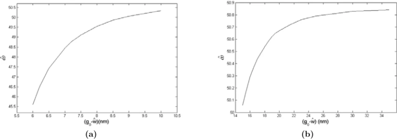
As mentioned the vdW and Casimir forces pull down the movable beam. So it is expected that con-sidering these forces changes the fundamental frequency of the beam. Figures 3a and b show the gap dependent fundamental frequency (
ˆ
) of the nano-beam without an electrostatic actuation for small and large gap regimes, respectively. As illustrated, for small gaps the rate of increasing the fundamental frequency with increasing the gap is higher than large distances. Also, for the beam with mentioned specifications, after the gap of 30 nm the frequency converges to a constant value.(a) (b)
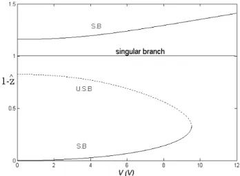
Figure 4 shows the bifurcation behavior of the nano-beam in state-control space for g0 =6 nm. It can be seen that for applied voltages smaller than pull-in voltage, there are two fixed points. For voltages between 0.7-1.7 V, no fixed points are observed in this space. For voltages higher than
1.7 V two fixed points are observed again, but for z >1, which is physically impossible.
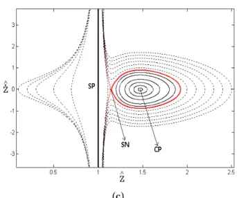
Figure 5 illustrates the stability of these fixed points. Figures 5a, b and c include phase diagram of the nano-beam for V =0 , 1 V V = V and 2V = V , respectively. In Figure 5a, it can be found that the first equilibrium position is a stable centre point (CP) and the second is an unstable sad-dle-node (SN). As shown in this Figure, there are two basins of attraction of stable centers and a basin of repulsion of unstable saddle node. The first basin of attraction of the first stable center is bounded by a closed orbit and the second basin of attraction of the second stable is an unbounded region. Depending on the location of the initial condition the system can be stable or unstable.
Latin American Journal of Solids and Structures 11 (2014) 2426-2443
ure 5b, confirms that there is not any types of fixed points at above or under the substrate for 1
V = V . As shown in Figure 5c, forV =2V , there are mathematically stable center and saddle
node under the substrate which are physically impossible.
In addition as shown in Figure 4, in the state-control space, the stable and unstable branches of the fixed points with changing applied voltage meet together at a saddle-node bifurcation point. The voltage corresponding to the saddle-node bifurcation pointon the upper side of the substrate is a critical value, which is known as static pull-in voltage in the MEMS and NEMS Literature. In other words, when the applied voltage equal to the static pull-in voltage there is no any basin of stable attractors on the upper side of the substrate and the micro-beam is unstable for every initial condition. Now, with attention to Figure 5, the stable and unstable branches (S.B and U.S.B) of the bifurcation diagram can be determined. Also, it must be mentioned that for a given voltage there is a singular point (SP) at
z=1.
It must be mentioned that as seen in Figure 4, forV=0V,
the stable fixed point is not displaced in not displaced position (z=0). This is due to the existence of the in-termolecular force, which has displaced the mass initially.Figure 4:Variation of the center gap of the nano-beam with applied voltage for g0 =6 nm
Latin American Journal of Solids and Structures 11 (2014) 2426-2443 (c)
Figure 5:Phase diagram of the nano-beam for g0 =6 nm and various initial
conditions, a)V=0V, b) V=1V, c) V=2V.
In Figure 6 the state-control space is plotted when g0 =8 nm. As shown, besides increasing the pull-in voltage, the voltage ranges in which no fixed points are observed have became smaller.
Figure 6:Variation of the center gap of the nano-beam with applied voltage for g0 =8 nm.
It can be understood that by increasing the gap distance the voltage range with no fixed points tends to zero and even for some ranges four fixed points can be seen in state-control space. As an instant this problem can be seen in Figure 7, where the gap size is g0 =10 nm.
Figures 8a, b and c illustrate the stability of these fixed points for V =0 , 2 V V = V and 2.5V = V
,
respectively.
As shown, forV =0V the stable center point and saddle node appear only on upperside of the substrate, whereas for V =2.5V the center point and saddle node exist under the
Latin American Journal of Solids and Structures 11 (2014) 2426-2443
both side of the substrate include a center point and a saddle node which is in agreement with Fig-ure 7.
Figure 7:Variation of the center gap of the nano-beam with applied voltage for g0 =10 nm.
(a) (b)
(c)
Latin American Journal of Solids and Structures 11 (2014) 2426-2443 a) V=0V, b) V=2V, c) V=2.5V.
For large gap distance regime, the Casimir force is only considered in addition to the electrostatic force. Figures 9 and 10 illustrate the bifurcation diagram of the nano-beam with g0 =15 nmand
0 25
g = nm, respectively. It is understood that for all gaps above 15 nm there are three fixed
points before pull-in voltage. One of them is under the substrate which is physically impossible, but other two points are above the substrate. On the other hand, for voltages higher than pull-in volt-age there is only one fixed point which is under the substrate. To investigate the stability of these fixed points, the phase diagram forg0 =15 nmis plotted in Figure 11. As shown, for V=0V, the first fixed point is a stable center point, the second is a saddle node which are on upper side of the substrate and the third one is a mathematically stable center which is physically impossible.
Figure 9:Variation of the center gap of the nano-beam with applied voltage for g0 =15 nm.
Latin American Journal of Solids and Structures 11 (2014) 2426-2443 Figure 11:Phase diagram of the nano-beam for various initial conditions forg0 =15 nmand V=0V.
4 CONCLUSIONS
In presented work, gap dependent bifurcation behavior of an electrostatically-actuated gold nano-beam was studied. Both distributed and lumped models were introduced to explain the nano-nano-beam deformation considering the couple stress theory. The results showed that fundamental frequency of the nano-beam can be gap dependent and the rate of the change in the frequency was higher for small gap regimes than large distances. In the bifurcation analysis, the following results were ob-tained:
1. In the both small and large gap regimes, for the voltages lower than the pull-in voltage, two stable and unstable fixed points appear on upper side of the beam.
2. For the small gap regime, a voltage range can be found in which no fixed point appears, whereas for large gaps there is not such a range.
3. For the large gap distances, for all voltages, there is one mathematically stable fixed point under substrate plate which is physically impossible, whereas for the small gaps we have two voltage ranges; in first range, there is not any fixed pint under the substrate and in second one two mathe-matically stable and unstable branches meet together in a saddle node. In this case the distance between two saddle nodes on the upper and lower sides of the substrate plate varies with changing gap size.
References
Adu, C. K. W., Sumanasekera, G.U., Pradhan, B.K., Romero, H.E., Eklund, P.C. (2001). Carbon nanotubes: a thermoelectric nano-nose. Chemistry Physics Letter 337: 3135.
Aero, E.L., Kuvshinskii, E.V. (1960). Fundamental equations of the theory of elastic media with rotationally inter-acting particles, Fizika Tverdogo Tela 2: 1399-1409.
Anthoine, A. (2000). Effect of couple-stresses on the elastic bending of beams. International Journal of Solids and Structures 37: 1033–1018.
Latin American Journal of Solids and Structures 11 (2014) 2426-2443
Batra, R.C., Porfiri, M., Spinello, D. (2007). Effects of Casimir force on pull-in Instability in micromembranes. A Letters Journal Exploring The Frontiers of Physics 77: 16.
Batra, R.C., Porfiri, M., Spinello, D. (2008). Reduced-order models for microelectromechanical rectangular and circu-lar plates incorporating the Casimir force. International Journal of Solids and Structures 45: 3558–3583.
Bordag, M., Mohideen, U., Mostepanenko, V.M. (2001). New developments in the Casimir effect. Phys. Rep. 353: 1– 205.
Boström, M., Sernelius, B., Brevik, I., Ninham, B.W. (2012). Retardation turns the van der Waals attraction into a Casimir repulsion as close as 3 nm. Physics Review A. Atomic, Molecular, and Optical Physics 85: 1010701.
Collins, P.G., Bradley, K.B., Ishigami, M., Zettl, A. (2000). Extreme oxygen sensitivity of electronic properties of carbon nanotubes. Science 287: 18011804.
Cosserat, E., Cosserat, F. (1909). Theorie des Corps Deformables, Hermann et Fils, Paris.
Dequesnes M., Rotkin, S.V., Aluru, N.R. (2002). Calculation of pull-in voltages for carbon nano-tube-based nanoelec-tromechanical switches. Nanotechnology 13:120131.
Eringen, A.C. (1962). Nonlinear Theory of Continuous Media, Mc Graw-Hill, New York.
Eringen, A.C., Suhubi, E.S. (1964). Nonlinear theory of simple microelastic solids I. Internatinal Journal of Engi-neering Science 2: 189–203.
Eringen, A.C. (1966). Linear theory of micropolar elasticity. Journal of Mathematics and Mechanics 15: 909–924. Fathalilou, M., Sadeghi, M., Rezazadeh, G., Jalilpour, M., Naghiloo, A., Ahouighazvin, S. (2011). Study on the Pull-in Instability of Gold Micro-Switches UsPull-ing Variable Length Scale Parameter. International Journal of solid Mechan-ics 3: 114-123.
Fu, Y., Zhang, J. (2011). Size-dependent pull-in phenomena in electrically actuated nanobeams incorporating surface energies. Applied Mathematical Modelling 35: 941–951.
Grioli, G. (1960). Elasticita asimmetrica. Annali di Matematica Pura ed Applicata, Series IV 50: 389–417.
Gunther, W., (1958). Zurstatik und kinematik des cosseratschen kontinuums. Abhand-lungen der Braunschweigischen Wissenschaftlichen Gesellschaft, 10: 195–213.
Kim, P., Lieber, C. M. (1999). Nanotube Nanotweezers. Science 286: 21482150.
Klimchitskaya, G.L., Mohideen, U., Mostepanenko, V.M. (2000). Casimir and van der Waals forces between two plates or a sphere (lens) above a plate made of real metals. Phys. Rev. A 61: 062107.
Kong, Sh., Zhou, Sh., Nie, Zh., Wang, K. (2008). The size-dependent natural frequency of Bernoulli–Euler micro-beams. International Journal of Engineering Science 46: 427-437.
Kong, Sh., Zhou, Sh., Nie, Zh., Wang, K. (2009). Static and dynamic analysis of micro beams based on strain gradi-ent elasticity theory. International Journal of Engineering Science 47: 487-498.
Koiter, W.T. (1964). Couple-stresses in the linear theory of elasticity. Proceedings Konin Klije Nederlandse Akademie van Wetenshappen 67: 17–29.
Lambrecht, A., Reynaud, S. (2000). Casimir force between metallic mirrors. European Physics Journal 8: 309–318. Lamoreaux, S.K. (2005). The Casimir force: background, experiments, and applications. Rep. Prog. Phys. 68: 201– 236.
Lazopoulos, K.A., Lazopoulos, A.K. (2010). Bending and buckling of thin strain gradient elastic beams. European Journal of Mechanics A/Solids 29: 837-843.
Lifshitz, E.M. (1956). The theory of molecular attractive forces between solids. Soviet Physics JETP 2: 73–83. Lin, W.H., Zhao, Y.P. (2005). Nonlinear behavior for nanoscale electrostatic actuators with Casimir force. Chaos, Solutions and Fractals 23: 17771785.
Mindlin, R.D., Tiersten, H.F. (1962). Effects of couple-stresses in linear elasticity. Archive for Rational Mechanics and Analysis 11: 415–448.
Mindlin, R.D. (1964). Micro-structure in linear elasticity. Archive for Rational Mechanics and Analysis 16: 51–78. Mobki, H., Sadeghi, M., Rezazadeh, G., Fathalilou, M. (2013). Nonlinear behavior of a nano-scale beam considering length scale parameter. Applied Mathematical Modeling. Available online.
Latin American Journal of Solids and Structures 11 (2014) 2426-2443 Nayfeh, H., Mook, (1979). Nonlinear Oscillations. Wiley, New York.
Nowacki, W. (1974). Micropolar Elasticity. International Center for Mechanical Sciences, Courses and Lectures, Udine, Springer-Verlag, Wien-New York, No. 151.
Palasantzas, G., De Hosson, J.Th.M. (2005). Pull-in characteristics of electromechanical switches in the presence of Casimir forces: Influence of self-affine surface roughness. Physical Review B 72: 115426.
Palasantzas, G., van Zwol, P.J., De Hosson, J.Th.M. (2008). Transition from Casimir to van der Waals force be-tween macroscopic bodies. Applied Physics Letter 93: 121912.
Palmov, V.A., Basic equations of the theory of asymmetric elasticity. Priklad naya Matematika i Mekhanika 28: 401–408.
Papargyri-Beskou, S., Tsepoura, K.G., Polyzos, D., Beskos, D.E. (2003). Bending and stability analysis of gradient elastic beams. International Journal of Solids and Structures 40: 385–400.
Papargyri-Beskou, S., Beskos, D. E. (2008). Static, stability and dynamic analysis of gradient elastic flexural Kirch-hoff plates, Archive for Applied Mechanics 78: 625–635.
Park, S.K., Gao, X.L. (2006). Bernoulli-Euler beam model based on a modified couple stress theory. Journal of Mi-cromechanics and Microengineering 16: 2355–2359.
Rajagopal, E.S. (1960). The existence of interfacial couples in infinitesimal elasticity. Annalen der Physik 6: 192– 201.
Rezazadeh, G., Fathalilou, M., Sadeghi, M. (2011). Pull-in Voltage of Electrostatically-Actuated Microbeams in Terms of Lumped Model Pull-in Voltage Using Novel Design Corrective Coefficients. Sensing and Imaging Journal 12: 117131.
Rueckes, T., Kim, K., Joselevich, E., Tseng, G.Y., Cheung, C.L., Lieber C.M. (2000). Carbon nanotube-based non-volatile random access memory for molecular computing. Science 289: 9497.
Senturia, S. (2001). Microsystem Design, Kluwer, Norwell, MA, USA.
Singh, D. (2008). Some dynamical problems in micropolar elasticity, Phd Thesis. Panjab University, Chandigarh, India.
Suhubi, E.S., Eringen, A.C. (1964). Nonlinear theory of simple microelastic solids II. Int. J. Eng. Sci. 2: 389–404. Tahami, F., Mobki, H., Keyvani-Janbahan, A., Rezazadeh, G. (2009). Pull-in phenomena and dynamic response of a capacitive nano-beam switch. Sensors & Transducers Journal 110(11): 2637.
Toupin, R.A. (1962). Elastic materials with couple stresses. Arch. Ratio. Mech. Anal. 11: 385–414.
Voigt, W. (1887). Theoritiscke studien uber die elastizitats verhaltnisse der krystalle. Abhandlungen der Braunschweigischen Wissenschaftlichen Gesellschaft 34: 3–51.
Zarei, O., Rezazadeh, G. ( 2008). A Novel Approach to Study of Mechanical Behavior of NEM Actuators Using Galerkin Method. International Journal of Nanosystems 1 (2): 161–169.