Abstract
The propagation behavior of shear wave in piezoelectric composite structure is investigated by two layer model presented in this approach. The composite structure comprises of piezoelectric lay-ers of two different materials bonded alternatively. Display-ersion equations are derived for propagation along the direction normal to the layering and in direction of layering. It has been revealed that thickness and elastic constants have significant influence on propagation behavior of shear wave. The phase velocity and wave number is numerically calculated for alternative layer of Polyvi-nylidene Difluoride (PVDF) and Lead Zirconate Titanate ( PZT-5H) in composite layered structure. The analysis carried out in this paper evaluates the effect of volume fraction on the phase velocity of shear wave.
Keywords
Piezoelectric, Shear wave, dispersion equation, volume fraction, PVDF.
Shear Wave Propagation in Piezoelectric-Piezoelectric
Composite layered structure
1 INTRODUCTION
The phenomenon of piezoelectricity discovered by Perre and Jaques Quriee has proven to be limelight in development of potential material for new class of sensors and actuators. In recent years piezoelec-tric materials has drawn much attention towards application in surface acoustic wave (SAW) micro sensors, energy harvesting structure, health monitoring systems, transducers and actuators (Du et al. 2007). SAW devices based on piezoelectric composites have enhanced electromechanical response and high sensitivity in comparison to single material structure. Piezoelectric composites have found major application in sensing and measurement industries also invariably. The dynamic response of Saw sensor is evaluated by analyzing the wave propagation and vibration pattern in these piezoelectric based composite structures. Numerous researchers have investigated the propagation behavior of shear wave in piezoelectric composite due to its vast applicability in saw devices. Qin et al. (2004) investigated the propagation behavior of horizontally shear wave in piezoelectric polymer composite structure. The
dis-Anshu Mli Gaur *a Dinesh Singh Rana b
a,b Department of Instrumentation
(I.I.E), Kurukshera University Ku-rukshetra, Haryana, India-136119
*Email:[email protected] Phone: +91-1744-238191
Latin American Journal of Solids and Structures 11 (2014) 2483-2496
persive and attenuated characteristic of wave propagation in thin piezoelectric layer bounded to sub-strate is studied by Dua et al. 2009. They conclude that these characteristics are influenced by viscous dissipation considerably. Wang and Zhao (2013) obtained the dispersion relation for piezoelectric-elastic composite plates. Shear wave propagation in piezoelectric composite structure was discussed extensively by Qian et al. (2004) and Singh et al. (2013). Some researchers have discussed the effect of volume fraction on the stop band effect (Piliposian et al. 2012 and Pang et al. 2008). Shear horizontal acoustic Waves at the Boundary of Piezoelectric Crystals were investigated by Pyatakov (2001). Prop-agation properties of SH-waves in a piezo ceramic layered structure and effect of volume fraction on phase velocity was discussed by Vashisth et al. (2013 and 2009). Du et al. (2009), Zakharenko (2013) and Nie et al. (2012) studied the propagation properties of wave propagation in layered piezomagnetic -piezoelectric structure. The effect of imperfect bonding on interfacial waves in dissimilar piezoelectric composite has been studied by Huang, and Li extensively (2011). Recently some researchers have re-vealed the imperfect bonding is major cause in dispersion of shear wave propagation in PE-PM inter-face (Melkumyan et al. 2008, Huang et al. 2009, and Rahman et al. 2014). In past decade, research work focused much on shear wave propagation in piezoelectric–piezomagnetic interface, but no work was reported so far on shear wave propagation in piezoelectric-piezoelectric composites.
The objective of this paper is to investigate the propagation behavior of shear waves in piezoelectric composite structure. This study is focused to obtain dispersion equation for propagation of wave in direction normal to layering and in direction of layering. The influence of layer thickness and elastic constant on shear wave propagation has also been numerically evaluated by considering the interface of two material PVDF and PZT-5H. The effect of wave number and dimensional less frequency has been plotted to show the variation between the quantities. This work provides a theoretical framework for designing and development of PE-PE composite structure for sensor and transducer applications.
2 PROBLEM FORMULATION AND CONSTITUTIVE EQUATIONS
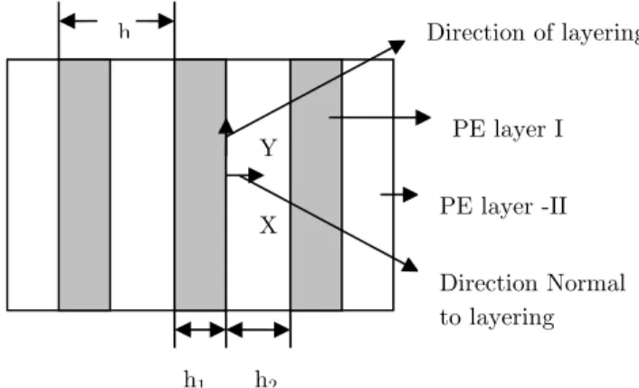
The piezoelectric layered (PE) structure is shown in Figure 1. The composite structure comprises of piezoelectric layers bonded perfectly alternatively of two different materials. These bonded layered have thickness of h1 and h2 respectively. Shear wave propagation is considered to be propagating either in direction normal to layering i.e. in positive direction of x axis or in direction of layering i.e. in posi-tive direction of y axis with poling direction taken along the z axis.
Figure 1: Schematic of periodic Piezoelectric -Piezoelectric (PE layer I, PE layer II) Layered Structure. Y
X
h1 h2
PE layer I
PE layer -II
h Direction of layering
Latin American Journal of Solids and Structures 11 (2014) 2483-2496 For shear wave propagating in x-y plane, the constitutive system of equations refereed to piezoelectric-piezoelectric interface can be written as (Qian et al. 2004):
ij ijkl kl kij k
j jkl kl jk k
c e E
D e E
s e
e
ì = - ü
ï ï
ï ï
í ý
ï = + ï
ï ï
î þ (1)
ij ijkl kl kij k
j jkl kl jk k
c e E
D e E
s e
e
ì = ¢ - ¢ ü
ï ï
ï ï
í ¢ ¢ ý
ï = + ï
ï ï
î þ (2)
Where σij, εij are stress and strain sensor, Dj, and Ek are displacement and electric field intensity. cijkl,
c'ijkl, ekij, e'kij, ϵjk, ϵ'jk are elastic, piezoelectric and dielectric constants for piezoelectric mediums respec-tively.
The motion equation for PE-I and PE-II can be represented in equation (3) as (Lee 2004 and Sun et al. 1968)
,
, 0
ij j i
i j u D
s r
ì = ü
ï ï
ï ï
í ý
ï = ï
ï ï
î þ
(3)
The strain tensor εij and electric field intensity Ei can be represented as
, ,
1
( )
2
ij j i i j
i
i
u u
E
x
e
j
ì ü
ï ï
ï = + ï
ï ï
ï ï
ï ï
í ¶ ý
ï ï
ï = - ï
ï ï
ï ¶ ï
ï ï
î þ
(4)
Where ui and r represents the mechanical displacement in ith direction and mass density. Electrical potential function can be expressed as j.
The constitutive system of equations for PE-I media are
11 12 13 31 12 11 12 31 12 12 11 33
44 15 44 15 44
15 11 15 11
31 31 33 33
2
2
2
2
+
2
+
+
x x y z z
y x y z y
x x y z x
zy zy y
zx zy y
xy xy
x x x
y y y
z x y z z
c
c
c
e E
c
c
c
e E
c
c
c
e E
c
e E
c
e E
c
D
e
E
D
e
E
D
e
e
e
E
s
e
e
e
s
e
e
e
s
e
e
e
t
e
t
e
t
e
e
e
e
e
e
=
+
+
-=
+
+
-=
+
+
-=
-=
-=
=
=
=
+
+
Latin American Journal of Solids and Structures 11 (2014) 2483-2496 The constitutive system of equations for PE-II media are
11 12 13 31
12 11 12 31
12 12 11 33
44 15
44 15
44
15 11
15 11
31 31 33
2 2 2 2 + 2 + +
x x y z z
y x y z y
x x y z x
zy zy y
zx zy y
xy xy
x x x
y y y
z x y z
c c c e E
c c c e E
c c c e E
c e E
c e E
c
D e E
D e E
D e e e
s e e e
s e e e
s e e e
t e
t e
t e
e e
e e e
¢ ¢ ¢ ¢ = + + -¢ ¢ ¢ ¢ = + + -¢ ¢ ¢ ¢ = + + -¢ ¢ = -¢ ¢ = -¢ = ¢ ¢ = ¢ ¢ = ¢ ¢ ¢ ¢ = + +
33Ez
(6)
Where 11 12 11 12
44 44
(c - c ) (c - c )
c = , c =
2 2
¢ ¢
¢
For shear wave propagation, the mechanical displacement and electrical potential function components in x, y and z direction can be expressed as
0, 0, ( , , ), ( , , )
u = u = w =w x y t j=jx y t .
Eliminating u and E from the equation (5) and (6), we get the system of equations (7) and (8)
2 2 2 2 2
1 1 1 1 1
44 2 2 15 2 2 2
2 2 2 2
1 1 1 1
15 2 2 11 2 2 0
w w w
c e
x y x y t
w w
e
x y x y
j j
r
j j
ì æ ö æ ö ü
ï ç¶ ¶ ÷ ç¶ ¶ ÷ ¶ ï
ï ç + ÷+ ç + ÷= ï
ï ç ÷ ç ÷ ï
ï ç ÷÷ ç ÷÷ ï
ï è¶ ¶ ø è¶ ¶ ø ¶ ï
ï ï
í æ ö æ ö ý
ï ç¶ ¶ ÷ ç¶ ¶ ÷ ï
ï ç + ÷- ç + ÷= ï
ï ç ÷ ç ÷ ï
ï ç ÷÷ ç ÷÷ ï
ï è¶ ¶ ø è¶ ¶ ø ï
ï ï
î þ
(7)
2 2 2 2 2
2 2 2 2 2
44 2 2 15 2 2 2
2 2 2 2
2 2 2 2
15 2 2 11 2 2 0
w w w
c e
x y x y t
w w
e
x y x y
j j
r
j j
ì æ ö æ ö ü
ï ç¶ ¶ ÷ ç¶ ¶ ÷ ¶ ï
ï ¢ ç + ÷+ ¢ ç + ÷= ¢ ï
ï ç ÷ ç ÷ ï
ï ç ÷÷ ç ÷÷ ï
ï è¶ ¶ ø è¶ ¶ ø ¶ ï
ï ï
í æ ö æ ö ý
ï ç¶ ¶ ÷ ç¶ ¶ ÷ ï
ï ¢ ç + ÷- ¢ ç + ÷= ï
ï ç ÷ ç ÷ ï
ï ç ÷÷ ç ÷÷ ï
ï è¶ ¶ ø è¶ ¶ ø ï
ï ï
î þ
(8)
For interface at x = 0 between PE-PE layers, the following boundary conditions must satisfy as
1 2 1 2
1 2 1 2
(0, y) (0, y), (0, y) (0, y) (0, y) (0, y), D (0, y) D (0, y)
zx zx x x
w w j j
t t
= =
= = (9)
For all interfaces between PE-PE layers, the following boundary conditions must be satisfied as follow
1 1 2 2 1 1 2 2
1 1 2 2 1 1 2 2
( , ) ( , ), ( , ) ( , ) ( , ) ( , ), ( , ) ( , )
zx zx x x
w h y w h y h y h y
h y h y D h y D h y
j j
t t
= - =
Latin American Journal of Solids and Structures 11 (2014) 2483-2496
3 SOLUTION
We will discuss the two cases for propagation of shear waves. The system of equations (7) and (8) is solved for these two cases of propagation behavior.
3.1 Propagation along the direction normal to the layering
For shear wave propagating along the positive direction of x axis, solution of system of equations (7) and (8) can be expressed in following form
( )
( )
( )( )
( )
( )1 1
1 1
, e
, e
ik x ct
ik x ct
w x t W x
x t x
j
-=
= F (11)
( )
( )
( )( )
( )
( )2 2
2 2
, e
, e
ik x ct
ik x ct
w x t W x
x t x
j
-=
= F (12)
Where k is wave number, c is propagation velocity of shear wave, i = -1.
( )
( )
( )
( )
1 , 2 , 1 , 2
W x W x F x F x are some undetermined functions. Substituting equation (11) and (12) in (7) and (8) we get
(
)
(
)
(
)
(
)
2 2 2 2
44 1 1 1 15 1 1 1 1
2 2
15 1 1 1 11 1 1 1
2 2
2 2 0
c W ikW k W e ik k k c W
e W ikW k W ik k
r
¢¢+ ¢- + F +¢¢ F - F¢ =
-¢¢+ ¢- - F +¢¢ F - F¢ = (13)
(
)
(
)
(
)
(
)
2 2 2 2
44 2 2 2 15 2 2 2 2
2 2
15 2 2 2 11 2 2 2
2 2
2 2 0
c W ikW k W e ik k k c W
e W ikW k W ik k
r
¢ ¢¢+ ¢- + ¢ F +¢¢ F - F¢ = - ¢
¢ ¢¢+ ¢- -¢ F +¢¢ F - F¢ = (14)
The solution of equations (13) and (14) can be determined as
( ) ( )
(
)
(
( ) ( ))
1
1 / 1 /
1 1 1
1 / 1 /
15
1 1 1 1
11
e e
e e e
sh sh
sh sh
c c ikx c c ikx
c c ikx c c ikx
ikx
W G H
e
G H x G H
- +
-- +
-F
= +
¢ ¢
= + + +
(15)
( ) ( )
(
)
(
( ) ( ))
1 / 1 /
2 2 2
1 / 1 /
15
2 2 2 2 2
11
e e
e e e
sh sh
sh sh
c c ikx c c ikx
c c ikx c c ikx
ikx
W G H
e
G H x G H
¢ ¢
- +
-¢ ¢
- +
-= +
¢ ¢ ¢
F = + + +
¢
(16)
2 2
11 44 15 11 11 44 15 11
( ) / , ( ) /
sh sh
c = c +e r c¢ = ¢ ¢c +e¢ r¢ ¢
Latin American Journal of Solids and Structures 11 (2014) 2483-2496
The complete solution of mechanical displacement and electrical function in PE-PE interface can be obtained by substituting equation (15) and (16) in (11) and (12) which can be expressed in following form as
( ) ( ) ( )
(
)
(
( ) ( ))
( )
1 / 1 /
1 1 1
1 / 1 /
15
1 1 1 1 1
11
( , ) e e
( , ) e e e
e
e
sh sh
sh sh
c c ikx c c ikx
c c ikx c c ikx
ikx
ik x ct
ik x ct
w x t G H
e
x t G H x G H
j - + -- + -é ù
= ê + ú
ë û
é ù
ê ¢ ¢ ú
=ê + + + ú
ë û (17)
( )
( ) ( ) ( )( )
(
)
(
( ) ( ))
( )
1 / 1 /
2 2 2
1 / 1 /
15
2 2 2 2 2
11
, e e e
, e e e
e
sh sh
sh sh
c c ikx c c ikx ik x ct
c c ikx c c ikx
ikx
ik x -ct
w x t G H
e
x t G H x G H
j ¢ ¢ - + - - -¢ ¢ - + -é ù
= ê + ú
ë û
é ¢ ù
ê ¢ ¢ ú
= ê + + + ú
¢
ë û (18)
3.2 Propagation along the direction of the layering
For the wave propagation in positive direction of y axis, the mechanical displacement and electrical potential function represented as
(
)
( )
( )(
)
( )
( )1 1
1 1
, , e
, , e
ik y ct
ik y ct
w x y t W x
x y t x
j
-=
= F (19)
(
)
( )
( )(
)
( )
( )2 2
2 2
, , W x e , , x e
ik y ct
ik y ct
w x y t x y t
j
-=
= F (20)
The complete solution of mechanical displacement and electrical function is obtained and represented as system of equations in (21) and (22)
( )
(
)
( )1 1
1 1
1 1 1
15
1 1 1 1 1
11
( , , ) e e e
( , , ) e e e e e
ik y ct
ib x ib x
ik y ct
ib x ib x
kx kx
w x y t G H
e
x y t G H G H
j -é ù
=êë + úû
é ù
ê ¢ ¢ ú
=ê + + + ú
ë û
(21)
(
)
( )(
)
(
)
(
)
( )2 2
2 2
2 2 2
15
2 2 2 2 2
11
, , e e e
, , e e e e e
ik y ct
b x b x
ik y ct
b x b x
kx kx
w x y t G H
e
x y t G H G H
j -é ù
= êë + úû
é ¢ ù
ê ¢ ¢ ú
= ê + + + ú
¢
ë û
(22)
Where 2 2
2 2
1 1, 12
sh sh
c c
c c
Latin American Journal of Solids and Structures 11 (2014) 2483-2496
4 SHEAR WAVE PROPAGATION AND DISPERSION RELATION
4.1 Propagation along the direction normal to the layering
Substituting the equations (17) and (18) in equations (5) and (6) gives
( ) ( )
(
)
( )( )
1 / 1 /
-1 15 1 1 1
-1 11 1
e e e e
e e
sh sh
c c ikx c c ikx ik x ct
ikx zx
sh ik x ct ikx x
ikcP
e H G H
c
D H
t - - +
-é ù
ê ¢ ú
= ê + - ú
ë û ¢ = - (23) ( ) ( )
(
)
( ) ( )1 / 1 /
-1
2 15 2 2 2
-2 11 2
e e e e
e e
sh sh
c c ikx c c ikx ik x ct
ikx zx
sh ik x ct ikx x
ikcP
e H G H
c
D H
t - - + ¢ - - ¢
-é ù
ê ¢ ¢ ú
= ê + - ú
¢
ë û
¢ ¢
= -
(24)
Where 11 44 215 11 44 152
1
11 11
,
c e c e
P = + P = ¢ ¢ + ¢
¢
Using the boundary conditions (9) in system of equations (17), (18), (23), and (24), provides the fol-lowing linear algebraic equations with undetermined coefficient as G1, G2, Gʹ1, Gʹ2, H1, H2, Hʹ1, and Hʹ2
( ) ( )
1 1 2 2
15 15 15 15
1 2 1 1 2 2
11 11 11 11
15 15
1 1 1 2 2 2
11 1 11 2
1 1 2 2
15 15
1 1 1 1 1 2 2
11 11 0 0 0 0 0 sh sh
i kh i kh
i i
i i ikh
G H G H
e e e e
G G G H G H
e c e c
G H H H QG QH
ikcP ikcP
H H
e G e H e G e H
e e
G h H e G e H e G h e
b b a a a a - + -+ - - = ¢ ¢ ¢- ¢+ + - - = ¢ ¢ ¢ ¢ - + - - + = ¢ ¢ ¢ - + = + - - = ¢+ ¢+ + - ¢+ ( ) ( ) ( ) ( ) 15 15
2 2 2
11 11
15 15
1 1 1 2 2 2
11 1 11 2
0
0
0
i kh i kh
ikh
i kh i kh
i i ikh
sh sh
ikh
e e
H e G e H
e c e c
H e G e H e H Qe G Qe H
ikcP ikcP
H e H
b b b b a a - + - + -¢ ¢ ¢ - - = ¢ ¢ ¢ ¢+ - - ¢- + = ¢ ¢ ¢ - + = (25)
For solving the linear algebraic equations, we have introduced the following factors
1, 2, 1sh,
sh sh sh
ckh ckh P c
Q w kc
c c Pc
a= b = = =
¢ ¢
For obtaining the solution of equations (25), the determinant of coefficients of 8x8 matrixes must be equal to zero. The determinant of system of equations (25) provides as (Christensen 1979 and Sun et al. 1968)
2
sin( )sin( ) + 2Qcos(hk) - 2Qcos( )cos( ) + Q sin( )sin( ) = 0a b a b a b
Latin American Journal of Solids and Structures 11 (2014) 2483-2496 The above equation can be represented in much simpler form
(
2)
1 2 1 2
sh sh sh sh
2
1 2 1 2
sh sh sh
1 + Q
ckh ckh ckh ckh
cos(hk) - cos cos + sin sin = 0
c c c c
ckh ckh ckh ckh
wh (1 + Q
cos - cos cos + sin sin
c c c c
2Q ) 2Q
¢ ¢
¢
æ ö÷ æ ö÷ æ ö÷ æ ö÷
ç ÷ ç ÷ ç ÷ ç ÷
ç ÷÷ ç ÷÷ ç ÷÷ ç ÷÷
ç ç ç ç
è ø è ø è ø è ø
æ ö æ ö æ ö
æ ö÷ ç ÷ ç ÷ ç ÷
ç ÷ ç ÷ ç ÷ ç ÷
ç ÷ ÷ ÷ ÷
ç ç ÷ ç ÷ ç ÷
è ø è ø è ø è ø csh¢ = 0 æ ö÷ ç ÷ ç ÷÷ çè ø
(27)
Where h=h1+h2 is total thickness of piezoelectric bonded layers. The equation (27) represents the dis-persion relation for shear wave propagating in direction normal to layering.
4.2 Propagation along the direction of the layering
For Shear wave propagation along the direction of layering, substitution of equation (21) and (22) in equation (5) and (6) provides the stress and electrical displacement component as
(
)
(
)
( )
(
)
( )1 1
1 1 1 1 15 1 1
1 11 1 1
-e e e e
e e
e
e
ib x ib x kx kx
zx
kx kx
x
ik y ct
ik y ct
ib P G H e k G H
D k G H
t -
-é ¢ ¢ ù
= êë - + + - + úû
¢ ¢ = - - + (28)
(
)
(
)
( )(
)
( ) 2 22 2 1 2 2 15 2 2
2 11 2 2
-e e e e
e e
e
e
b x b x kx kx
zx
kx kx
x
ik y ct
ik y ct
b P G H e k G H
D k G H
t -
-é ¢ ¢ ¢ ù
=êë - + + - + úû
¢ ¢ ¢
= - - +
(29)
Using the boundary conditions (10) in system of equation (21), (22), (28) and (29), provides the follow-ing linear algebraic equation with undetermined coefficient as G1, G2, Gʹ1, Gʹ2, H1, H2, Hʹ1, and Hʹ2
1 1 1 1 2 2 2 2
1 1 2 2
15 15 15 15
1 1 2 2 2 2
11 11 11 11
15 15 15 15
1 1 1 1 2 2 2 2
1 1 1 1
11 1 11 1 11 2 11 2
1 1 2 2
15 0 0 0 0 0
ib h ib h b h b h
G H G H
e e e e
G H G H G H
e k e k e k e k
G H G H QG QH G H
ib P ib P ib P ib P
G H G H
e G e H e G e H
e - -+ - - = ¢ ¢ ¢ ¢ + - - - - = ¢ ¢ ¢ ¢ ¢ ¢ ¢ ¢ - + - + + - + - = ¢- ¢- ¢ ¢+ ¢ ¢ = + - - =
1 1 1 1 1 1 2 2 2 2 2 2
1 1 1 1 1 1 2 2 2 2 2 2
15 15 15
1 1 1 1 2 2 2 2
11 11 11 11
15 15 15 15
1 1 1 1 2 2 2
1 1 1 1
0
ib h ib h kh kh kh kh b h b h
ib h ib h kh kh b h b h kh kh
e e e
e G e H e G e H e G e H e G e H
e k e k e k e k
e G e H e G e H e QG e QH e G e H
ib P ib P ib P ib P
- - - -- - - -¢ ¢ ¢ ¢ ¢ ¢ + + + - - - - = ¢ ¢ ¢ ¢ ¢ ¢ ¢ ¢ - + - + + - + -
1 1 2 2
2
11 1 11 1 11 2 11 2
0
0
kh kh kh kh
e- G e H e- G e H
=
¢- ¢- ¢ ¢+ ¢ ¢ =
(30)
Latin American Journal of Solids and Structures 11 (2014) 2483-2496
( )
( )
( )
( )
[
]
[
(
)
(
)
(
)
(
)
]
{
}
( )
( )
[
][
]
{
}
(
)
(
)
( )
( )
(
)
(
)
11 1 2 11 2 1 1 44 1 1 2 2 2 1 1 2 2
2
11 1 11 2 44 1 2 2 2 1 1 15 11 11
2 4
15 11 11 1 2 1 1 2 2
2
e sinh kh cosh kh + e sinh kh cosh kh r c cos b h sinh b h + P1r sin b h cosh b h
- e sinh kh + e sinh kh c r sinh(b h ) + P r sin(b h )1 2e e / e
- e e / e sinh kh sinh kh sinh b h sinh b h
- P 1
{
} ×
¢
¢ ¢ ¢
¢ ¢
é ù
ê ú
ë û
(
)
(
)
(
)
[
(
)
(
)
]
{
}
(
)
( )
( )
[
( )
( )
]
{
1111}
..2 2 2
2 44 1 1 1 2 2 44 1 2 1 1 2 2
2 2
11 11 1 2 11 1 2
r - c r sin b h sinh b h + 2c P r r1 cos b h cosh b h - 1
× e + e¢ sinh kh sinh kh + 2 ¢ cosh kh cosh kh - 1 = 0
(31)
2 2 2 2
1 1
1 2 2 2
2
, ,
sh sh
sh sh
c c c c P b
r r Q
Pb
c c
¢
-
-= = =
¢
Equation (31) known as the dispersion equation for shear wave propagating along the direction of lay-ering. The influence of layer thickness, volume fraction, existence of stop band and numerically analysis will be considered in preceding section.
5 NUMERICAL ANALYSIS AND DISCUSSION
The propagation characteristic of shear wave based on dispersion relation derived in equation (27) is investigated by numerically analysis carried out in this section for two different piezoelectric materials. The materials used in numerical calculation are PVDF and PZT-5H. Table 1 lists the properties of piezoelectric materials.
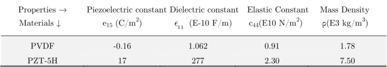
Properties Piezoelectric constant Dielectric constant Elastic Constant Mass Density Materials e15 (C/m2) (E-10 F/m) c44(E10 N/m2) ρ(E3 kg/m3)
PVDF -0.16 1.062 0.91 1.78
PZT-5H 17 277 2.30 7.50
Table 1: Material Properties used in Numerical Calculation
Latin American Journal of Solids and Structures 11 (2014) 2483-2496
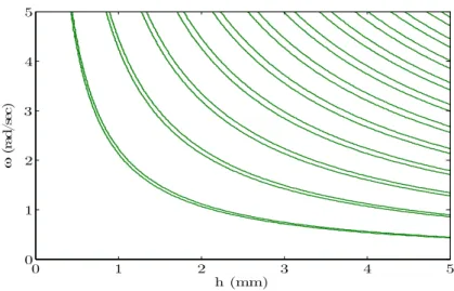
Figure 2: Circular frequency ω vs. h2 for h1=0.1mm.
Figure 3: Circular frequency ω vs. h1 for h2=0.1mm.
Figure 4: Circular frequency ω vs. total thickness h for h1=h2. h2 (mm)
(
rad
/s
ec
)
0 1 2 3 4 5
0 1 2 3 4 5
h1 (mm)
w
(
rad
/se
c)
0 1 2 3 4 5
0 1 2 3 4 5
h (mm)
(
rad
/s
ec
)
0 1 2 3 4 5
Latin American Journal of Solids and Structures 11 (2014) 2483-2496
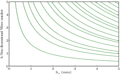
Figure 5: Wave number k vs. h2 for h1=0.1mm.
Figure 6: Wave number k vs. h1 for h2=0.1mm.
Figure 7: Wave number k vs. total thickness h for h1=h2. h2 (mm)
k N
on di
m
ens
io
na
l
W
av
e
num
be
r
0 1 2 3 4 5
0 1 2 3 4 5
h1 (mm)
k N
on
di
m
ens
io
na
l w
av
e nu
m
be
r
0 1 2 3 4 5
0 1 2 3 4 5
h (mm)
k N
on di
m
es
io
na
l W
av
e
num
be
r
0 1 2 3 4 5
Latin American Journal of Solids and Structures 11 (2014) 2483-2496
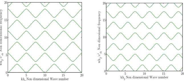
To study the variation pattern of wave number kh2 on ωh2/c'sh, we assumed a new variable volume fraction, which is defined as γ=h1/(h1+h2), where h1 and h2 are thickness of PE-PE layers in composite structure. The curves are plotted for different value of γ ranging from 0.2 -0.8 as depicted in figure 8 and 9. For propagation along the direction normal to layering, it is observed from the curves that number of stop bands increases with increase in value of volume fraction. But as the volume fraction increases, the decrease in width of stop band is observed from the curves shown below.
Figure 8: Stop band effect of propagation normal to layering for γ (a) 0.2 (b) 0.4.
Figure 9: Stop band effect of propagation normal to layering for γ (a) 0.6 (b) 0.8.
For investigating the influence of volume fraction on phase velocity, figure 10 (a) and (b) plotted for two values of circular frequency 1000 Hz and 1500Hz with h1 fixed at 1 mm. It is clearly observed from the curves, the phase velocity decrease gradually with increase in value of volume fraction γ. The curves are shown for wave propagation along the direction normal to layering.
kh2 Non dimensional Wave number
wh
2
/c
'sh
N
on d
im
ens
io
na
l f
re
qu
en
cy
0 5 10 15 20
0 5 10 15 20
kh2 Non dimensional Wave number
wh
2
/c
'sh
N
on dim
es
ion
al f
re
qu
enc
y
0 5 10 15 20
0 5 10 15 20
kh2 Non dimensional Wave number
wh
2
/c'
sh
N
on
di
m
ens
io
nal
f
re
que
nc
y
0 5 10 15 20
0 5 10 15 20
kh2 Non dimensional Wave number
wh
2
/c
'sh
N
on di
m
ens
io
na
l
fr
eq
ue
nc
y
0 5 10 15 20
Latin American Journal of Solids and Structures 11 (2014) 2483-2496
Figure 10:Phase velocity (c) vs. volume fraction (γ) for circular frequency (a) 1000 Hz (b) 1500 Hz.
6 CONCLUSIONS
In this paper, we have investigated Shear wave propagation in piezoelectric composite structure having two piezoelectric layers bonded together alternatively. The dispersion equations were obtained through analytical method for propagation along and in the direction of layering. The limitation of this investi-gation, we have assumed there was no initial stress present in either of the layers in piezoelectric com-posite structure. Future work can be done to study the propagation behavior in PE structures in the presence of initial stress. The numerical results obtained from this study, we draw following conclusions (a) When Shear wave propagates in direction normal to layering, the stop band effect exists and num-ber of stop band found to be increase with increase in volume fraction.
(b) For the case of wave propagation in direction of layering, no stop band exists.
(c) There is significant influence of volume fraction on the phase velocity. We found that, phase veloci-ty decreases subsequently with increase in volume fraction. So we conclude that there exists a linear relationship between volume fraction and phase velocity.
The results found to be useful in developing a new class of SAW sensor based on PVDF –PZT compo-site with improved response and higher sensitivity. This can be achieved by obtaining the desired propagation of shear wave by selecting the appropriate material, thickness, elastic constants and other boundary conditions.
References
Christensen, R.M.: Mechanics of Composite Materials, Wiley-Interscience, New York, (1979).
Du, J., Xian, K., Wang, J.: SH surface acoustic wave propagation in a cylindrically layered piezomagnetic /piezoelectric structure, Ultrasonics 49, 131–138 (2009).
0 0.2 0.4 0.6 0.8 1 0
500 1000 1500 2000 2500 3000 3500
Non dimensional Volume fraction
P
ha
se v
el
oci
ty
(
m
/s
)
0 0.2 0.4 0.6 0.8 1 0
1000 2000 3000 4000 5000
Non dimensional Volume fraction
P
ha
se v
el
oci
ty
(
m
/s
Latin American Journal of Solids and Structures 11 (2014) 2483-2496
Du, J., Jin, X., Wang, J., et al.: SH wave propagation in a cylindrically layered piezoelectric structure with initial stress, Acta Mechanica 191, 59–74 (2007).
Dua, J., Xian, K., Wanga, J., et. al.: Love wave propagation in piezoelectric layered structure with dissipation, Ultrason-ics 49, 281-286 (2009).
Huang, Y., Li, X.F., Lee, K.Y., et.al.: Interfacial shear horizontal (SH) waves propagating in a two-phase piezoelec-tric/piezomagnetic structure with an imperfect interface, Philosophical Magazine Letters 89, 95–103 (2009).
Huang, Y., Li, X.F, et.al.: Interfacial waves in dissimilar piezoelectric cubic crystals with an imperfect bonding. IEEE Transactions on Ultrasonics, Ferroelectrics, and Frequency Control 58, 1261–1265 (2011).
Lee, U.: Spectral Element Method in Structural Dynamics, Inha University Press, Korea, (2004)
Melkumyan, A., Mai, Y.W., et.al.: Influence of imperfect bonding on interface waves guided by piezoelec-tric/piezomagnetic composites, Philosophical Magazine 88, 2965–2977 (2008).
Nie, G., Liu, J., Fang, Q., et.al.: An Shear horizontal (SH) waves propagating in piezoelectric–piezomagnetic bilayer system with an imperfect interface, Acta Mechanica 223, 1999–2009 (2012).
Pang, Y., Liu, J., Wang, Y., et.al.: Wave propagation in piezoelectric/piezomagnetic layered periodic composites, Acta Mechanica Solida Sinica 21, 483-490 (2008).
Piliposian, G.T., Avetisyan, A.S., Ghazaryanb, K.B., et.al.: Shear wave propagation in periodic phononic/photonic pie-zoelectric Medium, Wave Motion 49, 125–134 (2012).
Pyatakov, P.A.: Shear Horizontal Acoustic Waves at the Boundary of Two Piezoelectric Crystals Separated by a Liquid Layer, Acoustical Physics 47, 739–745 (2001).
Qian, Z., Jin, F., Wang, Z., et. al.: Dispersion relations for SH-wave propagation in periodic piezoelectric composite layered structures, International Journal of Engineering Science 42, 673–689 (2004).
Qian, Z., Jin, F., Wang, Z., et. al.: Love waves propagation in a piezoelectric layered structure with initial stresses, Acta Mechanica 171, 41–57 (2004).
Rahman, N.U., Alam, M.N.: Finite element modeling for buckling analysis of hybrid piezoelectric beam under electrome-chanical loads, Latin American Journal of Solids and Structures 11, 770-789 (2014).
Singh, B.M., Rokne, J.: Propagation of SH waves in layered functionally gradient piezoelectric–piezomagnetic structures, Philosophical Magazine 93, 1690-1700 (2013).
Sun, C.T., Achenbach, J.D., Herrmann, G., et.al.: Continum theory for laminated medium, Journal of applied mechanics 35, 467-473 (1968).
Vashishth, A.K., Dahiya, A.: Shear waves in a piezoceramic layered structure, Acta Mechanica 224, 727–744 (2013).
Vashishth, A.K., Gupta, V.: Vibrations of porous piezoelectric ceramic plates, Journal of Sound and Vibration 325, 781– 797 (2009).
Wang, H, M., Zhao, Z, C.: Love waves in a two-layered piezoelectric/elastic composite plate with an imperfect interface, Archive of Applied Mechanics 83, 43–51 (2013).