The influence of the mode II fracture energy on the behaviour of
composite plate reinforced concrete
P. Neto
ESTB/IPS, Barreiro, Portugal
J. Alfaiate
Dep. Eng. Civil and ICIST, IST, Lisboa, Portugal
J. R. Almeida
Dep. Eng. Civil and UNIC, FCT/UNL, Caparica, Portugal
E. B. Pires & J. Vinagre
Dep. Eng. Civil and ICIST, IST, Lisboa, Portugal
ABSTRACT: In this paper, the finite element method is used to analyse the behaviour of concrete externally strengthened by sheets of carbon fibre reinforced polymer (CFRP). The bond between concrete and CFRP is modelled by a discrete approach using interface elements. The mechanisms involved in the behaviour of externally reinforced concrete specimens are complex, the global strength of the specimen being governed by the strength of each individual material as well as by the adhesion properties conferred by the epoxy. It is observed in experiments that, in most cases, failure occurs due to the loss of cohesion of a portion or lamina of concrete attached to the epoxy-fibres layers, the latter remaining intact. In this paper, the results of numerical simulations of bond tests are presented, aiming to contribute for a better understanding, in qualitative and quantitative terms, of mode II fracture energy in concrete and its influen-ce on the behaviour of the interfainfluen-ce concrete-FRP.
Keywords: concrete, FRP, bond, interface, mode II fracture energy. 1 INTRODUCTION
In recent years, the use of composite materials applied to the external strengthening of concrete structures has increased. However, the behaviour of such structures is not yet very well characterized, namely with respect to the bonding conditions between the concrete and the strengthening material. Some works on this topic have been carried out (Sonobe et al. 1997, Chaallal et al. 1998, Saadatmanesh & Malek 1998, FIB 2001). Nevertheless, only a limited set of design rules has been proposed and in general the application of FRP strengthening is much dependent on the manufacturers specifications.
The strength of a glued concrete-FRP bond is
determined by the following three parameters: i) shear strength of the superficial concrete layer, ii) adhesive strength of the epoxy resin and iii) interlaminar strength of the FRP. It is observed in experiments that, in most cases, failure occurs due to the loss of cohesion of a portion or lamina of concrete attached to the epoxy-fibre layers, the latter remaining intact. In these cases, it is assumed that the energy dissipated per unit of cracked surface is equal to the fracture energy of concrete in mode II, denoted by GFII.
Several experimental and numerical tests have been carried out to study mixed mode fracture, namely the significance of GFII and its
quantifi-cation. However, the definition of this material parameter is still not well established and the
nume-been contradictory. Bazant & Pfeiffer (1986) and Ozbolt et al. (1998) proposed for GFII values about
25 times greater than GF. Alfaiate & Pires (1998)
performed numerical analyses of notched beams subjected to shear and did not detect any significant differences on the value of the failure load when GFII/GF varied from 1 to 100. Such result was
confirmed by Gálvez et al. (1998), who carried out a similar study. Täljsten (1994) performed a set of experimental tests for determining both values of GF and GFII. The mode II fracture energy was
determined submitting a concrete specimen to both compression and shear. The values determined for GFII were found to be 10 times greater than the
value of GF. However, since the specimens were
also submitted to high compressive stresses, the amount of energy dissipated should be higher than the value corresponding to pure shear testing.
In this paper, the adhesion between the CFRP sheets and the concrete is modelled using a discrete crack approach based on non-linear fracture mechanics (Hillerborg et al. 1976). The bond between concrete and CFRP is modelled by inter-face elements with zero initial thickness. The shear stresses developed at these elements are dependent on the relative sliding displacement between the strengthening material and the concrete surface, according to a local constitutive relationship. The material properties that characterize the interface, namely the shear stiffness, the cohesion and the fracture energy in mode II, are obtained from a parametric study with the objective of reproducing experimental data obtained in CFRP pullout tests. From the analysis of the values obtained numeri-cally, it is possible to conclude that mode II fracture plays an important role on these tests and a range of values is proposed for GFII. It is expected that this
work may contribute for a better comprehension of the stress transfer mechanisms between the concrete and the strengthening material, particu-larly with respect to the qualitative and quantitative definition of mode II fracture of concrete.
2 EXPERIMENTAL TESTING
For characterizing the behaviour of the bond between CFRP and concrete, Travassos (2003) conducted an experimental work that included a set of shear tests on a concrete joint strengthened with a layer of CFRP. In these tests, unidirectional
in the CFRP sheets, several extensometers were placed along the bond length. The concrete specimens tested were 400 mm long and had a rectangular cross-section of 200 mm by 200 mm. The strengthening material had a width of 80 mm and was applied on the larger face of the specimen. Three different bond lengths were considered: 200 mm, 275 mm and 350 mm. Travassos also carried out bending tests. The beams tested had a 200 × 200 mm2 cross section, a span of 910 mm and
were notched at midspan in order to better characterize the bond between concrete and CFRP.
The carbon fibre sheets were impregnated in situ with resin. These fibres had a density of 1.8 g/cm3
and a weight per unit area of 200 g/m2. From these values, it was possible to deduce that the fibre thickness was equal to 0.111 mm. The nominal values for the Young’s modulus and the ultimate tensile strain of the CFRP were 240 GPa and 1.55 %, respectively. Mean values of 36.4 MPa, 2.8 MPa and 31.6 GPa, for the compressive strength, tensile strength and Young’s modulus of concrete, respectively, were obtained experimentally.
3 NUMERICAL MODELLING 3.1 Constitutive relationships
The tensile behaviour of CFRP may be assumed as linear elastic until failure. Hence, a linear stress-strain relationship was considered for this material in the numerical model. Considering the nature of the tests and consequently the stresses installed in the concrete, a linear elastic and isotropic constitu-tive relationship was also adopted for the concrete. The bond between concrete, resin and CFRP was modelled through interface elements of zero initial thickness. The behaviour of such elements was modelled using the fictitious crack model originally formulated for mode I fracture by Hillerborg et al. (1976). For the relationship between the shear stress, τ, and the slip at the joint edges, s, a law with a linear softening branch was initially considered. However, a poor match between numerical and experimental results was obtained when using this relationship. Hence, a bilinear relationship, often considered for mode I fracture (Petersson 1981), was adopted. The material parameters that characterize the interface behaviour
Figure 1: Shear and bending tests: finite element meshes adopted.
3.2 Algorithm
The numerical analysis was performed using the finite element method. The elements adopted were 4-node isoparametric for the concrete and linear 2-node for the strengthening material. The bond between concrete, resin, and CFRP was modelled by linear interface elements. The specimen response was determined with displacement control through an incremental and iterative procedure, according to the following algorithm:
1. Calculation of the incremental stiffness matrix of the structure Kt;
2. Solving the system of equations Kt∆∆∆∆u = ∆λF,
where ∆∆∆∆u is the incremental displacement vector, ∆λ is the load increment size and F is the nodal force vector;
3. Evaluation of the internal forces Fi. The
Newton-Raphson and the arc length methods are used for obtaining convergence towards a solution without unbalanced forces. If equilibrium is not reached within a prescribed tolerance, a new iteration must be performed; otherwise proceed to step 4;
4. Update of the total variables, application of another load increment ∆λ and return to step 1. The finite element meshes adopted for both types of tests are schematically represented in Figure 1.
3.3 Numerical analysis
As mentioned above, the constitutive relationship of the interface concrete-CFRP is defined by three parameters: the elastic shear stiffness, the cohesion
0.95 1.00 1.05 1.10 0 1000 2000 3000 kint (MPa/mm) Pu/Pulim
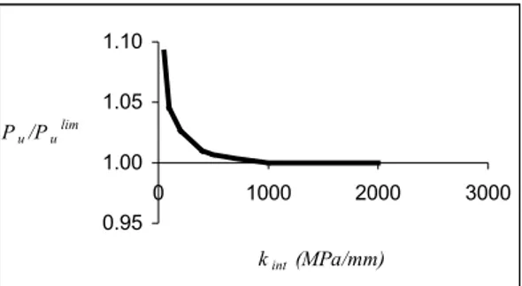
Figure 2: Relationship between ratio Pu/Pulim and interface stiffness kint.
and the fracture energy in mode II. Figure 2 represents a relationship, obtained numerically, between the elastic stiffness of the interface kint and
the ratio Pu/Pulim. In this Figure, Pu is the ultimate
load and Pulim is the value of the ultimate load when
kint tends to infinity. It is observed that Pu/Pulim
decreases slightly when kint increases. In fact, since
the load is applied to the CFRP and failure takes place in the concrete, when the interface stiffness increases the stresses transmitted to concrete become larger; as a consequence, failure will occur for a lower load level.
The first part of the curve in Figure 2, where the ultimate load varies more significantly, corresponds to small values of kint. For this situation, it is not
possible to mobilize a significant level of shear strain in the concrete, since this material remains within the elastic domain. Since it was experimentally checked that the ultimate load is reached in the non-linear range, the shear stiffness to be considered should not be too low. The value adopted for the subsequent analyses was kint = 1000 MPa/mm, allowing the consideration of
a non-linear behaviour for sufficiently large loads. The adoption of this value makes the ultimate load independent of kint; in fact, according to Figure
2, for kint ≥ 1000 MPa/mm, the numerical value of
the ultimate load is approximately constant. After fixing a value for kint, the influence of the
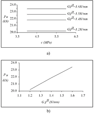
cohesion and of mode II fracture energy on the ultimate load was analysed. Figure 3a) shows the variation of the numerical ultimate load with the cohesion, for a set of values of GFII. It can be seen
that, if the fracture energy does not vary, the cohesion does not affect the ultimate strength.
Figure 3: Variation of ultimate load with cohesion and fracture energy.
The variation of the ultimate load with the fracture energy is represented in Figure 3b). It is observed that, within the limited range adopted for GFII, this
variation is approximately linear, irrespectively of the value adopted for the cohesion.
In order to assess the influence of each parameter on the distribution of strains in the CFRP, a sensitivity study was carried out in which each parameter was varied independently about a reference solution defined by: kint = 500 MPa/mm,
c = 4 MPa and GFII = 1.5 N/mm. The results of this
study are summarized in Figure 4. It can be observed that the elastic stiffness of the interface has only some influence in the zone of the strain diagram with more pronounced curvature, in which the behaviour is predominantly elastic. The cohesion and the fracture energy are the parameters that produce larger variations of the CFRP strains. It is also seen that lower values of kint, c and GFII
lead to a more flexible solution and consequently to larger strains at the bond length.
In the experiments carried out, a mean value of approximately 22.5 kN was found for the ultimate load Pu. This enabled the definition of an estimate
of 1.5 N/mm for the value of G II (see Figure 3b)).
Figure 4: CFRP strains at the bond length: influence of kint, c and GFII.
determined experimentally, such as the longitudinal strains at the interface concrete-CFRP. In fact, considering the equilibrium of an element of CFRP of length ∆x one can write:
τ = ∆∆xε tE (1) where t and E are the thickness and the Young’s modulus of the CFRP, respectively.
In view of Equation (1) and knowing that τmax = c
in pure shear, it is possible to assume, based on the experimental results, a value of 5.0 MPa for the cohesion. Additionally, it was verified that the adoption of this value for the cohesion provides a good fit between the numerical and experimental strain diagrams.
Having adopted kint = 1000 MPa/mm, c=5.0 MPa
and GFII = 1.5 N/mm, the computational simulations
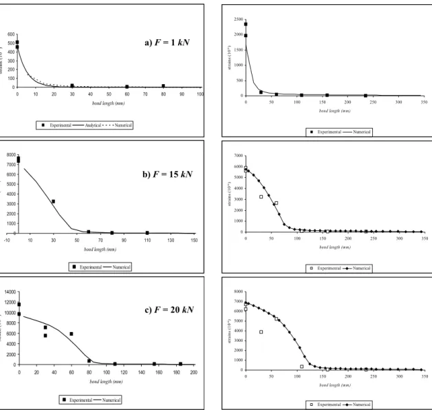
of the tests were then performed. Figure 9 shows the corresponding numerical and experimental values of strains along the bond length for several load levels. In general, the match achieved was quite satisfactory. In Figure 5(a), which corresponds to the lowest load level, an additional comparison with elastic solutions obtained analyti-cally (Täljsten 1994 and Bizindavyi & Neale 1999) is made. A reasonable agreement was also observed in this case, confirming that the value adopted for the elastic stiffness, kint, is indeed adequate.
Two bending tests were also numerically analy-sed. One test had two CFRP layers and the other had three CFRP layers. The same material parameters derived form the pullout tests were adopted and mode I fracture at the interface was neglected. In Figures 5 and 6 the numerical and experimental values of strains along the bond length for several load levels are presented for both
0 1000 2000 3000 4000 5000 6000 0 20 40 60 80 100 120 140 160 180 bond length (mm) st ra in s ( 1 0 -6) 2kint c /2 2c 2GFII GFII/2 kint/2
0 100 200 300 400 500 600 0 10 20 30 40 50 60 70 80 90 100 bond length (mm) st ra in s (1 0 -6)
Experimental Analytical Numerical
0 1000 2000 3000 4000 5000 6000 7000 8000 -10 10 30 50 70 90 110 130 150 bond length (mm) st ra in s ( 1 0 -6) Experimental Numerical 0 2000 4000 6000 8000 10000 12000 14000 0 20 40 60 80 100 120 140 160 180 200 bond length (mm) st rai ns (1 0 -6) Experimental Numerical
Figure 5: Strains obtained numerically and experimentally at the bond length for loads: (a) F = 1 kN; (b) F = 15 kN; (c) F = 20 kN.
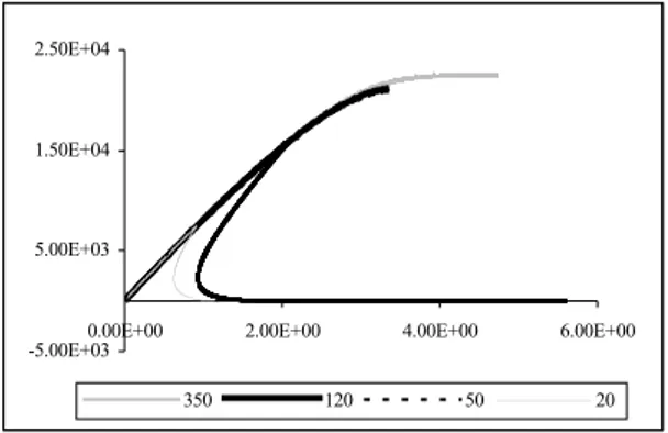
The influence of the bond length lb on the
load-displacement curve is depicted in Figure 7. It can be observed that the maximum load increases with lb if this parameter is kept below a certain limit,
designated as the effective bond length, leff. An
effective bond length of about 120 mm was found in the example analysed herein. For higher values of lb,the ultimate load tends to a plateau; this is due
to the fact that shear stresses can be transferred along the interface until total debonding occurs. Conversely, for lb below the effective bond length,
this mechanism is no longer possible and a strong snap-back is obtained as shown in Figure 7.
0 500 1000 1500 2000 2500 0 50 100 150 200 250 300 350 bond length (mm) st ra in s ( 1 0 -6) Experimental Numerical 0 1000 2000 3000 4000 5000 6000 7000 0 50 100 150 200 250 300 350 bond length (mm) st ra in s ( 1 0 -6) Experimental Numerical 0 1000 2000 3000 4000 5000 6000 7000 8000 0 50 100 150 200 250 300 350 bond length (mm) st ra in s ( 1 0 -6) Experimental Numerical
Figure 6 – Two layer beam: strains obtained numerically and experimentally at the bond length.
4 CONCLUSIONS
The research focused on the computational modelling, based on non-linear fracture mechanics, of the behaviour of the bond between concrete and CFRP strengthening. Through a parametric study performed on experimental data collected from CFRPpullout tests, it was possible to identify three material properties which define the constitutive relationship of the interface: the elastic shear stiffness of the interface, kint, the concrete cohesion,
c, and the mode II fracture energy of concrete, GFII.
It was found that the stiffness kint is especially
important in the elastic domain; for values of kint
a) F = 1 kN
b) F = 15 kN
-5.00E+03 5.00E+03 1.50E+04 2.50E+04
0.00E+00 2.00E+00 4.00E+00 6.00E+00
350 120 50 20
Figure 7: Load-displacement curves for different bond lengths.
above 1000 MPa/mm, the structural response is non-linear and practically independent from this parameter. Hence, it was decided to adopt kint = 1000 MPa/mm, considering also that this
value led to a fair agreement between the experimental and the numerical results. The cohesion c affects essentially the strain diagram. In fact, it was shown that, for a given value of GFII, the
ultimate load does not vary with the cohesion. The value of c was set equal to 5 MPa, in order to obtain a good approximation with the strain diagrams in the CFRP measured experimentally. It was also found that, for constant values of the cohesion, the ultimate load depends almost exclusively on the fracture energy GFII. Based on
the experiments, a value of GFII equal to 1.5 N/mm
was adopted. This leads to a ratio GFII/GF of 15,
since a value for GF equal to 0.1 N/mm is usually
adopted for ordinary concrete (Petersson 1981). It is interesting to point out that this ratio lies within the range proposed by Täjlsten (1994).
The numerical simulation of the bending tests enabled further validation of the numerical model and of the values adopted for the parameters. The numerical results fitted rather well the experimental data. It was found that mode I fracture did not have any significant influence on the structural response. Moreover, from this analysis, it was observed that tests with multiple CFRP layers can also be modelled accurately.
Finally, it may also be concluded that: i) consideration of mode II is essential in order to approximate correctly the experimental data using a discrete crack formulation, ii) the value of the mode II fracture energy cannot be neglected when
This work was developed in the framework of the project “Study of Bond between Concrete and Composite Materials for Strengthening” – POCTI/ECM/36043/2000, financed by Fundação para a Ciência e a Tecnologia (FCT).
REFERENCES
Alfaiate J. & Pires E.B. 1998. Mode I and mixed mode non-prescribed discrete crack propagation in concrete. In: Mihashi H., Rokugo K., editors. Proceedings of FRAMCOS-3, vol.2: 739-748.
Alfaiate J. & Pires E.B. 1999. Mixed mode fracture in concrete. In: Aliabadi M.H., editor. Proceedings of the International Conference on Fracture and Damage Mechanics: 381-392. Bazant Z.P. & Pfeiffer P.A. 1986. Shear fracture tests of
concrete. Materials and Structures, 19: 111-121.
Bizindavyi L. & Neale K.W. 1999. Transfer lengths and bond strengths for composites bonded to concrete. ASCE - Journal of Composites for Construction, 3(4): 153-160.
Chaallal O., Nollet M.J. & Perraton D. 1998. Strengthening of reinforced concrete beams with externally bonded fiber-reinforced-plastic plates: design guidelines for shear and flexure. Canadian Journal of Civil Engineering, 25(4): 692-704.
FIB (CEB-FIP) 2001. FIB Technical report on the design and use of externally bonded fibre reinforced polymer reinforcement (FRP EBR) for reinforced concrete structures - externally bonded FRP reinforcement for RC structures. Fedération International du Béton, Bulletin 14.
Gálvez J.C., Cendón D.A., Planas J., Guinea G.V. & Elices M. 1998. Fracture of concrete under mixed loading - experimental results and numerical prediction. In: Mihashi H., Rokugo K., editors. Proceedings of FRAMCOS-3, vol.2: 729-738.
Hillerborg A., Modeer M. & Petersson P.-E. 1976. Analysis of crack formation and crack growth in concrete by means of fracture mechanics and finite elements. Cement and Concrete Research, vol. 6: 773-782.
Ozbolt J., Reinhardt H.W. and Xu S. 1998. Numerical studies of the double-edge notched mode II geometry. In: Mihashi H., Rokugo K., editors. Proceedings of FRAMCOS-3, vol.2: 773-782.
Petersson P.-E. 1981. Crack growth and development of fracture zones in plain concrete and similar materials. PhD. Thesis, Report TVBM-1006, Division of Building Materials, Lund Institute of Technology.
Saadatmanesh H. & Malek A.M. 1998. Design guidelines for flexural strengthening of RC beams with FRP plates. ASCE - Journal of Composites for Construction, 2(4): 158-164. Sonobe Y., Fukuyama H., Okamoto T., Kani N., Kimura K.,
Kobayashi K., Masuda Y., Matsuzaki Y., Mochizuki S., Nagasaka T., Shimizu A., Tanano H., Tanigaki M. & Teshigawara M. 1997. Design guidelines of FRP reinforced concrete building structures. ASCE - Journal of Composites for Construction, 1(3): 90-115.
Täljsten B. 1994. Plate bonding – strengthening of existing concrete structures with epoxy bonded plates of steel or fibre