Brazilian Microwave and Optoelectronics Society-SBMO received 19 Sep 2017; for review 22 Sep 2017; accepted 29 Jan 2018
Brazilian Society of Electromagnetism-SBMag © 2018 SBMO/SBMag ISSN 2179-1074 Abstract— Faraday and Kerr effects as well as the extraordinary
optical transmission in a structure that combines magneto-optical and plasmonic properties are studied. The planar structure consists of four layers, namely, dielectric layer, metal strips, once again dieletric layer and magneto-optic one. The magneto-optical layer is magnetized by a DC magnetic field normal to it. Our numerical analysis shows that the Faraday and Kerr rotations in this structure can be increased by more than two times in comparison with the published results. This is achieved due to high Q-factor resonances in magneto-optic layer.
Index Terms—Extraordinary optical transmission, Faraday effect, Kerr effect.
I. INTRODUCTION
The EOT (extraordinary optical transmission) effect is discussed in many published works (see, for
example, a review paper [1]). In this effect, two principal geometries are considered, namely, 1D
(one-dimensional) structure based on metal strips and 2D (two-dimensional) one formed by hole array in a metal. In the last decade, there was a considerable interest in the enhanced FR and KR (Faraday and Kerr rotation, respectively) combined with EOT in 1D and 2D metal structures placed on a MO
(magneto-optical) layer. The physics behind this phenomenon is rather well understood [2], [3] and the experiments [4], [5] confirm the theory. In a simplified manner, the enhancement of FR and KR in
these structures in comparison with a single MO layer magnetized by a DC magnetic field H0 is
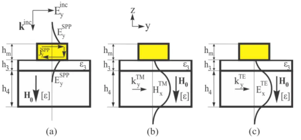
explained as follows. The Eyinc electric field component of the incident TEM wave produces on both
sides of metal elements SPP (surface plasmon-polariton) mode with the current jySPP (see Fig.1a). Due
to overlap of the Ey fields, this mode excites a waveguide TM mode with the wave vector kyTM and
with the components Ey, Hx and Ez, (see Fig.1b) in MO layer (in fact it is a hybrid plasmon polariton
mode [5]). This wave is partially excited also by the fields penetrating through slits in the metal. For simplicity, we show in Fig.1 only the wave with the wave vector +kyTM, though -kyTE is also excited
resulting in resonant effects in bismuth iron garnet (BIG) layer. Due to tensor properties of the dielectric permittivity of MO material, i.e. due to non-diagonal elements of the tensor, a TE wave with
Extremely high Faraday and Kerr rotations
and extraordinary optical transmission in
four-layer dielectric-metal strips-dielectric-Bi:YIG
planar structure
Victor Dmitriev, C. M. Santos, C. Nascimento
Brazilian Microwave and Optoelectronics Society-SBMO received 19 Sep 2017; for review 22 Sep 2017; accepted 29 Jan 2018
Brazilian Society of Electromagnetism-SBMag © 2018 SBMO/SBMag ISSN 2179-1074
the wave vector kyTE and the components Ex, Hy and Hz is also excited in MO layer (Fig.1c). As a
result, the transmitted (reflected) wave through (from) the structure acquires the component Ex of
electric field corresponding to FR (KR). The resonance nature of the effects provides a significant
enhancement of FR and KR. One of the problem in these structures is to achieve frequency coincidence of the peaks of maximum reflectance and maximum of KR or maximum of EOT and
maximum of FR. For this aim, it was suggested in [6] to fill in the air space in metal holes by a dielectric.
Fig. 1. Simplified schematic representation of fields and currents in two-layer structure with additional dielectric layer h3:
(a) excitation of SPP mode in metal by TEM incident wave with electric field Ey, (b) excitation of TM mode in MO layer by
SPP mode in metal, (c) excitation of TE mode in MO layer by TM mode due to tensor [𝛆].
FR for two-layer structures consisting of a metallic array and MO layer in the published literature is
of the order of (1º to 2º) and the transmittance at the level of (0.3 to 0.6). One solution to enhance further FR is to add an additional dielectric layer between the metal elements and MO layer. In 2D structure, this allows one to increase FR rotation to 2.58º with the transmittance of 0.46 at λ = 1099.6 nm[7]. Notice that in a 1D structure, a record value of 4.2º with transmittance of 0.3 for FR at 662 nm was reported and confirmed experimentally for low temperature (30K) regime [5]. In the infra-red region the best results in the literature for the FR and transmittance is presented in [3] where for a λ = 869 nm the FR is 3º and transmittance is 0.6.
Polar Kerr effect in two layers structures has been analyzed in sparse works [6], [8], [9]. In a 1D structure at λ = 880 nm, the angle of KR is equal to 1.1º and reflectance is smaller than 0.01 [8]. In [6] the authors investigated numerically the system where the metal has periodic square holes. In this case, the higher value of KR equal to 3.7º was obtained, but the reflectance was also lower that 0.01.
On the other hand, in [9] in the structure made of a metal layer with circular holes, a relatively high reflectance 0.2 at λ = 917 nm but with a small KR of -0.88º was reached. Like the FR, the KR can also be enhanced by inserting a dielectric between the periodically perforated metal and MO layer. In three-layer structure the authors of [7] reached the record value of KR equal to 7.5º at λ = 1099.6 nm.
Brazilian Microwave and Optoelectronics Society-SBMO received 19 Sep 2017; for review 22 Sep 2017; accepted 29 Jan 2018
Brazilian Society of Electromagnetism-SBMag © 2018 SBMO/SBMag ISSN 2179-1074
four layers (in the following we call it 4L structure). Our optimized 4L structure demonstrates FR more than two times higher as compared to that published in [3] and the KR is enhanced in more than five times. We explain the physical mechanism responsible for the improvement of the FR (KR).
II. PROBLEM DESCRIPTION
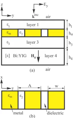
We propose insertion of an additional dielectric layer (see Fig.1) with the thickness h3 and
permittivity ε3 between the metal strips and MO layer (notice that the base structure discussed in [3]
and which is used here for comparison, has h3 = 0). Another important element which we introduce in
the structure is one more dielectric layer denoted as layer 1 with the thickness h1 (Fig.2). With these
dielectric layers, we have several additional parameters at hand to optimize the structure. In summary, our proposed structure consists of four layers. A periodic metal grating is placed on dielectric 3 with permittivity constant ε3. A dielectric with permittivity ε2 fills in the slits between the metal strips of
the grid.This three-layer set is placed on a thin layer of Bi-substituted yttrium iron garnet (Bi:YIG)
magnetized by the magnetic field H0 in -z direction. Layer 3 has the dielectric constant much lower than that of the Bi:YIG and this leads to a reduction of coupling between the metal grating and the
MO waveguide.
Fig. 2.Four-layer structure, a) side view, b) top view without layer 1.
In the numerical analysis, optical properties of the metal, which is gold (Au), are modelled by the
following dielectric function 𝜀𝑚 [2], [7], [8], [9]:
𝜀𝑚 = 𝜀∞− 𝜔𝑝 2
Brazilian Microwave and Optoelectronics Society-SBMO received 19 Sep 2017; for review 22 Sep 2017; accepted 29 Jan 2018
Brazilian Society of Electromagnetism-SBMag © 2018 SBMO/SBMag ISSN 2179-1074
where 𝜀∞ the high-frequency limit dielectric, 𝜔𝑝 the plasma frequency, ω frequency of incident wave
and γ the damping term. For the film of gold in the wavelength region of interest, the parameters of
E q . ( 1 ) have the following values: 𝜀∞ = 7.9, 𝜔𝑝= 1.3324.1016 s-1 and 𝛾 = 1.1395.1014 s-1. These
parameters correspond to the experimental data of [10].
The MO material is described by the permittivity tensor
[𝜀] = [−𝑖𝑔 𝜀𝜀𝑟 𝑖𝑔 0𝑟 0
0 0 𝜀𝑟
],
where 𝜀𝑟= 5.5 + i0.0025 and 𝑔= 0.01 - i0.0015 [2], [7], [8], [9]. The magnetic permeability of the
Bi:YIG layer, the gold and the dielectrics are considered to be equal to 1.
Several dielectrics used in optics possess the permittivity in the region of 1.9 to 5 (for
example, MgF2, SiO, SiO2, TiO2, Al2O3, etc). Thus, in the optimization process we varied the
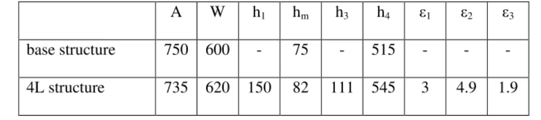
permittivity constants in this interval. The dimensions and parameters of the 4L structure are given in
Table I.
TABLE I.PARAMETERS OF BASE STRUCTURE AND 4L STRUCTURE (DIMENSIONS ARE IN NANOMETERS).
A W h1 hm h3 h4 ε1 ε2 ε3
base structure 750 600 - 75 - 515 - - -
4L structure 735 620 150 82 111 545 3 4.9 1.9
The structure is illuminated by a plane wave with normal incidence polarized in y-direction, i.e.
perpendicular to the slits of metal. The numerical analyses was fulfilled using the commercial
software COMSOL [11].
III. RESULTS AND DISCUSSION
In this section, we investigate the influence of gap h3 on FR (KR). The gap between the metallic
strip and MO layer reduces the coupling of the SPP mode of the metal and TM mode of the MO
waveguide. Consequently, the Q-factor of the resonance related to the Faraday or Kerr effect
generated in the structure can be enhanced. In the base structure where the metal strips are placed
Brazilian Microwave and Optoelectronics Society-SBMO received 19 Sep 2017; for review 22 Sep 2017; accepted 29 Jan 2018
Brazilian Society of Electromagnetism-SBMag © 2018 SBMO/SBMag ISSN 2179-1074
maximum value. As a result, the quality factor of the TM mode resonance is relatively low and the
resonance curve corresponding to FR has a low maximum. The introduction of the gap reduces the
coupling constant and, as a consequence, increases the quality factor of resonance. The higher quality
factor leads to to a higher value of the FR and KR resonance peaks.
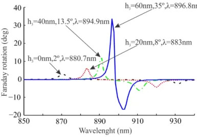
In our discussion firstly we shall consider the gap h3 filled by air and the parameters of the base
structure used in [8] are given in Table 1. Fig.3 demonstrates the h3 dependence of FR for this
modified base structure. One can see that when h3 is increased, the quality factor of the resonance and
the angle of FR increase until a certain extreme value which, is one order higher than that for the
structure withour air gap. With increasing h3 the positive resonance is gradually shifted to higher
wavelengths whereasthe negative resonance is shifted to lower wavelengths.
Fig. 3. Faraday rotation spectra in base structure for different gaps h3.
The role of dielectric layer 1 is to improve the figure of merit (FOM) due to better impedance
matching of the structure with the incident wave. The FOM is defined for the transmitted wave
as |𝜃 𝐹 |√𝑇, where 𝜃 𝐹is the angle of FR and T is the transmittance [3], [12]. Dependence of the
FOM with respect h1 is shown in Fig.4. One can see that there is an optimum value of h1
Brazilian Microwave and Optoelectronics Society-SBMO received 19 Sep 2017; for review 22 Sep 2017; accepted 29 Jan 2018
Brazilian Society of Electromagnetism-SBMag © 2018 SBMO/SBMag ISSN 2179-1074
Fig. 4. Figure of merit for 4L structure versus of h1, ε1 = 3. For every value of h1 there is a wavelength to which the figure of merit has maximum value. Thus, for example, for h1 = 150 nm (optimal value) the FOM has your maximum value for
wavelength equal to 945 nm.
The field distributions for the base structure and for 4L configuration with the parameters given in
Table 1 are shown in Fig.5a, 5b, 5c and 5d. In this case, the field distribution inside the structure 4L is
defined by the values of the geometric parameters (for example, pitch and thicknesses) as well as the
values of permittivity of the dielectrics present in the structure. Comparing Fig.5c and Fig.5d one can
see that the maximum intensity of the field Ex in the suggested structure is six times higher than in
Brazilian Microwave and Optoelectronics Society-SBMO received 19 Sep 2017; for review 22 Sep 2017; accepted 29 Jan 2018
Brazilian Society of Electromagnetism-SBMag © 2018 SBMO/SBMag ISSN 2179-1074
Fig. 5. Spatial distributions of |Hx| in (a) and |Ex| in (c) for base structure at λ = 870.7 nm. Spatial distributions of |Hx| in (b) and |Ex| in (d) for structure 4L at λ = 945 nm. Amplitudes of fields are normalized to that of incident light.
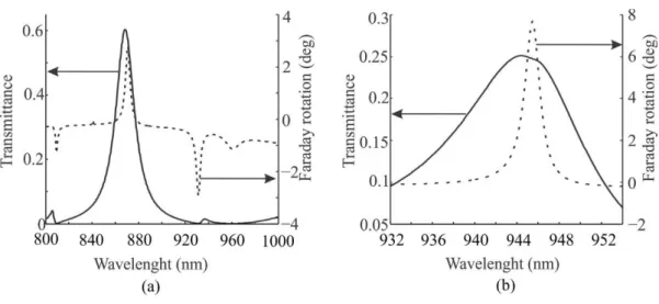
The FR and transmittance spectrum for the base structure and 4L are given in Fig.6. The base
structure possesses the FR equal to 2.75º and transmittance 0.57 at λ = 870.7 nm (see Fig.6a). Note
that the values of the FR and transmittance calculated for base structure using COMSOL are
consistent with those obtained in [8] where the authors used another numerical method. On the other
hand, the 4L structure in λ = 945 nm has FR equal to 7.8º and the transmittance equal to 0.25, Fig.6b.
These results demonstrate that in 4L structure the FR is increased more than two times in comparison
to the base structure.
Fig. 6. Transmittance and Faraday rotation spectra, (a) base structure, (b) 4L structure.
For these two configurations the FR is accompanied by EOT, however level of transmittance for
the case analyzed in [8] is better than that for our 4L structure. But, comparing the two configurations
from the point view of FOM, the 4L structure has FOM = 3.9 whereas the base structure has FOM =
2.05. Thus, the proposed structure has the FOM increased almost 2 times compared to the
configuration presented in [8].
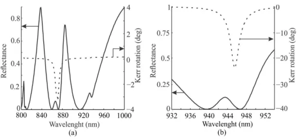
In Fig.7a we show the spectra of KR and reflectance of the base structure. At λ = 870.9 nm, it has
KR equals to -3.2º and the reflectance 0.03. In 4L configuration we succeded not only the FR
improvement but also a better value of the KR. The spectra of KR and reflectance for 4L are given in
Fig.7b. For λ = 945 nm the KR equals to -23.8º and the reflectance is 0.04. Evidently, the proposed
Brazilian Microwave and Optoelectronics Society-SBMO received 19 Sep 2017; for review 22 Sep 2017; accepted 29 Jan 2018
Brazilian Society of Electromagnetism-SBMag © 2018 SBMO/SBMag ISSN 2179-1074
value -23.8º of KR is a record for the known structures with metallic periodic elements and MO
material.
Fig. 7. Spectra of reflectance and KR rotation, (a) base structure and (b) 4L structure.
In addition, we calculated the FOM to the wavelength with higher KR. In the case of wave
reflection, the FOM can be described in terms of the Kerr rotation 𝜃 𝐾 and reflectance R, i.e |𝜃 𝐾 |√𝑅.
For the 4L structure, the FOM is 8.6 times higher than that for base structure.
IV. CONCLUSION
We have shown theoretically that it is possible to reach simultaneously high value Faraday rotation
with EOT simultaneously in the new four-layer planar structure. It exhibits extremely high Kerr
rotation as compared with the other reported structures. The increase of the Faraday (Kerr) rotation is
due to the presence of the dielectric between the metal strips and MO material that reduces the
coupling constant of the system and consequently increases the Q-factor of the resonance. We believe
that the suggested structure can find application in magnetic field and current sensors, in magnetic
microscopy, optical modulators, data storage device and etc. Enhanced resonant electromagnetic field
in the MO layer can promote nonlinear MO effects.
ACKNOWLEDGMENT
This work was supported by Brazilian agencies CAPES and CNPq.
Brazilian Microwave and Optoelectronics Society-SBMO received 19 Sep 2017; for review 22 Sep 2017; accepted 29 Jan 2018
Brazilian Society of Electromagnetism-SBMag © 2018 SBMO/SBMag ISSN 2179-1074
[1] F.J. Garcia-Vidal, L. Martin-Moreno, T.W. Ebbesen, and L. Kuipers, Light passing through subwavelength apertures,
Rev. Mod. Phys., 82 (2010), 729-787.
[2] V. L. Belotelov, L.L. Doskolovich, and A.K. Zvezdin, Extraordinary magneto-optical effects and transmission through
metal-dielectric plasmonic systems, Phys. Rev. Lett., vol. 98, (2007), pp. 1-4.
[3] H. Xu and B.S. Ham, Investigation of extraordinary optical transmission and Faraday effect in one-dimensional
metallic-magnetic gratings, Opt. express, vol. 16, (2008), pp. 21375-21382.
[4] J. Y. Chin, T. Steinle, T. Wehlus, D. Dregely, T. Weiss, V. I. Belotelov, B. Stritzker and H. Giessen, Nonreciprocal
plasmonics enables giant enhancement of thin-film Faraday rotation, Nat. Commun., vol. 4, (2013), pp. 1-6.
[5] D. Floess, J. Y. Chin, A. Kawatani, D. Dregely, H. Habermeier, T. Weiss, and H. Giessen, Tunable and switchable
polarization rotation with non-reciprocal plasmonic thin films at designated wavelengths, Light Sci Appl, vol. 4, (2015), pp.
1-7.
[6] D. Li, C. Lei, L. Chen, Z. Tang, S. Zhang, S. Tang, and Y. Du, Waveguide plasmon resonance induced enhancement of
the magneto-optics in a Ag/Bi: YIG bilayer structure, JOSA B, vol. 32, (2015), pp. 2003-2008.
[7] V. Dmitriev, F. Paixão, and M. Kawakatsu, Enhancement of Faraday and Kerr rotations in three-layer heterostructure
with extraordinary optical transmission effec, Opt. Lett., vol. 38, (2013), pp. 1052-1054.
[8] V. L. Belotelov, L.L. Doskolovich, V.A Kotov, E.A. Bezus, D.A. Bykov, and A.K Zvezdin, Faraday rotation effect
enhancement in metal-dielectric plasmonic systems, Proc. Of SPIE, vol. 6581, (2007), pp. 1-8.
[9] D. Li, L. Chen, C. Lei, J.L. Menendez, C. Mallada, Z. Tang, S. Tang, and Y. Du. Plasmon-enhanced magneto-optical
activity in nanostructure with circle annular arrays, JOSA B, vol. 33, (2016), pp. 922-927.
[10] D. Palik, Handbook of optical constants of solids, Edward Academic Press Inc., Orlando, FL, 1985.
[11] https://www.comsol.com
[12] A. K. Zvezdin and and V. A. Kotov, Modern Magnetooptics and Magnetooptical Materials, Taylor & Francis, New