Abstract
This paper dealt with free vibration analysis of thick double curved composite sandwich panels with simply supported or fully clamped boundary conditions based on a new improved higher order sandwich panel theory. The formulation used the first order shear deformation theory for composite face sheets and polynomial description for the displacement field in the core layer which was based on the displacement field of Frostig's second model. The fully dynamic effects of the core layer and face sheets were also considered in this study. Using the Hamilton's principle, the gov-erning equations were derived. Moreover, effects of some im-portant parameters like that of boundary conditions, thickness ratio of the core to panel, radii curvatures and composite lay-up sequences were investigated on free vibration response of the pan-el. The results were validated by those published in the literature and with the FE results obtained by ABAQUS software. It was shown that thicker panels with a thicker core provided greater resistance to resonant vibrations. Also, effect of increasing the core thickness in general was significant decreased fundamental natural frequency values.
Keywords
Free vibration, Double curved sandwich panel, Boundary conditions, Improved higher order sandwich panel theory.
Improved high order free vibration analysis of thick double curved
sandwich panels with transversely flexible cores
1 INTRODUCTION
Structural efficiency is an important attribute for aircraft structures. A higher order theory ap-proach, used by Kant and Patil (1991), replaced sandwich structure with an equivalent higher order shear deformable structure, which lacked the ability to determine local buckling modes and imper-fection effects on the overall behavior. Using the three-dimensional elasticity equations, Bhimaraddi (1993) studied the static response of orthotropic doubly curved shallow shells. He assumed that the ratio of the shell thickness to its middle surface radius is negligible as compared to unity. The
high-K. Malekzadeh Fard a *
M. Livani a
Faramarz Ashenai Ghasemi b
a Department of Structural Analysis
and Simulation, Space Research Insti-tute, Malek Ashtar University of Tech-nology, Tehran-Karaj Highway, Post box: 13445-768, Tehran, Iran [email protected]
b Department of Mechanical
Engineer-ing, Shahid Rajaee Teacher Training University (SRTTU), Lavizan, Postal Code 16788-15811,Tehran, Iran. [email protected]
*Author email: [email protected]
Latin American Journal of Solids and Structures 11 (2014) 2284-2307
er order sandwich panel theory was developed by Frostig et al. (1994, 2004), who considered two
types of computational models in order to express governing equations of the core layer. The second model assumed a polynomial description of the displacement fields in the core that was based on displacement fields of the first model. Their theory did not impose any restrictions on distribution of the deformation through thickness of the core. Singh (1999) studied free vibration of the open deep sandwich shells made of thin layers and a moderately thick core. Rayleigh–Ritz method was also used to obtain natural frequencies. The improved higher order sandwich plate theory (IHSAPT), applying the first-order shear deformation theory for the face sheets, was introduced by Malekzadeh et al. (2005, 2006).
NOTATIONS
, ,
t c b
dV dV dV Volume element of the top face sheet, the core and the bottom face sheet,
respec-tively
( , , )
i n
I i =t b c The moments of inertia of the top and bottom face sheets and the core c
z
M Normal bending moments per unit length of the edge of the core
, , ,
i i i i
xy yx xx yy
M M M M Bending and shear moments per unit length of the edge (i=t,b)
* *
, , ,
, , ,
c c c c
nxx nxy nyy nyx
c c c c
nxz nyz nxz nyz
M M M M M M M M
Shear and bending moments per unit length of the edge of the core, (n=1,2,3)
, ,
i i i
xxj yyj xyj
N N N The in-plane external loads in the longitudinal and transverse direction,
respec-tively (i = t, b), (j=1,2)
, , ,
i i i i
xy yx xx yy
N N N N In-plane and shear forces per unit length of the edge (i=t,b)
* *
, , ,
c c c c
xz yz xz yz
N N N N Shear forces per unit length of the edge of the core
, ,
i i i
xxj yyj xyj
N N N In plane resultant forces due to pre stresses (j=t,b)
ij
Q The reduced stiffnesses referred to the principal material coordinates
ij
Q Transformed reduced stiffnesses
,
ix iy
R R Curvature radii of the top face sheet, bottom face sheet and core in x-z and y-z
planes (i=t,b,c) , ,
k k k
u v w Unknowns of the in-plane displacements of the core (k=0,1,2,3)
, ,
c c c
u v w Displacement components of the core
u0i,v0i,w0i Displacement components of the face sheets, (i = t, b)
uc,
v
c,w
c Acceleration components of the core
u0j,v0j,w0j Acceleration components of the face sheets, (j= t, b)
zt , zb ,zc Normal coordinates in the mid-plane of the top and the bottom face sheets and
Latin American Journal of Solids and Structures 11 (2014) 2284-2307
GREEK LETTERS
t,b,c Material densities of the face sheets and the core
iij Normal stress in the face sheets, (i=x,y), j=(t,b)
iic Normal stress in the core, (i=x,y,z)
xyj,xzj,yzj Shear stress in the face sheets, j=(t,b)
xyc,xzc,yzc Shear stresses in the core
0ixx,0ixy,i0yy,0ixz,0ixz The mid-plane strain components, (i=t,b)
zzc,xxc,yyc Normal strains components of the core layer
xzc,yzc,xyc Shear strains components of the core layer
xi,yi Rotation of the normal section of midsurface of the top face sheet and bottom face
sheet along x and y, respectively(i=t,b)
Zenkour (2005a, b) presented a comprehensive bending, buckling and free vibration analysis of simply supported functionally graded (FG) ceramic–metal sandwich plates. The sandwich plate face sheets were assumed to be isotropic material. Two-constituent material distribution through thick-ness was assumed to vary according to a power law distribution.Garg et al. (2006) investigated free
vibration analysis of simply supported composite and sandwich doubly curved shells. Their formula-tion included Sander's theory based on equivalent single layer approach. Free vibraformula-tion of FG ma-terial sandwich rectangular plates with simply supported and clamped edges was studied by Li et al. (2008). The governing equations based on the three-dimensional linear theory of elasticity were
derived and also they considered two common types of FG sandwich plates, namely sandwich plate with FG face sheets and homogeneous core and sandwich plate with homogeneous face sheets and FG core.
Experimental and analytical investigations of bending and free vibration response of layered FG beams were carried out by Kapuria et al. (2008), who demonstrated capability of the zigzag theory
in modeling mechanics of such beams. Rahmani et al. (2009) studied free vibration analysis of open
single curved composite sandwich panel with a flexible core using a higher order sandwich panel theory. Their formulation used classical shell theory for the face sheets and an elasticity theory for the core layer. Cetkovic and Vuksanovic (2009) investigated global and local responses of laminated and sandwich structures using Reddy's theory, finite element solution and based on equivalent sin-gle layer approach. Biglari and Jafari (2010a) presented a simple three layer theory in order to study vibration and static analysis of open single curved sandwich structures. In their model, they used Donell's theory for the face sheets and considered inconsistent linear stress variation in the core layer. They (2010b) also studied the free vibrations of doubly curved sandwich shell with flexi-ble core based on a refined general-purpose sandwich panel theory. In their theory, the in-plane stresses of the core were neglected.
Free vibration analysis of thick orthotropic plates was performed by Ghugal et al. (2011) using a
Latin American Journal of Solids and Structures 11 (2014) 2284-2307
and bottom surfaces of the plates were satisfied. Rahmani et al. (2012) studied the free vibration
and buckling analyses of circular cylindrical composite sandwich shells subjected to external loads based on the Love–Kirchhoff assumptions for the face sheets. In their theory, the in-plane stresses of the core and the out of stresses of the face sheets were neglected. Mochida et al. (2012) studied free
vibration response of doubly curved shallow shells using approximate Galerkin method. Classical theory of elasticity and von-Karman’s non-linear deformation theory were used by Rafieipour et al. (2013) to investigate free vibration analyses of laminated composite plates.
Using developed four-node quadrilateral element and the zigzag theory, Yasin and Kapuria (2013) studied the static and free vibration analysis of singly- and doubly-curved composite and sandwich shallow shells. In their theory, the transverse normal stresses were neglected. Ghavanloo and Fazelzadeh (2013) examined free vibration analysis of simply supported doubly curved shallow shells. Their formulation was based on Novozhilov's linear shallow shell theory. Using Donell’s non-linear shallow shell theory and Kirchhoff’s hypothesis, Awrejcewicz et al. (2013) studied free
vibra-tion analysis of doubly curved orthotropic shallow shells. Viola et al. (2013) used a 2D higher order
shear deformation theory with nine parameters in order to analyze free vibration analysis of the thick laminated doubly curved shells and panels. Their main assumptions were based on small de-flections and negligible normal stress and strain. A high-order model for the analysis of circular cylindrical composite sandwich shells subjected to low-velocity impact loads was presented by Kha-lili et al. (2014). In their theory, the impact behavior of the cylindrical composite sandwich shells
was described by a high-order sandwich shell theory. Malekzadeh et al. (2014) applied the
first-order shear deformation theory to study effects of some geometrical, physical and material parame-ters on response of the composite plates embedded with shape memory alloy (SMA) wires.
This study investigated free vibration analysis of double curved thick composite sandwich panels using a new improved higher order double curved sandwich panel theory and the second computa-tional model of Frostig (2004). In this work, analytical solution of the displacement field of the core was presented in terms of the polynomials with unknown coefficients according to the second com-putational model of Frostig (2004). Furthermore, the formulation included accurate stress-resultant equations for composite sandwich structures, in which the terms (1+zc /Rxc)and (1+zc /Ryc)
were imported in equations and exactly integrated. These coefficients could be very important in the structural analysis of thick double curved composite sandwich structures. Simply supported and fully clamped boundary conditions were considered. In order to assure accuracy of the present for-mulations, convergence of the results was examined in details.
2 THEORETICAL FORMULATION
2.1 Basic Assumptions
Latin American Journal of Solids and Structures 11 (2014) 2284-2307
also shown in Figure 1 where t and b refer to the top and bottom face sheets of the panel, respec-tively. Curvature radii of the top face sheet, bottom face sheet and core in x-z and y-z planes are
, ,
tx bx cx
R R R andRty, , ,Rby Rcy respectively. The assumptions used in the present analysis were
based on small deformations of linearly elastic materials.
Figure 1: A double curved sandwich panel with laminated face sheets and orthogonal curvilinear coordinates.
2.2 Mathematical Formulation
Mathematical formulation consists of deriving the governing field equations of motion along appro-priate boundary conditions of the face sheets and core. They are derived using the Hamilton's prin-ciple (Frostig 2004).
Using the first shear deformation theory, displacements u, v and w of the face sheets along the x, y (longitudinal) and z (thickness) axes are expressed through the following relations (Reddy 2003):
0
0
0
( , , , ) ( , , ) ( , , )
( , , , ) ( , , ) ( , , ) ; ( = , ) ( , , , ) ( , , )
i i
i i
i
i i x
i i y
i
u x z y t u x y t z x y t
v x z y t v x y t z x y t i t b
w x z y t w x y t
y y
= +
= +
=
(1)
whereziis vertical coordinate of the each face sheet (i = t, b), measured upward from the mid-plane of each face sheet. Kinematic equations of the face sheets are as follows:
(
)
0 0 0
0 0
, 0, 2 ,
2 , 2 ; ,
i i i i i i i i i i i
xx xx i xx yy yy i yy zz xy xy xy i xy
i i i i i i
xz xz xz yz yz yz
z z z
i t b
e e k e e k e g e e k
g e e g e e
= + = + = = = +
Latin American Journal of Solids and Structures 11 (2014) 2284-2307
where:
0 0 0 0
0 0
0 0 0 0 0 0
0 0 0
, ,
, ,
, ,
i i i i
i i
xx yy
xi yi
i i i i i i
i i i i i
xy xz x yz y
xi yi
i i
i i
y y
i x i i x
xx yy xy
u w v w
x R y R
v u w u w v
x y x R y R
x y x y
(3)
For the thick core layer, displacement fields are based on the second Frostig's model (2004) as fol-lows:
(
)
(
)
(
)
(
)
(
)
(
)
(
)
(
)
(
)
(
)
(
)
(
)
(
)
(
)
2 3
0 1 2 3
2 3
0 1 2 3
2
0 1 2
, , , (1 ) , , , , , , , , ,
, , , (1 ) , , , , , , , , ,
, , , , , , , , , .
c c c c
c c c c
xc
c c c c
c c c c
yc
c c c
c c c
z
u x y z t u x y t z u x y t z u x y t z u x y t
R z
v x y z t v x y t z v x y t z v x y t z v x y t
R
w x y z t w x y t z w x y t z w x y t
= + + + +
= + + + +
= + +
(4)
Based on small deformations, kinematic relations of the core layer are as follows:
1
(1 )
1
(1 )
1 1
2
(1 ) (1 )
1 2
(1 )
1 2
(1 )
c
c c xx
xc xc
c
c c yy
yc yc
c c
c c
xy xy
xc yc
c c
c c c
xz xz
xc xc
c c
c c c
yz yz
yc yc
u w z R x R
v w z R y R
v u
z R x z R y
w u u
z R x R z
w v v
z R y R z
(5)
Assuming perfect bonding between the top and bottom face sheet–core interfaces, compatibility conditions are as shown below:
0 0 0
1 1
2 1 ;
2 1
1 2
0 ;
2
k
i i
c ci i x
c ct k
i i
c ci i y
c
i cb
c ci
u z z u h
h For i t k z
v z z v h
h For i b k z
w z z w
(6)
Latin American Journal of Solids and Structures 11 (2014) 2284-2307
0
0 0 1
0 0 0
2 2 3 3
0
0 0 1
0 0 0
2 2 3 3
0 0 0 0
1 2
4
4( ) 2( ) 4
2( ) 4
, ,
4
4( ) 2( ) 4
2( ) 4
, ,
( ) 2( )
,
c
t b t b c c
t x b x c
t b t b c
c t x b x c xc
c c
c
t b t b c c
t y b y c
t b t b c
t y b y yc
c c
c c
t b t b
c c
c
h u
u u h h h u
u u h h u R
u u
h h
h v
v v h h h v
v v h h v R
v v
h h
w w w w
w w
h
y y
y y
y y
y y
- - + -
-+ - +
-= =
- - + -
-+ - +
-= =
- +
= = 0
2
4 .
c c
w
h
-(7)
It can be seen in Equation (7) that the number of unknowns in the core layer is reduced to five. These unknowns areu u v v0c, 1c, 0c, 1cand
0
c
w . Therefore, generally, all unknowns for a double curved
composite sandwich panel are fifteen as follows:
{
u v w0t, ,t0 0t,y yxt, yt, , ,u v w0b b0 0b,y yxb, by,u u v v wc0, c1, , ,c0 1c 0c}
The governing equations are derived using the Hamilton's principle which requires that:
0 0
[ ] 0
t t
Ldt K U dt
(8)wheredK anddUdenote variation of kinetic energy and strain energy, respectively. Also, t is time
duration between timest1andt2, andddenotes variation operator.
The first variation of kinetic energy (assuming homogeneous conditions for displacement and velocity with respect to time coordinate) can be written as follows:
(9)
where
(1 c )(1 c ) , , ( , )
c c c i i i
xc yc
z z
dA dx dy dA dx dy i t b
R R
= + + = =
and ( ۟◌ ۟◌ ۟◌ ۟◌ ۟◌ ۟◌ ) denotes the second derivative in time. The first variation of internal potential en-ergy of the sandwich panel is as follows:
,
i
c
i i i i i i t i i i
xx xx yy yy xy xy xz xz yz yz i i t b V
c c c c c c c c c c c c
xx xx yy yy zz zz xy xy xz xz yz yz c V
U dV
dV
Latin American Journal of Solids and Structures 11 (2014) 2284-2307
where:
(1 c )(1 c ) , ; ( , )
c c c c c c i i i i i i
xc yc
z z
dV dA dz dx dy dz dV dAdz dx dy dz i t b
R R
= = + + = = =
Using the Hamilton's principle (Equations (8)-(10)) and the kinematic relations (Equations (1)-(7)), equations of motion are obtained as follows:
Qxzt
Rtx 2 hc2M2xx,x
c 4
hc3M3xx,x c 2
hc2M2yx,y c 4
hc3M3yx,y c 2
Rtxhc2M2xz c 4
Rtxhc3M3xz c
4 hc2M1xz
*c12
hc3M2xz
*c
I0t 4I4
c
hc4
16I5c hc5
16I6c hc6
u0t 4I4
c
hc4
16I6c hc6
u0b
2 hc2(I2
c I3
c
Rxc) 4 hc3(I3
c I4
c
Rxc) 8I4c
hc4
8I5c
hc4
Rxc 16I5c
hc5
16I6c
Rxchc5
u0c
2I3c
hc2
4I4
c
hc3
8I5c
hc4
16I6c
hc5
u1c
I1t2htI4
c
hc4
8htI5c
hc5
8htI6c
hc6
xt 2hbI4
c
hc4
8hbI6c
hc6
xb
(11)
Qxzb Rbx
2 hc2M2xx,x
c 4
hc3M3xx,x c 2
hc2M2yx,y c 4
hc3M3yx,y c 2
Rbxhc2M2xz c 4
Rbxhc3M3xz c
4 hc2M1xz
*c12
hc3M2xz
*c 4I4
c
hc4
16I6c
hc6
u0t
I0b4I4
c
hc4
16I5c
hc5
16I6c
hc6
u0b
2 hc2(I2
c I3
c
Rxc) 4 hc3(I3
c I4
c
Rxc) 8I4c
hc4
8I5c
hc4
Rxc 16I5c
hc5
16I6c
Rxchc5
u0c
2I3c
hc2
4I4
c
hc3
8I5c
hc4
16I6c
hc5
u1c 2htI4
c
hc4
8htI6c
hc6
xt
I1b2hbI4
c
hc4
8hbI5c
hc5
8hbI6c
hc6
xb
(12)
Qyzt Rty
2 hc2M2yy,y
c 4
hc3M3yy,y c 2
hc2M2xy,x c 4
hc3M3xy,x c 2
Rcyhc2M2yz c 4
Rcyhc3M3yz c 4
hc2M1yz
*c
12 hc3M2yz
*c
I0t4I4
c
hc4
16I5c
hc5
16I6c
hc6
v0t 4I4
c
hc4
16I6c
hc6
v0b
2 hc2(I2
c I3
c
Ryc) 4 hc3(I3
c I4
c
Ryc) 8I4c
hc4
8I5c
hc4
Ryc 16I5c
hc5
16I6c
Rychc5
v0
c
2I3c
hc2
4I4
c
hc3
8I5c
hc4
16I6c
hc5
v1c
I1t2htI4
c
hc4
8htI5c
hc5
8htI6c
hc6
y
t 2hbI4
c
hc4
8hbI6c
hc6
y b
Latin American Journal of Solids and Structures 11 (2014) 2284-2307
Qyzb Rby
2 hc2M2yy,y
c 4
hc3M3yy,y c 2
hc2M2xy,x c 4
hc3M3xy,x c 2
Rcyhc2M2yz c 4
Rcyhc3M3yz c
4 hc2M1yz
*c 12
hc3M2yz
*c 4I4
c
hc4
16I6c hc6
v0t
I0b4I4
c
hc4
16I5c hc5
16I6c hc6
v0b
2 hc2(I2
c I3
c
Ryc) 4 hc3(I3
c I4
c
Ryc) 8I4c
hc4
8I5c
hc4
Ryc 16I5c
hc5
16I6c
Rychc5
v0
c
2I3c
hc2
4I4
c
hc3
8I5c
hc4
16I6c
hc5
v1c 2htI4
c
hc4
8htI6c
hc6
y t
I1b2hbI4
c
hc4
8hbI5c
hc5
8hbI6c
hc6
y b
(14)
Qxzt,x
Qyzt ,y(Nxx t
Rtx Nyyt
Rty ) Rzc
hc 1 Rcxhc M1xx
c 4
hc2Mz c 2
Rcxhc2M2xx c 1
RcyhcM1yy c
2 Rcyhc2M2yy
c 1
hcM1xz,x c 2
hc2M2xz,x c 1
hcM1yz,y c 2
hc2M2yz,y c
I0tI2
c
hc2
4I3c
hc3
4I4c
hc4
w0t I2
c
hc2
4I4c
hc4
w0b I1
c
hc 2I2c
hc2
4I3c
hc3
8I4c
hc4
w0c
(15)
Qxzb,xQyzb,y(Nxx b
Rbx Nyyb
Rby ) Rzc
hc 1 RcxhcM1xx
c 4 hc2Mz
c 2 Rcxhc2M2xx
c 1 RcyhcM1yy
c
2 Rcyhc2M2yy
c 1 hcM1xz,x
c 2 hc2M2xz,x
c 1 hcM1yz,y
c 2 hc2M2yz,y
c I2
c
hc2
4I4c hc4
w0t
I0bI2
c
hc2
4I3c hc3
4I4c hc4
w0b I1
c
hc 2I2c
hc2
4I3c hc3
8I4c hc4
w0c
(16)
Mxxt,x Mxyt ,y
Qxzt ht hc2M2xx,x
c 2ht hc3 M3xx,x
c ht hc2M2yx,y
c 2ht hc3 M3yx,y
c ht Rcxhc2M2xz
c
2ht Rcxhc2M3xz
c 2ht hc2 M1xz
*c 6ht hc3 M2xz
*c
I1t 2htI4
c
hc4
8htI5
c
hc5
8htI6c hc6
u0t
(2htI4
c
hc4
8htI6c hc6 )u0
b
ht hc2(I2
c I3
c
Rxc) 2ht
hc3 (I3
c I4
c
Rxc) 4htI4c
hc4
4htI5c Rxchc4
8htI5c hc5
8htI6c Rxchc5
u0c
htI3
c
hc2
2htI4c hc3
4htI5c hc4
8htI6c hc5
u1c hthbI4
c
hc4
4hthbI6c hc6
xb
I2tht
2
I4c hc4
4ht2
I5c hc5
4ht2
I6c hc6
xt
Latin American Journal of Solids and Structures 11 (2014) 2284-2307
Mxxb,x Mxyb,y
Qxzb hb hc2M2xx,x
c 2hb hc3 M3xx,x
c hb hc2M2yx,y
c 2hb hc3 M3yx,y
c hb Rcxhc2M2xz
c
2hb Rcxhc2M3xz
c 2hb hc2 M1xz
*c 6hb hc3 M2xz
*c 2htI4
c
hc4
8htI6
c
hc6
u0t(
I1b2hbI4
c
hc4
8hbI5c hc5
8hbI6c hc6 )u0
b
hb hc2(I2
c I3
c
Rxc) 2hb
hc3 (I3
c I4
c
Rxc) 4hbI4c
hc4
4hbI5c Rxchc4
8hbI5c hc5
8hbI6c Rxchc5
u0c
hbI3c hc2
2hbI4c hc3
4hbI5c hc4
8hbI6c hc5
u1c hthbI4
c
hc4
4hthbI6c hc6
xt I2bhb
2
I4c hc4
4hb2
I5c hc5
4hb2
I6c hc6
xb
(18)
Mxyt,xMyyt ,yQyzt ht hc2M2yy,y
c 2ht hc3 M3yy,y
c ht hc2M2xy,x
c 2ht hc3 M3xy,x
c ht Rcxhc2M2yz
c
2ht Rcxhc2M3yz
c 2ht hc2 M1yz
*c 6ht hc3 M2yz
*c
I1t2htI4
c
hc4
8htI5
c
hc5
8htI6c hc6
v0t 2htI4
c
hc4
8htI6c hc6
v0b
ht hc2(I2
c I3
c
Ryc) 2ht
hc3 (I3
c I4
c
Ryc) 4htI4c
hc4
4htI5c Rychc4
8htI5c hc5
8htI6c Rychc5
v0
c
htI3
c
hc2
2htI4c hc3
4htI5c hc4
8htI6c hc5
v1c
I2tht
2
I4c hc4
4ht2
I5c hc5
4ht2
I6c hc6
ty hthbI4
c
hc4
4hthbI6c hc6
by
(19)
Mxyb,x
Myyb,y
Qyzb hb
hc2M2yy,y c 2hb
hc3 M3yy,y c hb
hc2M2xy,x c 2hb
hc3 M3xy,x c hb
Rcyhc2M2yz c 2hb
Rcyhc2M3yz c
2hb
hc2 M1yz
*c 6hb
hc3 M2yz
*c 2htI4
c
hc4
8htI6
c
hc6
v0t I1b2hbI4
c
hc4
8hbI5c
hc5
8hbI6c
hc6
v0b
hb hc2(I2
c I3
c
Ryc) 2hb
hc3 (I3
c I4
c
Ryc) 4hbI4c
hc4
4hbI5c
Rychc4
8hbI5c
hc5
8hbI6c
Rychc5
v0
c
hbI3c hc2
2hbI4c hc3
4hbI5c hc4
8hbI6c hc5
v1c hthbI4
c
hc4
4hthbI6c hc6
y t
I2bhb
2
I4c hc4
4hb2
I5c hc5
4hb2
I6c hc6
y b
Latin American Journal of Solids and Structures 11 (2014) 2284-2307
(Nxxc,x
Nyxc,y 4
hc2M2xx,x c 4
Rcxhc2M3xx,x c 1
Rcx M1yx,y c 4
hc2M2yx,y c 4
Rcxhc2M3yx,y c 1
Rcx Nxz
c
4 Rcxhc2M2xz
c 4
Rcx2
hc2M3xz c 8
hc2M1xz
*c 12
Rcxhc2M2xz
*c 1
Rcx Nxz
*c
) I0c I2
c
Rxc2
2I1c
Rxc 8 hc2(I2
c I3
c
Rxc)
8 hc2
Rxc(I3
c I4
c
Rxc) 16I4c
hc4
32I5c
Rxchc4
16I6c
Rxc2
hc4
u0c
I1c I2
c
Rxc 8I3c
hc2
8I4c
hc2
Rxc 16I5c
hc4
16I6c
Rxchc4
u1c
2 hc2(I2
c I3
c
Rxc) 4 hc3(I3
c I4
c
Rxc) 8I4c
hc4 16I5c
hc5 8I5c Rxchc4
16I6c Rxchc5
u0b( 2
hc2(I2
c I3
c
Rxc) 4 hc3(I3
c I4
c
Rxc)
8I4
c
hc4
16I5c hc5
8I5c Rxchc4
16I6c Rxchc5)u0
t hb
hc2(I2
c I3
c
Rxc) 2hb
hc3 (I3
c I4
c
Rxc) 4hbI4c
hc4
8hbI5c hc5
4hchbI5c Rxchc5
8hchbI6c
Rxchc6
xb ht
hc2(I2
c I3
c
Rxc) 2ht
hc3 (I3
c I4
c
Rxc) 4htI4c
hc4
8htI5c
hc5
4hchtI5
c
Rxchc5
8hchtI6c
Rxchc6
xt
(21)
M1cxx,x
Nxz*c 4
hc2M3xx,x
c
M1cyx,y 4
hc2M3yx,y
c 1
RcxM1xz c 4
Rcxhc2M3xz
c 12
hc2M2xz
*c
2I3c
hc2
4I4c
hc3
8I5c
hc4
16I6c
hc5
u0t 2I3
c
hc2
4I4c
hc3
8I5c
hc4
16I6c
hc5
u0b
I1c I2
c
Rxc 8I3c
hc2
8I4c
hc2
Rxc 16I5c
hc4
16I6c
Rxchc4
u0c
I2c8I4
c
hc2
16I6c
hc4
u1c
htI3
c
hc2
2htI4c
hc3
4htI5c
hc4
8htI6c
hc5
xt hbI3
c
hc2
2hbI4
c
hc3
4hbI5c
hc4
8hbI6c
hc5
xb
Latin American Journal of Solids and Structures 11 (2014) 2284-2307
In Equations (11)-(25), c
(
0, 1, , 6)
n n
I = ¼ are moments of inertia for the core layer, as indicated
below:
2
2
(1 )(1 ) ; 0,1,..., 6
c
c
h
c n c c
n c c c
h xc yc
z z
I z dz n
R R
(26)Nyyc,yNxyc,x 4 hc2M2yy,y
c 4
Rcyhc2M3yy,y c 1
Rcy M1xy,x
c 4
hc2M2xy,x c 4
Rcyhc2M3xy,x c
1 Rcy Nyz
c 4
Rcyhc2M2yz c 4
Rcy2
hc2M3yz c 8
hc2M1yz
*c 12
Rcyhc2M2yz
*c 1
Rcy Nyz
*c
2
hc2(I2
c I3
c
Ryc)
4
hc3(I3
c I4
c
Ryc)
8I4c
hc4
16I5c
hc5
8I5c
Rychc4
16I6c
Rychc5
v0
t
2
hc2(I2
c I3
c
Ryc)
4
hc3(I3
c I4
c
Ryc)
8I4c
hc4
16I5c
hc5
8I5c
Rychc4
16I6c
Rychc5
v0
b
I0c I2
c
Ryc2
2I1c
Ryc
8
hc2(I2
c I3
c
Ryc)
h 8
c
2
Ryc(I3
c I4
c
Ryc)
16I4c
hc4
32I5c
Rychc4
16I6c
Ryc2
hc4
v0
c
I1c I2
c
Ryc
8I3c
hc2
8I4c
hc2
Ryc
16I5c
hc4
16I6c
Rychc4
v1
c
ht
hc2(I2
c I3
c
Ryc)
2ht
hc3 (I3
c I4
c
Ryc)
4htI4c
hc4
8htI5c
hc5
4hchtI5
c
Rychc5
8hchtI6c
Rychc6
x
t
hb hc2(I2
c I3
c
Ryc)
2hb
hc3 (I3
c I4
c
Ryc)
4hbI4c
hc4
8hbI5c
hc5
4hchbI5c
Rychc5
8hchbI6
c
Rcyhc6
y
b
(23)
M1cyy,y
Nyz*c 4
hc2M3yy,y c
M1cxy,x 4
hc2M3xy,x c 1
Rcy M1yz c 4
Rcyhc2M3yz c
12
hc2M2yz
*c 2I3
c
hc2
4I4c
hc3
8I5c
hc4
16I6c
hc5
v0t 2I3
c
hc2
4I4c
hc3
8I5c
hc4
16I6c
hc5
v0b
I1c I2
c
Ryc
8I3c
hc2
8I4c
hc2
Ryc
16I5c
hc4
16I6c
Rychc4
v0
c
I2c8I4
c
hc2
16I6c
hc4
v1c
htI3
c
hc2
2htI4c
hc3
4htI5c
hc4
8htI6c
hc5
ty hbI3
c
hc2
2hbI4
c
hc3
4hbI5c
hc4
8hbI6c
hc5
yb
(24)
Nxzc,x
Nyzc,y 8 hc2Mz
c 1 Rxc Nxx
c 4 Rxchc2M2xx
c 1 Ryc Nyy
c 4 Rychc2M2yy
c 4 hc2M2xz,x
c
4 hc2M2yz,y
c I1
c
hc 2I2c
hc2
4I3c hc3
8I4c hc4
w0t I1
c
hc 2I2c
hc2
4I3c hc3
8I4c hc4
w0b
I0c8I2
c
hc2
16I4c hc4
w0c


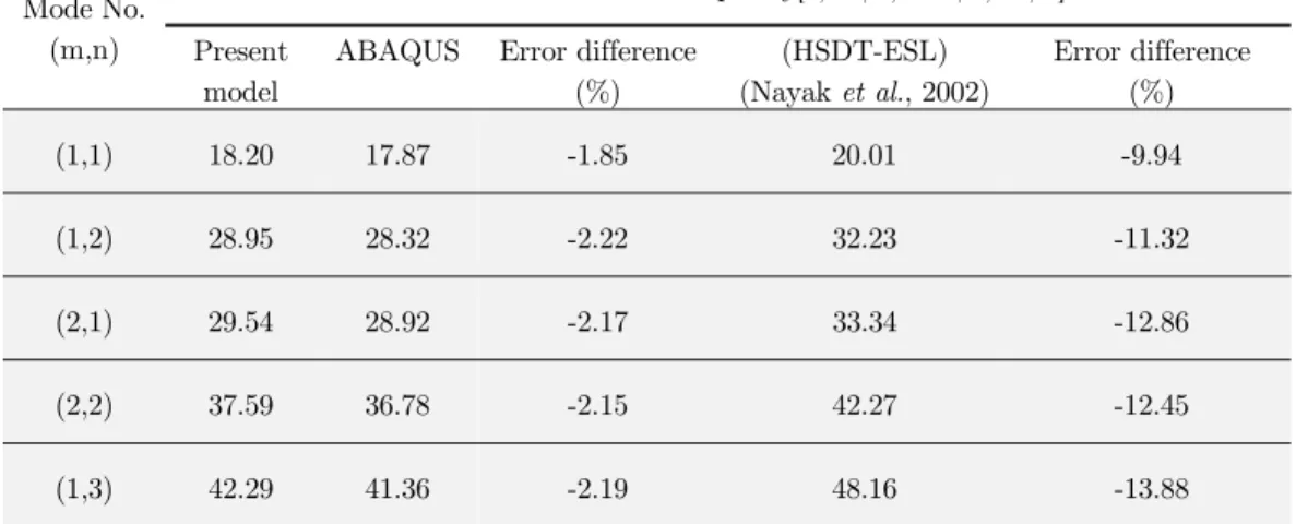
![Table 3: Comparing dimensionless natural frequencies of a flat composite sandwich panel [45/-45/45/core/45/-45/45]](https://thumb-eu.123doks.com/thumbv2/123dok_br/18885070.423636/16.808.135.720.275.416/table-comparing-dimensionless-natural-frequencies-composite-sandwich-panel.webp)