Abstract
The last years, ground vibrations have become an important study field due to the increase of the transports needs for society and its amount of running trains associated. The vibrations caused by trains are an important comfort and environmentally problem affecting more people every day. This is an experimental paper which compare the vibrational response of the different sleepers disposed on the line. The section presents different sleepers due to a recent actuation to solve instability phenomena . The vibrations measured on site allow to know better how influent is the different materials on the vibrational behavior of the track
.
Keywords
Sleeper vibrations, ballasted track, railway.
Comparison of the effect of different sleeper typologies
and track layout on railway vibrations
1 INTRODUCTION
The higher velocities, the amount of trains and the proximity to populated areas, make necessary to know better the vibrations generated by the passing of railway vehicles in order to attenuate it. This phenomenon can produce comfort problems to the train passengers, acoustic problems, and even could affect to the neighboring structures and inhabitants. For these reasons is neces-sary to know the vibrations produced by the pass of trains and attenuate it.
The main purpose of this experimental paper is to determine how different is the vibrational re-sponse with both concrete and wood sleepers and their different geometry, disposed at the section.
J. Real a C. Zamorano b T. Asensio c L. Montalbán d
a,b,d Department of Transportation
Engineering and Infrastructures, School of Civil Engineering, Technical Univer-sity of Valencia, 14 Camino de Vera, 46022 Valencia, Spain.
b Foundation for the Research and
Engineering in Railways, 160 Serrano, 28002 Madrid, Spain.
a [email protected] b [email protected]
Latin American Journal of Solids and Structures 11 (2014) 2241-2254
Here is compared the different vibrational responses taking measurements in both sleepers at diferent places. It allows to know the varying response of the different materials and form owing to the excitation produced by train.
The section studied is the FEVE line Lierganes-Solares, in Cantabria. The line presented prob-lems of transversal resistance that produced transversal displacements, buckling and had pro-duced some derailments. There were studies to know how to solve the problem. These studies finalized changing some sleepers by a special concrete sleepers designed especially for the segment that solved mostly the problem.
The paper is structured in the following way, first of all a brief literature review. Then, is ex-plained the methodology to obtain the data, how it has been represented and a brief description of the line and its recent changes. The paper ends with an analysis of the results and the most important obtained conclusions.
2 LITERATURE REVIEW
Railway vibrations despite is a relatively unexplored phenomenon, some authors have already studied it. Several works concentrates on either the numerical or analytical mathematical model-ing of this phenomenon. Numerical methods allow to adapt to different configurations of the stud-ied area and to introduce track irregularities. Some examples are the works of X.Sheng et al.(2006) and Y.B. Yang et al.(2008) whom use a finite elements method (FEM) to predict vibra-tions on the surface, also M. Katou et al.(2008), who used a three dimensional finite difference models(FDM) in high speed trains. Galvín and Domínguez (2007) carried out a study of the BEM method for railways, you can see in the References section how it was typeset.
In analytical models, the most used hypothesis is to consider the rail as a beam supported on viscoelastic terrain subjected to variable loads in time. It is described in Dynamic analysis of beam on viscoelastic foundation of Calim (2009), and its application to the railway can be found in the works of Muscolino and Palmeri (2007), Schevenels et al. (2007), and Metrikine and Vrouwenvelder (2000) .
For solving the equations in analytical models there are some methods with an associated dis-cussion about which are more practical. Mazilu (2007) solve the problem in the time domain us-ing Green's function, but is more common to transform with some integral method as the Laplace Transform used by Çalim (2009) and the Wavelet Transform used by Koizol et al.(2008) and Florez et al.(2007).
Fourier Transform is used by many authors for solving equations in the frequency domain, due to it allow studying the vibration spectrum and obtaining the main frequencies and amplitudes of the phenomenon. It can be found in the works of Metriline (2000) and Vrouwendelder and Koizol et al.(2008).
Latin American Journal of Solids and Structures 11 (2014) 2241-2254
Other important subject for study is how to mitigate the vibrations. Different factors have been studied. Younesian and Sadri (2012) study effects of the trench and its parameters including the trench type, size and geometry and the train speed on the vibration mitigation. J. Real et al.(2012) demonstrate how the design of the wave barriers influences on the railway ground vibra-tions. The stiffening of the different elements of the platform has been studied too, as in the work of Coulier at al.(2012), which propose mitigation measure depends on the stiffness contrast be-tween the soil and the stiffened block of soil.
3 METHODOLOGY
The main purpose of the paper is to compare the different vibrational response of both sleepers. Vibrations in the track could be due to different factors on the line. For this reason has been tak-en measuremtak-ents in differtak-ent places, taking in account the differtak-ent sleepers and deptak-ending if they are placed on straight or curve section. These allow to carry out the following comparisons:
Sleeper Concrete Curve/ Straight (1) Sleeper Wood curve/Straight (2) Sleeper Concrete/Wood Straight (3) Sleeper Concrete/Wood curve (4)
With these comparisons is possible to have a first approximation to the different vibrational be-havior on the sleepers and the rail. But, these four comparisons are going to be classified in two parts. One with (1) and (2) that provides the difference of behavior depending on the section, and a second one with (3) and (4) that allows, joint with (1) and (2), to know how difference is the vibrational behavior.
3.1 Section description
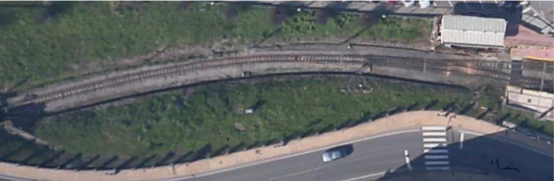
The track section analyzed is located at Solares, a town placed 20km at the southeast of Santan-der. The FEVE line studied works between Santander and Liérganes and it has the same charac-teristics in all the length, except the new replaced sleepers. The point where the measurements were realized is located few meters at the south of Solares station.
Latin American Journal of Solids and Structures 11 (2014) 2241-2254
The line is metric width section with mixed traffic. The platform presents a rail UIC 45Kg/m, with ballast, and the sleepers disposed are concrete sleepers and wood sleepers, being the last ones the most unstable. There are sections with joints and others with rail welded bar, also the subjec-tions and pads are stiff in some secsubjec-tions.
Figure 2: Joint at the studied section.
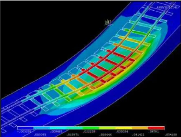
The line was built almost 100 years ago, and was in a poor maintenance conditions. There were great transversal displacements of the rail produced by the lost of transversal resistance along with the rail dilatation. In Figure 3 is shown a model representing the transversal dis-placements of the track which presented the section. Instabilities phenomena as buckling, caused incompatible strains with the normal operation of the line. And finally, the derail-ments produced the last years have promoted the actuation to solve the existing problems.
Figure 4: Transversal displacements presented by the track before replacing the sleepers.
Latin American Journal of Solids and Structures 11 (2014) 2241-2254
Figure 4: Prototype of concrete sleeper disposed at the section.
Figure 5: Concrete sleeper disposed on the section.
The great resistance results obtained with the concrete sleeper allowed replacing only part of the sleepers. The final distribution is shown in Figure 6.
Figure 6: Sleepers distribution and sleepers measured.S1,S4 →Concrete sleeper.S2-S3→Wood sleeper.
Latin American Journal of Solids and Structures 11 (2014) 2241-2254 3.3 Data collection
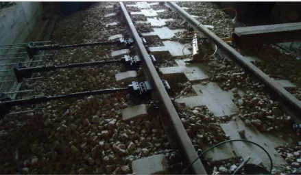
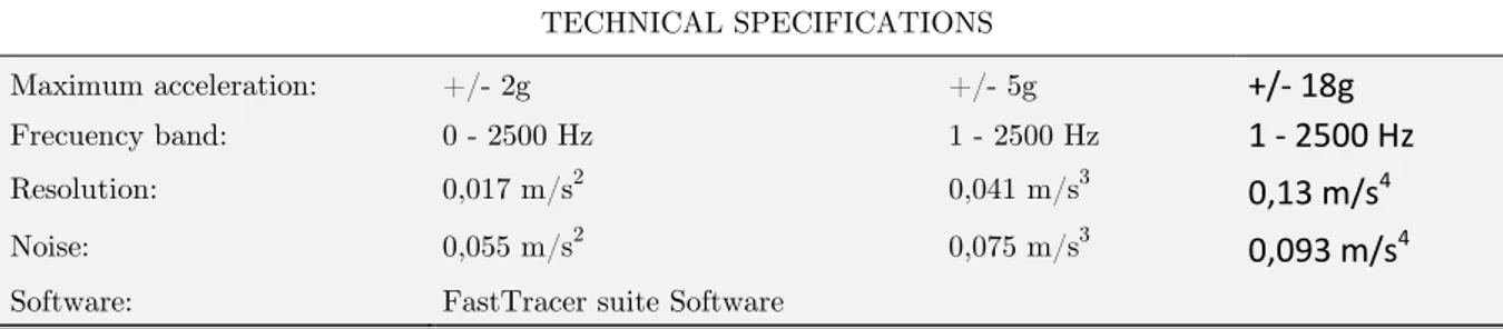
This study starts with measurements taken when the trains were passing using Sequoia FastTrac-er triaxial accelFastTrac-erometFastTrac-ers based on MEMS technology accelFastTrac-erometFastTrac-ers, which charactFastTrac-eristics are shown in table 1.
TECHNICAL SPECIFICATIONS
Maximum acceleration: +/- 2g +/- 5g +/‐ 18g
Frecuency band: 0 - 2500 Hz 1 - 2500 Hz 1 ‐ 2500 Hz
Resolution: 0,017 m/s2 0,041 m/s3 0,13 m/s4
Noise: 0,055 m/s2 0,075 m/s3 0,093 m/s4
Software: FastTracer suite Software
Table 1: Sensor technical specifications.
The sensors were located 4 on the curve section and 4 on the straight section. On both sections is one in each sleeper and in the rail above the others sensors. This distribution provides data from different representative points allowing comparing the influence of both sleepers to the vibrations. Rail sensors were located at the web and sleeper sensors at the extreme of the sleeper. The sleep-ers where the sensors are located are shown in figure 6.
Accelerations were registered for the trains passing within a day. Once the measurements were taken, the accelerations were imported and processed with the software proportionated by the manufacturer.
Once the data was transformed into analyzable files, it was treated with the software Mathe-matica 8. First of all, the accelerations on the vertical axle were taken and cleaned up of the noise. After that, the measurements data were plotted in acelerograms. In addition, frequency spectra were obtained applying the Discrete Fourier Transform (DFT). Average 1/3 octave Spec-tra were obtained too using the software SIGVIEW. These are useful to obtain the main frequen-cies that were assumed to be related to the different rail defects present on the section.
Due to there are different vehicle classes running on the line, some measurements have not been possible to use at the study. The different characteristics of some trains do not allow comparing the measurement and has been dismissed. Despite that, the dismissed measurements have served to check the results.
4 RESULTS
4.1 Comparison straight/curve
In this first comparison is observed the different behavior between the sensor located at the straight section and the curve section on the concrete sleeper.
Latin American Journal of Solids and Structures 11 (2014) 2241-2254
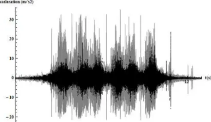
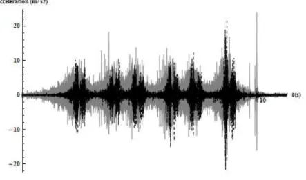
The values obtained for the wood sleepers are around 30 m/s2 for the curve section and 10-15 m/s2 for the straight section. As seen previously, the maximum acceleration value is around 50-60% higher on the curve section.
Figure 7: Sleeper concrete comparison. Curve in grey, straight in black.
Figure 8: Sleeper wood comparison. Curve in grey, Straight in black.
The accelerations on the rail above the concrete sleeper are quite different. On the straight side the maximum peaks are around 140 m/s2 and over 170 m/s2 for the curve side, reaching to 200 m/s2 in some cases.
Latin American Journal of Solids and Structures 11 (2014) 2241-2254
Figure 9: Sleeper concrete. Curve in grey, straight in black.
Figure 10: Sleeper wood. Curve in Grey, Straight in black.
Latin American Journal of Solids and Structures 11 (2014) 2241-2254
and the efforts of the passing trains, so, it is easy to guess that the rail has an important number of irregularities and defects.
4.2 Comparison Wood/concrete Sleepers
Once has been compared the different behavior between the straight and the curve section, it is going to be compared the different vibrational response for both sleepers.
First, is compared the vibration transmission on the straight side for the concrete and wood sleepers. The maximum values are quite similar in the most of the measurements, but there is difference within both sleepers behavior. First, as it is seen on the acelerograms represented, the maximum peaks are quite similar in both sleepers and some of them are slightly lower in concrete sleeper, but is not enough to say that there is an important decrease. Secondly, the pass of the bogie is much more defined in the concrete sleeper. This is due to the bigger stability that pre-sents the concrete sleeper.
Another aspect which emerges is that the pass of the bogies are more defined in the concrete sleeper acelerogram, having similar maximums accelerations both sleepers, they are much more defined and clear on the concrete sleeper.
In the Curve section, the contrast is really important as it is seen on the represented data. The acceleration values on the concrete sleeper are much lower than in the wood sleeper, being around a 33% of the wood sleeper values. The values are around 10 m/s2 for the concrete sleeper and around 30 m/s2 for the wood sleeper.
Latin American Journal of Solids and Structures 11 (2014) 2241-2254
Figure 12: Curve section. Sleeper wood in grey, sleeper concrete in Black.
The rail measurements are quite different depending on where they are taken.
On the straight section the accelerations above the concrete sleeper are slightly higher than above the wood sleeper. But there are maximum isolated peaks that make the difference greater, reach-ing to 100 m/s2 above the concrete sleeper front the 50 m/s2 of the neighbor wood sleeper. Meanwhile the differences in the straight section presents no great differences, in the curve sec-tion they are really different. Above the concrete sleeper there are values higher than 120 m/s2 reaching in some cases to 200 m/s2. However, above the wood sleeper the accelerations are be-tween 40 and 80 m/s2.
Latin American Journal of Solids and Structures 11 (2014) 2241-2254
Figure 14: Curve section. Sleeper wood in grey, sleeper concrete in black.
With these comparisons is possible to obtain some conclusions as follow.
First of all, is confirmed the higher accelerations on the curve section in this measurements as happened on the previous comparison.
Is important to recall that the main purpose of this study is know the different behavior between the two different sleepers existents on the section and that differences are known comparing (3) and (4).
The first difference observed are the lower acceleration values registered in the own concrete sleeper in all the cases due to some causes.
First of all, the concrete sleepers presents an increase of weight in front of the wood sleepers, it makes the platform more stable. In addition, concrete, in contrast to wood, presents an isotropic behavior , it provides a better vibrational answer in all the axis.
The other conclusion which emerges from the data is the rise of the acceleration values in the rail above the concrete sleeper. It is due to the different pads installed on concrete and wood sleepers.
The pads have a big influence in the vibration damping, and it should be studied to know deeply its behavior. The most determinant factor is the rigidity of the pads. Despite the pad are a flexible element in front of the other track section elements, the variation of its rigidity has a big influence for damping the vibrations produced by the pass of the train.
On the wood sleepers are disposed a steel stiff pad, as happen with the subjections. With the stiff pads the vibration along the rail is restricted, but it is transmitted to the sleepers, that its movement is the same as the rail. This kind of pads propitiates the vibration transmission to the track structure, the soil and the neighboring structures, being considered as an externality.
Latin American Journal of Solids and Structures 11 (2014) 2241-2254
Figure 15: Illustration the effect of the stiffness of the Pads. D. Thompson (2009)
4.3 Spectra analysis
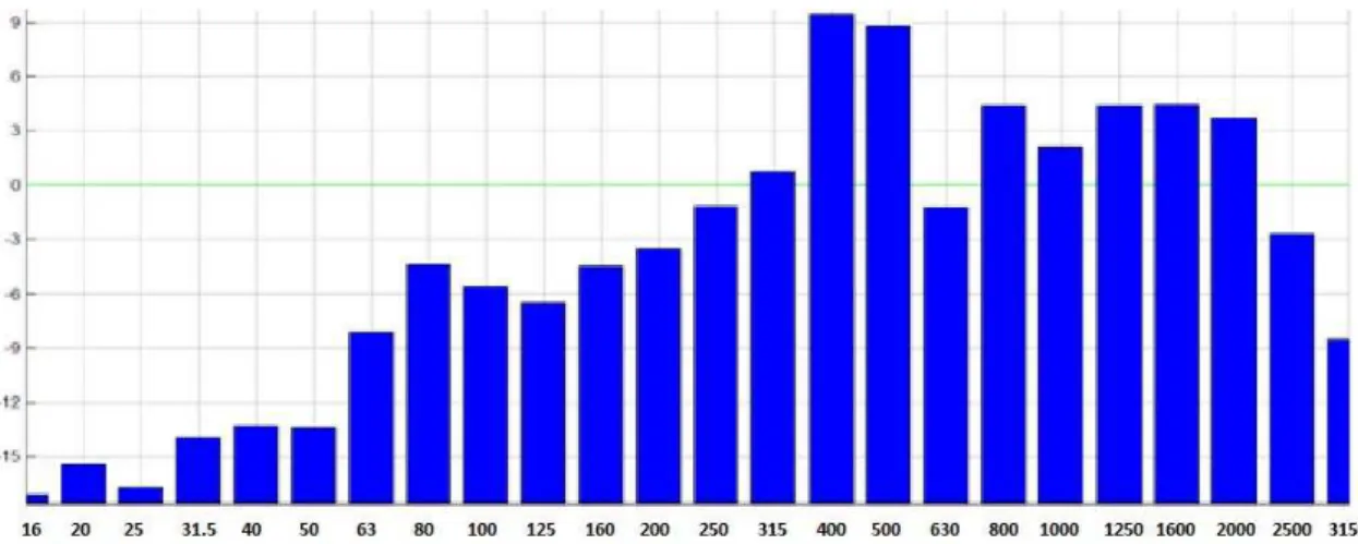
The figures showed below are the average 1/3 octave spectrums for each sleeper. Both of them presents different vibration patterns.
Fig 15 shows the average spectra of the Wood sleeper. It shows a peak around the 400-500 Hz bands and noticeable amplitude in the range 315-2000 Hz.
The average spectra of the concrete sleeper showed in fig 16 presents a peak in the band of 160 Hz and a small peak in the band of 400 Hz. It presents a noticeable amplitude in the range of 63-160 Hz.
The differences are easily observables. The amplitudes are quite lower in the concrete sleeper spectra, which means a better attenuation of the vibrations. Other remarkable difference is the different frequency of the maximum peaks. Peaks have lower frequencies on the concrete sleeper. Although they present lower amplitudes than the wood sleeper, is important to pay attention to this trend because the low frequencies are the most disturbing for people.
Latin American Journal of Solids and Structures 11 (2014) 2241-2254
Figure 16: Average 1/3 octave spectra of concrete sleeper.
5 CONCLUSIONS
This article has presented the research about the different vibrational answer of the two different sleepers exited by the train passing, the original wood sleepers of the railway, and the new con-crete sleepers designed especially for this railway section.
The line is an almost centennial line and presented great transversals displacements that were solved replacing some sleepers by the new concrete sleepers. Once replaced the sleepers, the vibra-tions were measured on site and the data were introduced and treated with the software Mathe-matica 8 for obtain the accelerometers and the frequency spectra of all measurements.
It has allowed knowing the different vibrational response depending on where the sensors were located and why it happens.
As would be logical, the vibrations in the concrete sleeper are lower than in the wood sleeper, being the difference greater on the curve section. It was expected due to the weight increase of the sleeper, and the stability that the special design of the concrete sleeper provide to the section.
Latin American Journal of Solids and Structures 11 (2014) 2241-2254 References
Auersch, L. (2005). The exitation of ground vibration by rail trafic: Theory of vehicle-track-soil interaction and measurements on high-speeed lines, Journal of Sound and Vibration 284103-132.doi:10.1016/j.jsv.2009.10.007. Çalim, F.F. (2009). Dynamic analysis of beam on viscoelastic foundation, Europeal Journal of Mechanics A/Solids 28 469-476.
Coulier., P., François, S., Degrande, G., Lombaert, G. (2012). Mitigation of railway induced vibrations by means of subgrade stiffening, Proceedings of International Conference on Noise and Vibration Engineering (isma2012) / International Conference on Uncertainty in Structural Dynamics (usd2012), 2837-2851. 978-90-73802-89-6.
Florez, E.G., Cardona i Foix, S., Jordi Nebot, S. (2007). Time-Frequency analysis of vibration signals taken on the foot from rail duringpass of train, Siencia er Technica 35 243-247.
Galvín, P., Domínguez, J. (2007). Analysis of ground motion due to moving surface loads induced by high-speed trains, Engineering Analysis with boundary Elements 31 931-941.
Katou, M., Matsuoka, T. , Yoshioka, O., Sanada, Y., Miyoshi, T. ,(2008). Numerical simulation study of ground vibrations using forces from wheels of a running high-speed train, journal of sound and vibration 318 830-849. doi:10.1016/j.jsv.2008.04.053.
Koizol, P., Mares, C. , Esat, I., (2008).Wavelet approach to vibratory analysis of surface due to a load moving in the layer, International Journal of Solids and Structures 45 2140-2159.
Lombaert, G., Degrande, G. (2009). Ground-borne vibration due to static and dynamic axle loads of Intercity and high-speed trains, Journal of Sound and vibration 319(3-5) 1036-1066.doi:10.1016/j.jsv.2005.08.059.
Mazilu, T. (2007). Green's functions for analysis of dynamic response of wheel/rail to vertical exitation, Journal of Sound and vibration 306 31-58. doi:10.1016/j.jsv.2007.05.037.
Metrikine, A.V., Vrouwendelder, A.C.W.M. (2000). Surface ground vibration due to a moving train in a tunnerl: two-dimensional model, journal of sound and vibration 234 (1) 43-66.
Muscolino, G. , Palmeri, A. (2007). Response of beams on viscoelastic damped foundation to moving oscillators, International Journal of Solids and structures 44 150-158.
Real., J., Galisteo, A.,Real, T., Zamorano, C. (2012). Study of wave barriers design for the mitigation of railway ground vibrations, Journal of Vibroengineering vol. 14, issue 1, 2012, p. 408-422 , ISSN: 1392-8716.
Schevenels, M., Lombaert, G., Degrande, G., Cloteau, D. (2007). The wave propagation in a beam on a random elastic foundation, Probabilistic Engineering Mechanics 22 150-158.
Sheng, X., Jones, C.J. , Thompson, D.J. (2006). Prediction of ground vibration from trains using the wave-number finire and boudary element methods, Journal of Sounds and Vibration 293575-586. doi: 10.1016/j.jsv.2005.08.040.
Yang, Y.B., Hung, HH. , (2008). Soil vibrations caused by underground moving trains, Jpurnal of Geotechnical and Geoenviromental Engineering 11 (134) 1633-1644.