Abstract
The post-buckling behavior of composite ships’ stiffened plate panels has been studied. In this study, the average strain- average stress curves for these panels are derived using progressive failure method as well as nonlinear finite element method. The boundary conditions are appropriate for the continuous plate panels used in shipbuilding. The effects of the aspect ratio, initial geometrical imperfection and stiffener size on the post-buckling of these stiff-ened panels are evaluated.
Keywords
Progressive failure analysis, hat stiffened plate panel, initial imper-fection, Finite Element Method (FEM).
Parametric study on average stress–average strain curve
of composite stiffened plates using progressive failure method
1 INTRODUCTION
The application of composite materials in marine industries is so ever-increasing that nowadays high- and medium-length ships are being built of them. Besides, assessment of the ultimate strength of composite ships is of great concern owing to their great lengths. It is clear that the composite stiffened plate panels are the main building components of such ships and thus, derivation of their average stress – average strain curves plays an important role when estimating the ultimate strength of composite ships.
Investigation of the behavior of composite panels during failure is a very complicated task be-cause of the complexity in calculating failure modes as well as the responses of composite materials. Many studies have been performed on mitigating the risks embedded in designing these structures, and numerous methods have been put forth for modeling the failure of composite materials one of which is progressive failure method. As known, in this method, the applied load is increased incre-mentally and the state of the structure is then examined at each stage of loading by using one of the failure criteria. If a failure occurs in one laminate, the mechanical properties of that certain
lam-Fattaneh Morshedsolouk a Mohammad Reza Khedmati b *
a Department of Marine Technology,
Amirkabir University of Technology, Tehran 15914, Iran, [email protected] bDepartment of Marine Technology,
Amirkabir University of Technology, Tehran 15914, Iran, [email protected] * Corresponding Author
Latin American Journal of Solids and Structures 11 (2014) 2203-2226
inate are reduced according to the applied model. Since the failure criteria of composite materials can be applied providing that the stress distribution in structure is precisely given, it is necessary to compute stress distribution by finite element or finite strip methods in progressive failure method
.
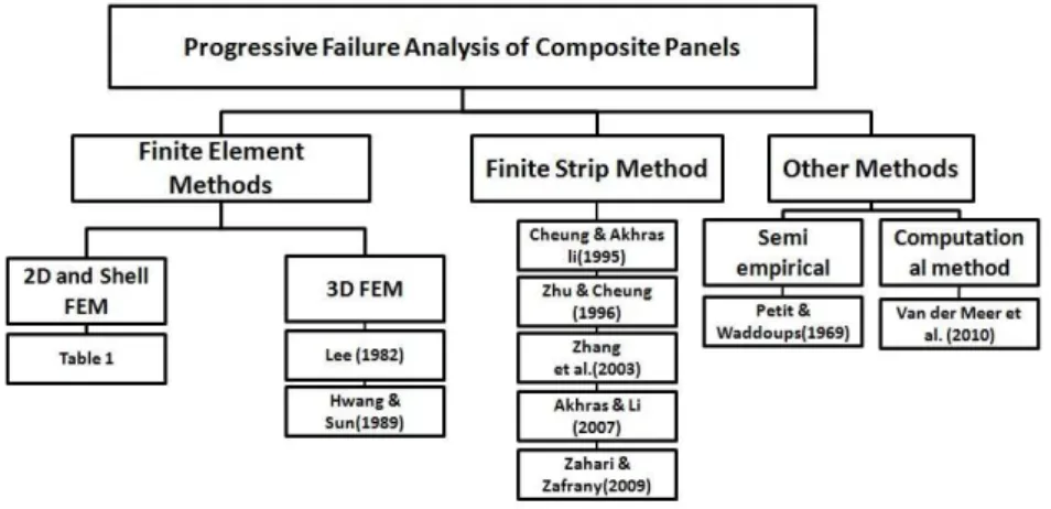
In addition, the study on the behavior of the composite materials by using progressive failure method has attracted many researchers. Figure 1 illustrates a history of the major studies carried out in this field based on different stress analysis methods such as finite element and finite strip ones. In these researches, various failure criteria like Tsai-Wu, Maximum stress, Hashin, etc. are utilized.
Figure 1: History of the major studies carried out on progressive failure assessment of composite panels.
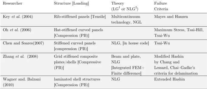
As mentioned earlier, the use of failure criteria for composite materials necessitates the accurate stress distribution. Table 1 lists some research studies conducted by using progressive failure analy-sis based on FEM.
Researcher Structure [Loading] Theory (LG1 or NLG2)
Failure Criteria
Sandhu (1974) Laminated plate Total energy criterion
Sandhu et al. (1983) Composite laminates con-taining a pin loaded hole
Total strain energy failure criterion
Ochoa and Engblom (1987)
Plate+ beam [Tension +
Bending] LG
Piecewise smooth failure criteria
Pandey and Reddy (1987)
Plate with a cutout [In plane
+ Transverse] FSDT3, LG
Maximum stress, maximum strain, Hoffman, Tsai-Wu,
Tsai-Hill
Chang et al. (1984) Laminated plat with a cut
out [Tension] CLPT4, LG
Yamada and Sun , Hahn and Tsai
Chang et al. (1988) Notched laminated plate
[Tension + Compression] CLPT Yamada and Sun
Tan (1991) Damage lamina [In-plane] Tsai-Wu
Latin American Journal of Solids and Structures 11 (2014) 2203-2226
Researcher Structure [Loading] Theory
(LG1 or NLG2)
Failure Criteria
Tolson and
Zarabas (1991) Plate [Biaxial and Transverse] Mindlin Plate theory, LG
Hoffman, Hashin and Lee, Lee and Maximum stress criteria
Averill and Reddy (1992)
Laminated shell structures Micromechanics based model, NLG
Micromechanics based model
Kim and Hong.
(1992) Flat plate with/ without hole
Macroscopic Failure criteria
Tan and Perez (1993)
Laminated composites with a
hole [Compression] Tsai-Wu
Shahid and Chang
(1995) Plate [Tension + Shear] LG
Modifying the existing failure criteria
Daudeville et al. (1995)
Plate with a hole [Tension]
Plate [Tension +Compression] Fracture Mechanics
Eason. and Ochao (1996)
Generate an element for ABAQUS for progressive failure Analysis
Shear deformable element [ABAQUS]
Hashin, Greszczuk, Lee, Maximum Stress, Ochao
Moas and Griffin
(1997) Curved frame [Transverse] NLG
Phenomenological failure criteria
Kim et al. (1998)
A pin loaded laminated com-posite [Shear+ Tension + bearing]
Hashin
Singh and Kumar
(1998) Thin Plate [Shear (PB
5)] FSDT , NLG
Tsai–Hill, Maximum stress
Kong et al. (1998) Stiffened structure
[Compres-sion (PB)] Maximum stress
Baranski and
Biggers (1999) Plate [Compression (PB)] NLG [ABAQUSE] Modified Hashin’s
Gummadi (1999) Laminated beams and arches Total Lagrangian method, NLG
Lee , Hashin , Maximum Stress
Spottswood and Anthony N (2001)
A thin, curved composite panel [Transverse]
simplified large
displac-ment/rotation theory, NLG Hashin
Xie and Biggers (2003)
Flat plates and curved panels with a central cutout [Compression (PB)]
LG/ NLG,
[ABAQUSE] Modified Hashin’s
Damodar et al. (2004)
Curved panels with/ without a circular cutout [Compres-sion (PB)]
NLG, Imperfection
[ABAQUS] Hashin
Goyal et al (2004) Plate with circular hole
[Compression (PB)] NLG, [ABAQUS]
Modified Hashin by Chang and Lessard .
Latin American Journal of Solids and Structures 11 (2014) 2203-2226
Researcher Structure [Loading] Theory
(LG1 or NLG2)
Failure Criteria
Key et al. (2004) Rib-stiffened panels [Tensile] Multicontinuum technology, NGL
Mayes and Hansen
Oh et al. (2006) Hat-stiffened curved panels [Compression (PB)]
Maximum Stress, Tsai-Hill, Tsai-Wu
Chen and Soares(2007) Stiffened curved panels [compression (PB)]
NLG, [in house code] Tsai-Wu
Zhang et al. (2008) Grid stiffened composite plates/shells [Compressive (PB)]
Beam and plate, NLG
[Integrated FEM+ Finite difference]
Modified Hashin by Chang and
Lessard, Chai–Gadke’s criteria for delamination Wagner and. Balzani
(2010)
laminated shell structures [Compression (PB)]
NLG Extended Hashin
1 Linear Geometry 2 Nonlinear Geometry
3 First Order Shear Deformation Theory 4 Classical Laminated Plate Theory 5 Post-buckling
Table 1: A summary of key previous studies carried out on composite structures using progressive failure and finite element methods (continued)
Moreover, the studies carried out on progressive failure by using Finite Strip Method (FSM) are very sparse. To name a token, FSM was, for the first time, used in progressive failure analysis by Cheung et al. (1995) aiming at investigating the behavior of aniotropic panels by using Li failure criterion. In another research, Akhras and Li (2007) used FSM and progressive failure method in order to analyze thick composite plates and imposed Li failure criterion.
Furthermore, Zahari and El-Zafrany (2009) proposed a model for analyzing the failure of stiff-ened plates and composite panels by using FSM on the basis of Mindlin theory. They, also, com-pared the results with those elicited from ABAQUS FEM and found good conformity.
Petit and Waddoups (1969) used the progressive failure method for the first time and applied Classical Laminated Plate Theory (CLPT) for stress analysis. They first calculated the compression and shear values by means of tensile and compression test. The stiffness matrix was then updated at each loading step and finally, the failure point occurred when the stiffness matrix became singu-lar. Van der Meer et al. (2010) developed a computational method for progressive failure analysis in which fiber failure and matrix cracks were analyzed using continuum mechanics.
Latin American Journal of Solids and Structures 11 (2014) 2203-2226
2 PROGRESSIVE FAILURE ANALYSIS METHOD
Progressive failure of composite materials is considered in the current analyses for study of post-buckling strength of composite panels utilizing Tsai-Wu failure criterion. After modeling, meshing and initial loading, the values of stresses and deformations are calculated. Then, the magnitude of the failure parameter is computed based on failure criterion. Afterwards, all layers of each of the components are examined aiming at controlling the occurrence of the failure. If failure occurs, the mechanical properties of the materials approach almost zero in the relevant layer.
At the next step, the force is increased incrementally and the above mentioned procedure is re-peated until the final failure occurs and the ultimate strength or buckling strength of composite panels is eventually acquired using progressive failure method.
If the stacking of plate and stiffeners are not the same or there are several types of stacking in the structure, the states of all layers should be investigated for the applied finite elements and the inferred stresses in each layer have to be transferred to the relevant coordinate system and the magnitude of stresses is considered in the certain failure criterion.
3 CHARACTERISTICS OF FINITE ELEMENT MODELS
In this section, boundary and loading conditions, the material of the plates and its properties, the applied software, the type of finite element in use and the reason for its selection are discussed. The plate models examined in the present study are of the structural components of the ships that can be found in such sections as deck, bottom, sides, bulkheads and tanks. These structures are analyzed to infer their average stress – average strain curves for calculating the final strength of the ship. Note that the average stress – average strain curves of these models are obtained by using progressive failure analysis method.
Latin American Journal of Solids and Structures 11 (2014) 2203-2226
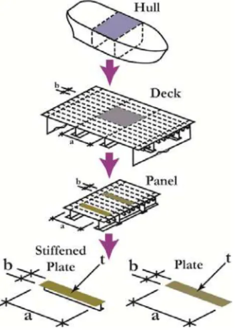
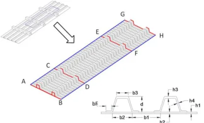
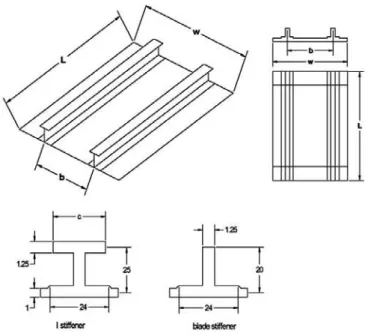
The plates of a ship structure are strengthened by transverse and/or longitudinal stiffeners. The extent of plate models with stiffeners and its relationship with other structural areas of a ship is presented in Figure 2. The strength of stiffened and unstiffened plate panels can be separately stud-ied by applying real boundary conditions. The extent the models is somehow chosen that each mod-el includes two transverse and longitudinal stiffeners as shown in Figure 3.
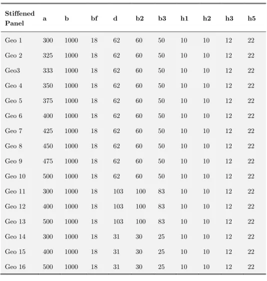
All modeled plates have the aspect ratio of 2 to 3 which is exactly same as that of the real plates used in the structure of composite ships. The geometric and dimensional characteristics of the se-lected stiffened plates are given in Table 2.
Figure 3: Extent of Finite Element Model.
Mechanical Properties Symbols Magnitude
Module of Elasticity in main direction of the material
1
E
15 GPaModule of Elasticity in direction normal to main
direc-tion of the material
E
213.5 GPa
Shear Modulus in direction 12 and 13
12
,
13G G
3.45 GPa Shear Modulus in direction 2323
G
3.45 GPaTensile strength in direction 1
T
X
238 MPaCompression strength in direction 1
C
X
210 MPaTensile strength in direction 2
T
Y
204 MPaCompression strength in direction 2
C
Y
224 MPaShear strength in direction 12
12
S
84 MPaShear strength in direction 13
13
S
84 MPaShear strength in direction 23
23
S
84 MPaLatin American Journal of Solids and Structures 11 (2014) 2203-2226
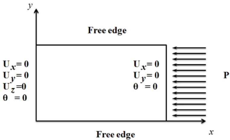
The proper selection of boundary conditions and the correct way to apply them on the model is one of the most significant parts of the modeling. If the conditions do not match the reality, then the solutions results will not be reliable, generalizable and valid. The boundary conditions strictly de-pend on the aspect ratio of the plates in the investigation of the strength of the stiffened plates.
Figure 4: Boundary conditions and dimensions of the Finite Element Model.
Figure 4 shows a finite element model of a stiffened plate. The area of the model is so that it in-cludes two longitudinal and two transverse stiffeners. Lines AB, BH, GH and AG represent the boundaries of the model and lines CD and EF demonstrate where web frames or transverse stiffen-ers are located. Given that transvstiffen-erse stiffenstiffen-ers are stiffer than the longitudinal ones; their lateral deformation is assumed to be zero.
The boundary conditions of the stiffened plates are as follows:
‐ In the case of symmetrical stiffeners, the symmetrical conditions are applied along the lines AG and BH.
‐ In the case of odd and even dimensional ratios, the periodic continuous or symmetry conditions are applied in transverse lines AB and GH in Figure 4, respectively.
‐ Since transverse beams are not modeled, the deformation of plate points along z axis is con-strained to transverse web frame location. Therefore, the deformation of the points is bounded to the lines CD and EF along z. Furthermore, the longitudinal deformation of the plate is cou-pled in the place of the effect of compressive force.
In this research, it is attempted to present the results as practical as possible; thus, the dimensions and materials used in parametric study are same as those prevalent in shipbuilding. Table 3 tabu-lates the mechanical characteristics of the applied composite.
Latin American Journal of Solids and Structures 11 (2014) 2203-2226
modeling were carried out by a macro code written in the ANSYS Programming Design Language (APDL).
Owing to the fact that the stiffened plate elements of ships are thin-walled, their out-of-plane stress is negligible but their in-plane stress is determinant. Hence, the modeling of these components is precise enough with shell elements. Therefore, the element Shell 181, that is appropriate for mod-eling the thin and relatively thick plates and is constructed based on Classic Plate Strain and Mindlin theories, was used in the analyses. These elements are composed of 4 nodes and each node has 6 degrees of freedom. This element is appropriate for linear and nonlinear solutions with large deformations and great angle variations. Also, this element can be used for modeling the composite and laminated materials.
Stiffened
Panel a b bf d b2 b3 h1 h2 h3 h5
Geo 1 300 1000 18 62 60 50 10 10 12 22
Geo 2 325 1000 18 62 60 50 10 10 12 22
Geo3 333 1000 18 62 60 50 10 10 12 22
Geo 4 350 1000 18 62 60 50 10 10 12 22
Geo 5 375 1000 18 62 60 50 10 10 12 22
Geo 6 400 1000 18 62 60 50 10 10 12 22
Geo 7 425 1000 18 62 60 50 10 10 12 22
Geo 8 450 1000 18 62 60 50 10 10 12 22
Geo 9 475 1000 18 62 60 50 10 10 12 22
Geo 10 500 1000 18 62 60 50 10 10 12 22
Geo 11 300 1000 18 103 100 83 10 10 12 22
Geo 12 400 1000 18 103 100 83 10 10 12 22
Geo 13 500 1000 18 103 100 83 10 10 12 22
Geo 14 300 1000 18 31 30 25 10 10 12 22
Geo 15 400 1000 18 31 30 25 10 10 12 22
Geo 16 500 1000 18 31 30 25 10 10 12 22
Table 3: Dimensions of the studied stiffened panel models.
Latin American Journal of Solids and Structures 11 (2014) 2203-2226
meshes and 15 transverse meshes is finally chosen for the plates. Also, the density of 2 meshes in the height of web, 2 ones in the width of flange and 40 meshes in the length is considered for stiff-eners.
Given the fact that the mechanical properties of composites vary in different directions, in con-trary to isotropic materials, the failure can take place by a combined effect of the stresses. Thus, various states of failure may occur in the structure and obviously, each criterion per se is not able to predict these states. There are a lot of failure criteria to predict the occurrence of failure. The formulations of some of these criteria are presented as follows:
At a glance, it can be said that the criteria of the failure for composite materials are the same as those of the failure for isotropic ones which include such criteria as Maximum Stress criterion, Max-imum Strain criterion, and Polynomial criterion. The use of a precise mathematical equation for estimating the failure is strictly constrained to the number of the possible states of failure. It is also noted that the required parameters for two-dimensional failure criteria include longitudinal, trans-verse and tensile as well as shear strength. As mentioned above, this study uses Tsai-Wu failure criterion which is in good harmony with experimental results. This criterion is reflected as Equation (1).
1,
2and
12 are the normal stress in direction 1, normal stress in direction 2 and shear stress in direction 12, respectively.2 2 2
1 2 12
1 2 12 1 2
T T C C 12
IJ
1
1
1
1
2f
ı ı
1
X
X
CY
Y
X X
T CY Y
TS
(1)4 VALIDATION
To validate the proposed method, the corresponding results were compared with those of similar studies and the results of strength tests of three kinds of composite structures under compressive load, namely plates stiffened by blade stiffeners, plates stiffened by I-type stiffeners, and plates stiff-ened by hat-type stiffeners. The first two tests were done by Kong et al. (1998) and the last one was done by Smith and Dow (1985).
4.1 Plates with blade and I-type stiffener
Kong et al. (1998) studied composite plates stiffened by I-type and blade stiffeners under the pres-sure. The details of the models are shown in Figure 5. The other specifications of the models can be listed as follows:
-The length of the plates was 280 mm out of which 15 mm from both ends were being fitted inside the test machine; therefore, the effective length equals 250 mm.
- The loading was in-plane compressive type imposed on both ends as illustrated in Figure 6. - The ends were considered as perfectly clamped.
Latin American Journal of Solids and Structures 11 (2014) 2203-2226
Figure 5: Kong et al. (1998) test model.
Mechanical Properties Symbols Magnitude
Module of Elasticity in main direction of the material
E
1 GPa 130Module of Elasticity in direction normal to main
direc-tion of the material
E
2 10GPaShear Modulus in direction 12 and 13
G
12,
G
13 4.85GPaShear Modulus in direction 23
G
23 GPa 3.62Tensile strength in direction 1
X
T 1933 MPaCompression strength in direction 1
X
C 1051 MPaTensile strength in direction 2
Y
T 51MPaCompression strength in direction 2
Y
C MPa 141Shear strength in direction 12
S
12 61MPaShear strength in direction 13
S
13 GPa 130Shear strength in direction 23
S
23 10GPaLatin American Journal of Solids and Structures 11 (2014) 2203-2226
Figure 6: Loading and boundary conditions of the Kong et al. test model (1998).
First, the results of the plates stiffened by blade stiffeners are discussed. As nonlinear analysis is done in which both progressive failure methodology and failure criterion are applied simultaneously. The first failure in panel occurs at the load of 26 kN. Consequently, the decrease of mechanical properties is carried out in components having failed laminate and this process continues until the complete failure of the panel. Note that the panel finally collapses under the load of 27.2 kN.
Figure 7 shows the compressive load – end shortening curve and out-of-plane deformation distri-bution for the panel with blade stiffener. As can be observed in out-of-plane deformation distribu-tion during progressive failure, the third buckling mode occurs in panel after the first failure. Buck-ling, first, happens under the load of about 5 kN and then, at the load greater than buckling initia-tion load, the first failure happens in panel. Eventually, panel collapses after some stages of failure and progressive failure and the death of some failed layers due to the excessive deformation caused by failure and buckling. In this analysis, it is concluded that the greatest failure occurs in the layers of stiffener in such panels and the period from the initiation of failure until final failure and collapse is very short.
Latin American Journal of Solids and Structures 11 (2014) 2203-2226
At next stage, the response of plates stiffened by I-type stiffeners is investigated. The width of stiffener wing is 20 mm in this panel. Also, the whole set at the junction of stiffener to the plate is thicker than the plate, which is considered in the analysis. Given the geometry described for the plate stiffened by I-type stiffener, the meshing process was performed by using meshes with differ-ent sizes. It is noted that some or all layers of the compondiffer-ents may undergo failure at the stage of load increase from failure initiation until the final failure.
Figures indicate that in contrary to panels with blade stiffener, the failure in panel with I-type stiffener occurs more in lamina, and at the moment of failure, panel suffers failure and collapse in central part and in the region lacking stiffener. Load – end shortening curve resulted from the anal-ysis of this type of panel and the results of the other studies (Kong. et al. (1998)) are shown in Fig-ure 8.
Figure 8: Comparison of the present method results for Kong et al. test with previous works (Kong et al. (1998), Misirlis et al. (2009))
As seen in the Figure 8, buckling initiation load is very close to each other in different methods, but as the load is increased, the difference amongst the methods intensifies. In the investigated panels, the progressive failure method does not result in great differences in the results such that the load of failure initiation and that of final collapse are very close to each other and slightly after the first failure, the structure collapses completely. Also, the time for analysis is very short in present meth-od which indicates that it is capable to be used with an acceptable precision. It is finally concluded that the failure mostly occurred in the stiffening layers and their conjunction with the plate.
4.2 Plate with hat-type stiffener
Latin American Journal of Solids and Structures 11 (2014) 2203-2226 a
b
2b
3b
4b
Fb
1h
2h
3h
4h
d
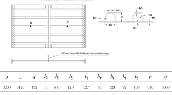
L B 3060 640 108 92 123 54 12.7 12.7 8.6 4 132 6120 3200Figure 9: Dimensions ofSmith and Dow (1985) test model.
Mechanical Properties Symbols Magnitude
Module of Elasticity in main direction of the material
E
1 15 GPaModule of Elasticity in direction normal to main
direc-tion of the material
E
2 13.5 GPaShear Modulus in direction 12 and 13
G G
12,
13 3.45 GPaShear Modulus in direction 23
G
23 GPa 3.62Table 5: Material Properties of the Smith and Dow model test.
According to Smith and Dow (1985), the experiment was conducted in a specific steel grillage ma-chine. Also, the force was progressively increased and then was decreased to zero in some stages in order to make it possible to investigate the failures.
As the authors reported, the force was increased to the stress of 25 kg.m-2, while deformation was invisible, but after exceeding this stress threshold, a whole deformation started to occur in pil-lar pole mode. Also, the longitudinal stiffeners started to deform upwardly in one side of the bulk-head and to deform downwardly in the other side.
Latin American Journal of Solids and Structures 11 (2014) 2203-2226
Figure 10: Finite Element model of the Smith and Dow test
It is assumed that the properties of materials are constant during all stages of the solution until the time before the failure, whereas after the failure, the properties of material start to decrease in the layers and components related to the location of failure. It is also supposed that the initial defor-mations with the range of
w
opin local buckling mode and with the range ofw
osin the totalbuck-ling mode occur in the structure concurrently. It is noted that the range of these deformations matches the maximum deformations measured in laboratorial model which are equal to
0005
.
0
a
w
opand
0
.
0013
a
w
os , respectively.Obviously, the deformations are slight until the stress threshold of >29 MPa and over this threshold, total buckling occurs and finally, a downward span and another upward hatch buckle. Also, the results report that the failure starts in the hatch that buckles downwardly and quickly proceeds in the width of longitudinal stiffeners. It should be mentioned that the failure does not proceed toward the inside of the plate. Figure 11 shows the diagram of vertical deformation of two points P and Q in terms of average stress which is compared with Smith's analysis. Note that point P moves upwardly and point Q moves downwardly. Therefore, the deformation of point P is shown on the right of diagram and that of Q on the left side.
Latin American Journal of Solids and Structures 11 (2014) 2203-2226
The failed elements at the threshold of ultimate strength achievement calculated by the proposed method and the spot of failure in the experiment are represented in Figure 12. To make a conclu-sion, as explained earlier, the results of calculations are in agreement with the results of the experi-ment carried out by Smith and Dow (1985).
Figure 12: Fractured element in present model and Smith and Dow test model.
5 BUCKLING AND POSTBUCKLING BEHAVIOR OF STIFFENED PLATES
5.1 Effect of dimensional ratio on buckling and post-buckling behavior of stiffened flat plates
To study the effect of aspect ratio of stiffened plates on buckling and post-buckling behavior, 10 rectangular stiffened plates with the aspect ratios used in shipbuilding were analyzed. The geomet-ric characteristics of these models named Geo1 to Geo10 are presented in Table 2. It is worth men-tioning that the behavior of stiffened plates depends on their aspect ratio. Also, the behaviors are determined on the basis of the boundary conditions explained in the previous sections.
In stiffened plates with odd or close to odd aspect ratios, the deformation was in the form of one half-wave occurred along each span. In these stiffened plates, in the half-wave where the defor-mation is downward, the first failure occurs in stiffener and grows within the width, length and layers of the stiffener and stops as soon as it reaches the plate. At this stage, stiffened plate ap-proaches its final failure limit. In addition, no considerable differences were observed in average stress – average strain curve for the plates with different odd aspect ratios.
Latin American Journal of Solids and Structures 11 (2014) 2203-2226
Figure 13: Average stress – average strain curves for stiffened plates having different aspect ratios.
Figure 14: Average stress – average strain curves for stiffened plates having different aspect ratios.
Latin American Journal of Solids and Structures 11 (2014) 2203-2226
Figure 15: Absorbed energy up to collapse and ultimate strength of the stiffened panel with different aspect ratios.
5.2 Effect of dimensional ratio on buckling and post-buckling behavior of stiffened flat plates
Considering the approximately similar behavior of stiffened plates with odd aspect ratios to each other as well as the almost analogous behavior of those with even aspect ratios to each other, three geometries of Geo 1, Geo 6 and Geo 10 were selected in order to study the effect of initial defor-mation on the buckling and post-buckling responses in stiffened plates. These geometries were cho-sen because it is generally tried, in designing ship structures, to somehow choose the spacing be-tween stiffeners that facilitates the building process too.
The deformation function for plates with odd aspect ratios is considered to be a sinusoidal one with one half-wave in a span and the corresponding function for plates with even aspect ratios is supposed to be, again, a sinusoidal function, but, with two half-waves along the length. The magni-tude of maximum initial deformation equals
Im. The magnitude of
Im is regarded as 1, 3, 5 and 7 mm.Latin American Journal of Solids and Structures 11 (2014) 2203-2226
Figure 16: Average stress – average strain curve for plate panel with aspect ratio of 3.33 and different magnitudes of initial imperfection.
Figure 17: Average stress – average strain curve for plate panel with aspect ratio of 2.5 and different magnitudes of initial imperfection.
Latin American Journal of Solids and Structures 11 (2014) 2203-2226
The figures reveal that the total behavior of plates with different magnitudes of initial defor-mations is not much varied and average stress – average strain curves have similar forms within each group of plates. The failure trend of plates with odd aspect ratios is quite similar. Note that the failure, firstly, occurs in stiffener and as the load is increased, the failed region starts to be quickly extended along the thickness and width of the stiffener and the plate reaches its ultimate strength. The state of ultimate strength happens in stiffener and develops around it.
Figure 19: Ultimate strength of the stiffened panel with initial imperfection.
Figure 20 Absorbed energy up to collapse by stiffened panel with initial imperfection.
Latin American Journal of Solids and Structures 11 (2014) 2203-2226
5.3 Effect of stiffness of stiffeners on buckling and post-buckling behavior of stiffened flat plates
In order to examine the impact of the stiffness of the longitudinal stiffeners on ultimate strength of composite ships, three categories of stiffened panels with the aspect ratios of 2, 2.5 and 3.33 were analyzed. These stiffened panels can be categorized into three groups of low, medium and high strength stiffened panels. The models’ categories of these stiffened panels are presented in Table 6.
Aspect Ratio Stiffened Panel Strength Model Name
3.33
High Strength Stiffened Panel Geo 11 Medium Strength Stiffened Panel Geo 1 Low Strength Stiffened Panel Geo 14
2.5
High Strength Stiffened Panel Geo 12 Medium Strength Stiffened Panel Geo 6 Low Strength Stiffened Panel Geo 15
2
High Strength Stiffened Panel Geo 13 Medium Strength Stiffened Panel Geo 10 Low Strength Stiffened Panel Geo 16
Table 6:Categories of these stiffened panels.
The average stress – average strain curves of these stiffeners are given in Figures 21-23 which repre-sent the responses of stiffened plates with the aspect ratios of 3.33, 2.5 and 2, respectively.
Note that Geo 11, Geo 14 and Geo 1 indicate plates with high, low and medium strength, respec-tively. The behavior of stiffened plates Geo 1 and Geo 14 are similar to each other while high strength stiffened panel (Geo 11) exhibits a quite different behavior. Furthermore, in high strength stiffened panel (Geo 11) model, the stiffener remained quite un-deformed and only the plate buck-led. The buckling mode of plate was alike the buckling of the plate with simple supports and was independent of the boundary conditions defined for the plate.
Latin American Journal of Solids and Structures 11 (2014) 2203-2226
In Figure 23, the behaviors of low strength stiffened plates (Geo 15) and medium strength stiffened plates (Geo 6) are similar, but high strength stiffened plate (Geo 12) shows completely different behavior. In high strength stiffened plate model, the stiffener remains quite undeformed and only the plate buckles. The buckling behavior of the plate is similar to that of a plate with simple sup-port and is independent of boundary conditions defined for this plate.
Figure 22: Average stress – average strain curve for plate panel with aspect ratio 2.5 and three different stiffener dimensions.
In Figure 24, the behaviors of low strength stiffened plates (Geo 16) and medium strength stiffened plates (Geo 10) are similar, whereas high strength stiffened plate (Geo 13) shows a completely dif-ferent behavior. This was confirmed in Figure 23 and Figures 24 for other aspect ratios of the plate.
Latin American Journal of Solids and Structures 11 (2014) 2203-2226
6 CONCLUSIONS
The previous studies report sparse researches in the area of stiffened plates used in shipbuilding. In addition, the effect of initial deformation on the strength of composite stiffened plates has not been studied yet.
In this research, the progressive failure method for composite materials was studied and the model was developed and then validated. Next, different forms of the composite stiffened plates used in marine industries were analyzed in terms of different aspect ratios, stiffener dimensions and initial deformation. A set of analyses was carried out based on nonlinear progressive failure method. Afterwards, average stress – average strain curves were derived.
The investigation of the effect of aspect ratio on buckling and post-buckling behavior of stiffened flat plates of a ship revealed that this parameter considerably affects the buckling and post-buckling behavior of stiffened flat plates; because the behaviors of stiffened plates with odd and even aspect ratios are very different. It was also found that the ultimate strength of stiffened plates with odd aspect ratio was almost half of those of stiffened plates with even aspect ratios. However, in the selected range of aspect ratio, the buckling and post-buckling behaviors of stiffened plates with dif-ferent odd aspect ratios are very similar to each other and this phenomenon is also true for stiffened plates with different even aspect ratios.
Finally, within investigation of the initial deformation impact on buckling and post-buckling behavior of composite stiffened plates, the form of initial deformation was considered to be same as the first mode of initial deformation of stiffened plates. It was also concluded that initial defor-mation considerably influences ultimate strength and that when
Im
7
mm
. Note that previous studies have not dealt with the impact of initial deformation on ultimate strength of composite plates.References
Lee, J. D., (1982). Three dimensional finite element analysis of damage accumulation in composite laminate. Compu-tation and Structure 15.3: 335-350.
Huang , W. C., Sun, C. T., (1989). Failure analysis of laminated composites by using iterative three-dimensional finite element method., Computation and Structure 33.1: 41-47.
Sandhu , R. S., (1974). Ultimate strength analysis of symmetric laminates, Wright-Patterson , Air force flight dyna-mics lab Wright-Patterson.
Sandhu, R. S., Gallo, R. L., Sendeckyj, G. P., (1982). Initiation and accumulation of damage in composite laminates, Testing and design(sixth conference).
Ochoa, J. J., Engblom, O. O., (1987). Analysis of progressive failure in composites, Composite Science and Techno-logy . 28.2: pp. 87-102.
Pandey, J. N., Reddy, A. K., (1987). A first-ply failure analysis of composite laminates, Computers and Structures 25: 371-393.
Chang, F. K., Scott, R. A., Springer, G. S., (1984). Failure strength of nonlinearly elastic composite laminates con-taining a pin loaded hole, Journal of Composite Materials 18: 464-477.
Latin American Journal of Solids and Structures 11 (2014) 2203-2226 Tan, SC., (1991). A progressive failure model for composite laminates containing openings, Journal of Composite Materials 25.5: 556–77.
Tolson, N.,Zarabas, S., (1991). Finite element analysis of progressive failure in laminates composite, Computers & Structures 38: 361-376.
Averill, J. N., Reddy, R. C., (1992). Geometrically nonlinear analysis of laminated composite shells using a macro-micro cumulative damage model., Damage Mechanics in Composites, 150 : 255-273.
Kim, C. S., Hong, Y. M. (1992). Progressive failure model for the analysis of laminated composite based on finite element approach, Journal of Reinforced Plastic Composite 11: 1078-92.
Tan, S. C., Perez, J., (1993). Progressive failure of laminated composites with a hole under compressive loading, Journal of Reinforced Plastics Composite 12:1043-57.
Shahid, I., Chang, F.K., (1995). An accumulative damage model for tensile and shear failures of laminated composite plates, Journal of Composite Materials 29: 926–81.
Daudeville, L., Allix, O., Ladeveze, P., (1995). Delamination analysis by damage mechanics: some applications, Composite Engineering 5.1: 17– 24.
Eason, TG, Ochoa, OO, (1996). Modeling progressive damage in composites: a shear deformable element for ABA-QUS, Composite Structures 34.
Moas, E., Griffin, O. H. Jr., (1997). Progressive failure analysis of laminated composite structure, Structural Dyna-mics, and Material Conference.
Kim, SJ,Hwang, JS,Kim, JH , (1998). Progressive failure analysis of a pin loaded laminated composite using penalty finite element method, AIAA Journal 36: 75-80.
Singh, S. B., Kumar, A. ,(1998). Postbuckling response and failure of symmetric laminates under in-plane shear, Composite Science and Technology 58: 1949–60.
Kong, C. W., Lee, I. C., Kim CG, C. G., Hong, C. S., (1998). Postbuckling and failure of stiffened composite panels under axial compression, Composite Structure 42.1: 13-21.
Baranski, A. T., Biggers, S. B. Jr., (1999). Postbuckling analysis of tailored composite plates with progressive dama-ge, Composite Structure 46: 245–55.
Gummadi, L. N. B, (1999). Progressive failure analysis of laminated beams and arches undergoing large rotations, Mechanics of Composite Material and Structure 6: 69-93.
Spottswood, S. M., Palazotto, A. N.,(2001). Progressive failure analysis of a composite shell, Composite Structure 53: 117–31.
Xie, D., Biggers, S. B. Jr.,(2003). Postbuckling analysis with progressive damage modeling in tailored laminated plates and shells with a cutout, Composite Structure 59: 199–216.
Damodar, R. A., Jaunky, N., Hilburger, M., Davila, C. G., (2004). Progressive failure analyses of compression-loaded composite curved panels with and without cutouts, Composite Structures 65: 143–155.
Goyal, V. K., Jaunky, N. R., Johnson ER, E. R., Damodar, R. A., (2004). Intralaminar and interlaminar progressive failure analyses of composite panels with circular cutouts, Composite Structure 64:91–105.
Key, C.T., Garnich, M. R., Hansen, A. C., (2004). Progressive failure predictions for ribstiffened panels based on multicontinuum technology, Composite Structure 65: 357–66.
Oh, S. H., Kim, K. S., Kim, C. G., (2006). An efficient postbuckling analysis technique for composite stiffened curved panels, Composite Structures74: 361–369.
Chen, N.Z., Soares, C. G., (2007). Progressive failure analysis for prediction of post-buckling compressive strength of laminated composite plates and stiffened panels, Journal of Reinforced Plastic and Composites 26. 10: 1021-1042.
Latin American Journal of Solids and Structures 11 (2014) 2203-2226
Wagner, W., Balzani, C., (2010). Prediction of the postbuckling response of composite airframe panels including ply failure, Engineering Fracture Mechanics 77: 3648–3657.
Cheung, M. S., Akhras, G., Li, W., (1995). Progressive failure analysis of composite plates by the finite strip met-hod, Computer Methods in Applied Mechanics and Engineering, vol. 124: 49–61.
Akhras G, G.; Li, W. C., (2007). Progressive failure analysis of thick composite plates using the spline finite strip method, Composite Structure 79: 34–43.
Zahari, R.; Zafrany, A., (2009). Progressive failure analysis of composite laminated stiffened plates using the finite strip method, Composite Structures, 87: 63–70.
Waddoups, P. H.; Petit, M. E., (1969). A method of predicting the nonlinear behavior of laminated composites, Journal of Composite Materials 3: 2-19.
Van der Meer, F. P.; Oliver, C.; Sluys, L. J., (2010).Computational analysis of progressive failure in a notched lami-nate including shear nonlinearity and fiber failure, Composites Science and Technology 70: 692–700.
Misirlis, K., Downes, J., Dow, R.S., (2009). Comparison of progressive failure models for composite materials. Inter-national Conference on Fast Sea Transportation:307-320