This text presents a teaching tool developed for the design of reinforced concrete column. The basic functionality and validation results of the application are shown here. A complete example using the expressions of the Brazilian code for the design of reinforced concrete structures, NBR6118:2003, is also presented.
Keywords: applets, column design, reinforced concrete, teaching tools.
Este texto apresenta uma ferramenta didática desenvolvida para o dimensionamento e detalhamento de pilares de concreto armado. São apre-sentadas as funcionalidades básicas do aplicativo e o processo de validação dos resultados obtidos. Um exemplo de dimensionamento de um pilar utilizando as expressões da norma brasileira de projeto de estruturas de concreto, NBR6118:2003, também é apresentado.
Palavras-chave: applets, dimensionamento de pilares, concreto armado, ferramentas de ensino.
An educational tool for design and detailing
of reinforced concrete columns
Uma ferramenta didática para o dimensionamento
e detalhamento de pilares de concreto armado
A. B. COLOMBO a [email protected]
W. S. ASSIS b [email protected]
T. N. BITTENCOURT c [email protected]
a Aluno de Mestrado, Laboratório de Estruturas e Materiais Estruturais (LEM), Departamento de Estruturas e Geotécnica, Escola Politécnica da Universidade de São Paulo, [email protected], Av. Prof. Almeida Prado, 271, CEP 05508-900, São Paulo-SP, Brasil.
b Professor Adjunto, Laboratório de Computação Cientíica e Visualização (LCCV), Centro de Tecnologia, Universidade Federal de Alagoas, [email protected], Av. Lourival Melo Mota, s/n, CEP 57072-970, Maceió-AL, Brasil.
c Professor Associado, Laboratório de Estruturas e Materiais Estruturais (LEM), Departamento de Estruturas e Geotécnica, Escola Politécnica da Universidade de São Paulo, [email protected], Av. Prof. Almeida Prado, 271, CEP 05508-900, São Paulo-SP, Brasil.
Received: 24 May 2010 • Accepted: 02 Mar 2011 • Available Online: 19 Aug 2011
Abstract
1. Introduction
Multimedia elements as support material in engineering edu-cation have been the focus of researchers in Brazil and in other countries as well (Assis & Bittencourt [1]). JavaTM ap-plets, which are small applications written with the JavaTM
language that can be executed within a web browser, have been shown to be very useful multimedia elements. This type resource enables the student to have access to a tool ca-pable of making complex calculations through a very simple graphical user interface.
Having access to this type of resource in the classroom is espe-cially useful when studying topics that can only be solved with the help of a computer.
2. Application description
The developed software has the objective of designing the reinforcement area for a simply supported reinforced rect-angular concrete column subjected to skew bending. The first step in the program consists of the user inputting the basic loading and geometric data for the problem. The pro-gram then does a second order analysis and determines the minimum and final forces for the reinforcement area
design. In the next step the reinforcement area is deter -mined for a reinforcement arrangement chosen by the user. The last step consists on the detailing of the reinforcement
section with the reinforcement area that was determined in the last step. As this program is a teaching tool some
of these steps require the intervention of the user. In the
items below each of these steps will be further described giving a better notion about the applet itself. The reader
may access the applet on the Internet in the following ad -dress
http://www.lmc.ep.usp.br/pesquisas/tecedu
.2.1 Data input
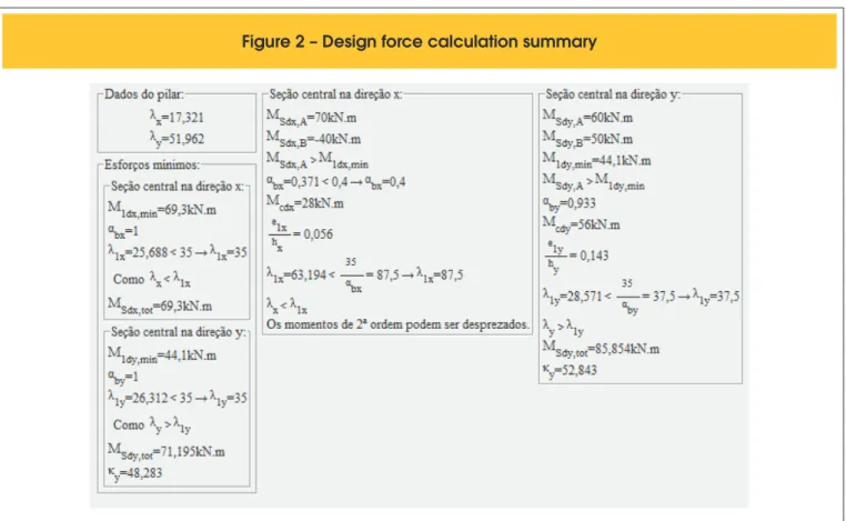
The geometry and loading data for the column is inputted into the screen shown in Figure 1. This data includes the dimensions for the rectangular section, the effective length for the column in the
x and y directions, the normal force acting on the column, the irst
order bending moments acting on the ends of the column, the concrete strength, the reinforcement class and the gross cover for the reinforcement.
2.2 Determining second order effects
The routine adopted in this part of the applet uses the
formula-tions presented by the Brazilian Reinforced Concrete Code
NBR6118:2003 [2]. This routine checks if second order effects are negligible, if they are not, it calculates the second order
ef-fect through a moment magniication equation. Figure 2 shows a
screenshot of this calculation process, this way the student may easily check his work if necessary.
5). The applet checks if the spacing satisies the speciied rules
given by the NBR6118:2003 code, giving a warning to the user
in case the spacing is inadequate. Having deined the longitudi -nal reinforcement, the user must then manually place the neces-sary stirrups. The applet automatically checks if any rebars are not properly tied painting the rebar in a red color (Figure 6(a)). A cross section properly tied by stirrups is shown in Figure 6(b).
3. Results
3.1 Validation of the failure surface
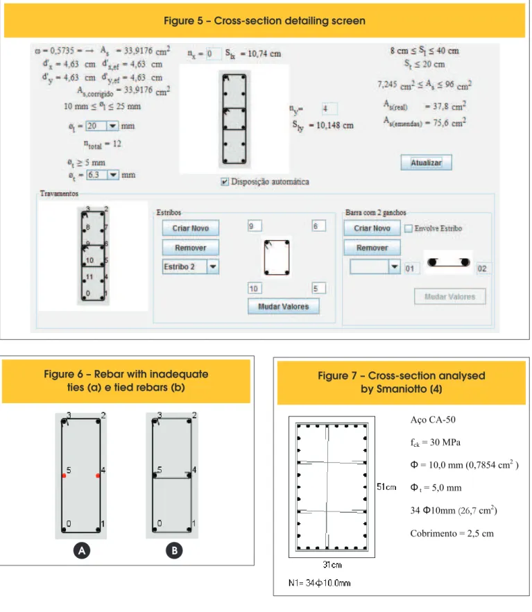
The validation of the failure surfaces generated by the applet was done through comparisons with results presented by Smaniotto [4] and Montoya et. al. [5]. Smaniotto [4] presented a tool for automat-ic design of column cross-sections in biaxial bending. For valida-tion of his work he demonstrated a comparison with the results, for the cross-section shown in Figure 7, from other programs. Figure 8 shows the moment diagrams for a series of normal force values,
here PDOP represents the results for the program by Smaniotto [4], Eberick is a commercial program for building design, nFOCCA
is a program created by Santos [3] and applet represents the re-sults obtained with the tool here presented.
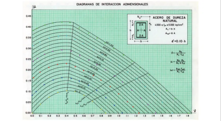
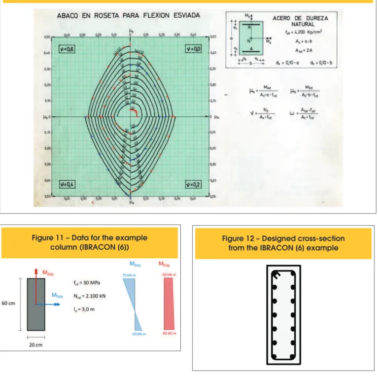
Montoya et. al. [5] presented several interaction diagrams for an array of cross-section types, reinforcement distributions and ratios. These diagrams are commonly used for the manual design of col-umns in Brazil. For data validation purposes the results from the applet were plotted over some of these diagrams Figures 9 and 10 show these results.
2.3 Reinforcement area design
In the next stage the user must choose the bending moment pair
acting on the column section and the reinforcement distribution on
that section. The applet then inds the reinforcement ratio for that
section that has a failure surface that passes through the selected
acting forces. The algorithms used to ind the failure surface can
be found in Santos [3]. Some changes on these algorithms had to be made in order to integrate them into an object oriented pro-gramming structure and also some changes were made to improve performance, these changes include: use of a Newton-Raphson procedure to ind the neutral axis depth and the an adaptive Simp-son method for the numerical integrations necessary throughout the process.
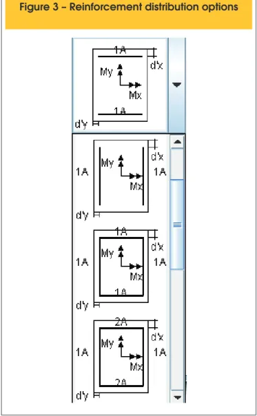
As was mentioned in the last paragraph the user must choose the reinforcement distribution in the cross section of the column, Fig-ure 3 shows some of the distributions available to the user. The gross cover used to position the reinforcement layers shown is
de-termined from the data the user inputted in the irst tab.
After a reinforcement ratio value is found the user may cycle through the acting forces that the column must resist and see if they are inside of the failure curve, Figure 4 shows the failure curve for a given ratio and the possible acting forces.
2.4 Reinforcement detailing
Given the reinforcement ratio calculated in the previous step, the longitudinal rebar diameter and the reinforcement distribution, the program automatically distributes de rebars in the section (Figure
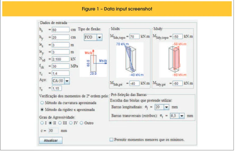
3.2 Design example
In order to give a better understanding of the applet itself a problem from the Technical Commentaries and Examples from the Brazilian Code (IBRACON [6]) will be solved. The problem consists on ind -ing the reinforcement for the column presented in Figure 11. For comparison purposes the design forces for the problem in
IBRACON [6] are presented in Table 1. For these design forces it
was proposed a cross section with stirrups of 6,3 mm and concrete cover of 30 mm and longitudinal reinforcement consisting of four-teen 20 mm rebars, as shown in Figure 12.
Inputting the data from Figure 11 into the applet, gives the results shown in Figure 2, the design forces from this screen are
sum-marized in Table 2. Comparing the results from the two tables it is
shows a difference in the values for the moment in the middle of the column. This difference is due the calculation of the 2nd order effects in the x direction. In the example the 2nd order effects is al-ways calculated in both directions if these effects are signiicant in even only one direction. The Brazilian Code does not mention this practice in its text and therefore the applet only inds the 2nd order moment in the directions that have signiicant 2nd order effects. As can be seen this practice does not change the inal results be -cause the additional 2nd order moment in the x direction is small.
The reinforcement ratio necessary for these acting forces is pre-sented in Figure 4, with the chosen distribution and this reinforce-ment ratio the program arrives in a cross-section consisting of
twelve 20 mm rebars, the inal cross-section is shown in Figure 5.
Failure curves were generated for both proposed cross-sections and the design forces were plotted with these curves in Figure 13.
This igure shows that both solutions are compatible and that the
difference in design force evaluation did not affect the resulting cross-section.
4. Conclusions
The presented tool is a practical solution for designing reinforced
concrete columns. If used as an educational tool, it gives the stu -dent access to a very powerful computing tool replacing the use of interaction diagrams that end up being hardly used in the day to day in engineering design.
The validation presented shows that the applet provides consistent results when compared to other programs and to interaction dia-grams from the literature. Some divergence in the results appear in Figure 8 for normal forces of 3600 kN, these were noted also by Smaniotto[4], and the greater resisting moments shown by the Eberick program are explained by the author as differences in the method of calculation of the resultant of the concrete
compres-sion ield. Santos [3] states that numerical precicompres-sion is guaranteed
when using numerical integration for normal load values less than
99% of the total capacity of the cross-section.
The use of interaction diagrams for reinforcement design in col-umns is less exact than using the applet. This is because these diagrams are generated for gross cover values that are not the real gross cover and therefore corrections to the reinforcement values have to be made. Another fact that create even more inaccura-cies is the fact that, in most cases, it is necessary to interpolate in between diagrams with different normal values and reinforcement
ratio. In the presented design example, it is not clear what tech -nique was used for determining the reinforcement in the
cross-section but the result from the applet used less reinforcement and attended the acting forces.
5. References
[01] ASSIS, W. S., BITTENCOURT, T. N. Desenvolvimento
de uma Ferramenta Didática para o Estudo de
Diagramas de Interação Normal-momento em Colunas de Concreto. Revista Engenharia Civil - Universidade do Minho, Vol. 22, pp.49-58,
Janeiro 2005.
[02] ASSOCIAÇÃO BRASILEIRA DE NORMAS TÉCNICAS. Projeto de estruturas de concreto – Procedimento – NBR-6118, Rio de Janeiro, 2003. [03] SANTOS, L. M. Sub-rotinas Básicas do
Dimensionamento de Concreto Armado. São Paulo: Thot, 1994.
[04] SMANIOTTO, A. Dimensionamento e Detalhamento
Automático de Pilares Retangulares Submetidos à
Flexão Composta Oblíqua. Dissertação (mestrado). Universidade Federal de Santa Catarina,
Florianópolis, 2005.
[05] MONTOYA, P. J., MESEGUER, A. G., CABRE, A. M.
Hormigon armado. Barcelona: Gustavo Gili,
14ª Ed., 1994.
[06] INSTITUTO BRASILEIRO DO CONCRETO – IBRACON. Procedimento NBR 6118:2003 – Comentários Técnicos e Exemplos de Aplicação
da NB-1, São Paulo, 2007.
Figure 5 – Cross-section detailing screen
Figure 6 – Rebar with inadequate
ties (a) e tied rebars (b)
A
B
Figure 7 – Cross-section analysed
by Smaniotto [4]
Aço
CA-50
fck
= 30 MPa
Φ
= 10,0 mm (0,7854 cm
2)
Φ
t= 5,0 mm
34
Φ10mm (26,7 cm
2)
Figure 10 – Comparison of results with interaction diagrams for biaxial bending (Montoya et al. [5])
Figure 11 – Data for the example
Figure 13 – Failure curves for the proposed cross-sections
0.00E+00 5.00E-02 1.00E-01 1.50E-01 2.00E-01 2.50E-01
0 0.02 0.04 0.06 0.08 0.1 0.12 0.14 0.16 0.18 0.2
mx my
applet Cross section from IBRACON[6] Design forces from IBRACON[6] Design forces from applet

![Figure 8 – Comparison of results from applet with other programs (Smaniotto [4])](https://thumb-eu.123doks.com/thumbv2/123dok_br/18859749.417712/7.892.260.633.172.875/figure-comparison-results-applet-programs-smaniotto.webp)