This paper discusses several possible ways to evaluate reinforced concrete frames designed for multiple loor buildings using lat slabs, from the standpoint of instability and second-order loads. Based on loor designs with simple lat slab frames and regular distribution of columns, models with different numbers of loors are considered. The models do not involve highly rigid elements such as staircases and elevator shafts. The model-ing adopts simpliied criteria to design vertical loads, formmodel-ing frames with slab bands representmodel-ing beams of little height. Based on the results, an analysis is made of the validity of the application of the criteria without considering the second-order loads presented in the NBR6118:2003 code. A comparison is also made of the results with and without the use of inverted edge beams.
Keywords: instability, second-order loads, lat slabs.
O presente trabalho aborda maneiras possíveis de avaliar estruturas de concreto armado, sem vigas, destinadas a edifícios de múltiplos pavi -mentos quanto à instabilidade e necessidade de considerações de esforços de segunda ordem. A partir de plantas simples de estruturas em lajes planas, com distribuição regular de pilares, são considerados modelos com diferentes números de pavimentos. Os modelos não utilizam elemen -tos de grande rigidez, como poços de elevadores e escadas. A modelagem utilizada adota os critérios simpliicados para dimensionamento às ações verticais, formando pórticos com faixas de lajes admitidas como vigas de pequena altura. A partir dos resultados, analisa-se a validade da aplicação dos critérios para dispensa de consideração dos esforços globais de segunda ordem apresentados na NBR6118:2003. São compara-dos resultacompara-dos para estruturas com e sem utilização de vigas invertidas na periferia.
Palavras-chave: instabilidade, segunda ordem, lajes lisas.
Stability of reinforced concrete buildings with lat slabs:
inluence of frames with lat slab layers and inverted
edge beams
Estabilidade em edifícios de concreto armado com lajes
sem vigas: inluência de pórticos formados por faixas
de lajes e vigas invertidas nas bordas
L. A. B. CiCoLin a [email protected]
J. R. FigueiRedo FiLho b [email protected]
a Civil Engineer, PETROBRAS; Assistant Professor at CESET/Unicamp – email: [email protected] – Departamento de Engenharia Civil, Universidade Federal de São Carlos – Rodovia Washington Luis, Km 235, Caixa Postal 676 – 13565-905 – São Carlos, SP, Brazil
b Professor, Ph.D., Department of Civil Engineering, Federal University of São Carlos – email: [email protected] – Departamento de Engenharia Civil, Universidade Federal de São Carlos – Rodovia Washington Luis, Km 235, Caixa Postal 676 – 13565-905 – São Carlos, SP, Brazil
Received: 26 Apr 2010 • Accepted: 21 Mar 2011 • Available Online: 19 Aug 2011
Abstract
1. introduction
1.1 Initial considerations
Building design and construction methods have evolved in the search for the rational and eficient use of resources. The civil con -struction sector consumes large volumes of natural resources and energy, thereby causing environmental impacts. Thus, it has be-come increasingly important to build rapidly, economically, safely and with quality. Slab systems without beams (lat slabs) meet these requirements by eliminating the need for beams, simplifying the design and reducing formwork and reinforcements. Flat slab systems offer other direct advantages, such as savings in materials and labor, faster construction, lower costs and improved construc -tion quality, all of which favor the ra-tionaliza-tion of construc-tion.
1.2 General characteristics of lat slab systems
For centuries, buildings were constructed of stone and wood, with the loors bearing the loads and distributing them to the transverse beams, from these to the main beams, and from them to the col-umns. With the advent of reinforced concrete, structures began to be executed with the same principle, i.e., with a reticular con -cept, which prioritizes vertical load-bearing designs. As buildings evolved to more loors and greater heights, the need emerged for the design of free-standing horizontal load-bearing structures. The design of reticular structures is well deined. The connection between beams and columns, forming frame structures with suit-able resistance to wind loads, allows for a good response and safe performance.
The evolution of construction techniques and of the performance of construction materials revealed the advantage of eliminating some elements by means of leaner and more economical solutions. An example of this is structures with lab slab or mushroom slab loors, whose conception is completely different from the conventional systems. In these systems, the slabs are supported directly on the columns. In the region of connection the column (capital) may be thicker, or the thickness of the slab may be greater (abacus, tablet), which the Brazilian standard NBR 6118:2003 [1] calls a mushroom slab. However, it is advantageous to avoid capitals and abacuses in order to obtain lat sooth ceilings (lat slabs, according to the Brazilian building code NBR 6118) and thus use the system to the best advantage.
As for its constructive aspects, the lat slab offers the beneits of a more rational production process, which speeds up and simpliies the execution of several construction phases (production and set-up of formwork, preparation of rebars, concreting and execution of installations). From the architectural standpoint its advantages are also evident: greater loor-to-ceiling height of each loor, the pres-ence of smooth ceilings which provide greater freedom in deining spaces, greater slimness and better conditions of ventilation and illumination.
It is easier to implement the advantages offered by the lab slab system when the columns are distributed regularly (arranged in regular lines of aligned columns on the loor plan), the spans are regular, and vertical loads show only minor variations in the values of the same panel and among the various panels that make up each loor of a building. On the other hand, the heights of the slabs
are high, and the limits established by the NBR 6118:2003 stan-dard [1], i.e., 16 cm for lat slabs at 14 cm for mushroom slabs, must be observed.
The behavior of the slab subjected to gravitational loads has been studied extensively (Montoya [2], Figueiredo [3], Melo [4], Silva [5], Sylvany [6]). The forms of treatment, and modeling and design tools help overcome dificulties when it is impossible to arrange columns regularly. On the other hand, the use of designs and con -struction without beams requires the analysis of three problems, as follows:
a) Transverse displacements
The absence of reticulate elements in the structural design translates into lower inertia for the remaining elements, which impairs the performance of the loor with respect to vertical loads, resulting in higher strains. This problem can be solved by employing prestressment. Another possibility is to place beams at the edges of the structure, where the problem is more critical and visible.
b) Punching of the slab
Punching is an ever present phenomenon that requires care-ful analysis and proper treatment (Leonhardt [7], Figueiredo [3], Montoya [2]). However, the gain in strength of current concretes and the development of industrial reinforcements or mecha-nisms to reinforce regions subject to such loads, based on nu-merous studies and tests, solve this problem satisfactorily. c) Lateral load stiffness
When multistory structures are involved, concern about the building’s global stability is greater in the case of beamless loor slabs. In the absence of elements for the formation of conventional frames, the horizontal load-bearing strength is deicient compared to that of other structures. This limitation can be overcome, in part, by rigid cores or structural walls. The work of the set composed of columns and slab bands that con-stitute rigid frames has been neglected, due to the low value of inertia of horizontal elements when compared to beams. Our intention here is to evaluate the eficiency of this mechanism and determine the limitations for its use.
1.3 Rationale and objectives of the study
Because beamless systems have low horizontal-load bearing stiff-ness, their use may often be unfeasible, especially in multistory buildings. Several factors, most of which have emerged in recent years, justify studies and evaluations to better clarify the problem. These factors include:
n A greater discussion about the parameters used in the clas-siication of structures, in terms of horizontal load performance, and the approach of the NBR 6118:2003 standard [1] regard -ing the structural stability of build-ings.
n The application of lat slabs in low buildings, together with new closing and dividing systems (gypsum cardboard panels, for example), is an interesting alternative. In such cases there may be no elevator shafts, and in the case of staircases, the prefab -ricated ones may be the solution. This eliminates two elements that constitute rigid cores and that are traditionally used to bear horizontal loads.
ar-Concepts such as bracing, bracing structures and braced el-ements appear in codes such as the CEB-FIP-90 [8] and NBR 6118:2003 [1]. It is up to the designer to deine the horizontal load-bearing elements of a structure. Franco [9] demonstrated that the spatial performance of the structure is crucial, and that the con-tribution of less rigid elements to this performance should not be overlooked when it comes to wind loads.
2.1.1 First-order global analysis
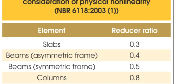
Once the building contains elements that clearly deine the hori-zontal load-bearing structure, a irst-order global analysis can be performed with the combination of increased horizontal and verti-cal loading. In considering the physiverti-cal nonlinearity of the materi -als, a stratagem is the adoption of stiffness reducer ratios for the concrete elements. Table 1 lists the values of these reducer ratios described in the NBR 6118:2003 standard [1].
According to the NBR 6118:2003 [1] (item 15.2), the second-order effects can be neglected provided they do not represent increases of more than 10% in the values of the reactions and in the impor-tant loads of the structure resulting from the irst-order analysis. This limit is the same as that prescribed by the CEB-FIP-90 code [8]. Structures with stiff nodes it these cases.
2.1.2 Instability parameter α
The irst studies that evaluated second-order effects focused only on the behavior of individual bars. Based on Eüler’s theory, Beck & König [10] developed the irst major studies involving struc-tures as a whole, working in a linear elastic regime. To this end, they considered the building as being equivalent to a single col-umn, fastened at the base and free at the top, with a constant section, and subject to a vertical load distributed uniformly along its length. Thus, the stiffness of the column was equal to the sum of the stiffnesses of the individual columns that made up the brac-ing of the structure. They then proposed a parameter (instability parameter α) which allows the structure to be classiied as having either stiff or movable nodes.
The parameter is a function of the total height of the structure, the sum of all the active vertical loads with a characteristic value, and the sum of the values of stiffness of all the columns of the building in the direction considered (for the case of column structures). For framed structures, the stiffness of each frame is considered as an equivalent column.
chitectural interests do not always meet structural require-ments adequately.
n The evolution of computational tools and methods to better evaluate accessibility, second-order loads and nonlinearity of materials.
Based on these premises, and keeping in mind that this paper fo-cuses on lat slab structures of solid reinforced concrete, the main objectives here are as follows:
a) To analyze structures in which second-order effects may be signiicant, item 15.4 of the NBR 6118:2003 standard [1] pres-ents deinitions and classiications of structures, indicating possible treatments, albeit in a simpliied way. We intend to point out possibilities and limitations for their use.
b) Evaluate the possible ways for treating building structures com-posed of beamless loor slabs in terms of their stability and the need to consider second-order effects. The inluence of beams placed only at the edges of the loor will be highlighted, since, al -though this may represent a loss of some advantages, it improves the slab’s punching performance in relation to transverse displace-ments at the edges of the slab (where they are more noticeable), and helps increase the building’s lateral load-bearing capacity. c) There are approximate considerations for the treatment of loors
designed without beams. Item 14.7.8 of the NBR 6118:2003 standard [1] foresees the possibility of designing the loor using an approximate elastic process, when the columns are placed in a regular arrangement. In these cases, and when the loors are part of the structures of multi-storey buildings, one can con -sider the formation of spatial frames composed of columns and slab bands working as lat slabs. An evaluation will be made of the ability of this structural design to behave adequately un-der horizontal loads, consiun-dering simpliications consistent with those adopted in the treatment of the loor.
d) An evaluation will also be made of the horizontal strain of these buildings and their performance in relation to the Service Limit State under horizontal loads.
2. Behavior of buildings under
lateral loads
The loading of building structures subjected to simultaneous hori-zontal and vertical forces indicates the need to analyze their global stability. The variation of the loads that appear in the structure as a result of strains caused by horizontal loads (second-order ef -fects) will depend mainly on the horizontal deformation of the struc-ture and on the magnitude of these loads. The ultimate limit state of instability in reinforced concrete structures is described by the NBR 6118:2003 standard [1] as the state that is reached when, upon increasing the load intensity, and hence the strains, some of the elements are subjected to lexural compression, and the structure’s load-bearing capacity is insuficient to bear the increased load.
2.1 Global stability of buildings:
bracing and displacement
To design high-rise slim structures subject to instabilities there are tools to for evaluating, measuring or establishing limits to the elimination of further attention. Some examples are the in -stability parameter α and the coeficient γz prescribed by the NBR 6118:2003 standard [1].
Table 1 – Inertia reducer ratios for the
consideration of physical nonlinearity
(NBR 6118:2003 [1])
Element
Reducer ratio
Slabs
0.3
Beams (asymmetric frame)
0.4
Beams (symmetric frame)
0.5
The structure is considered as having stiff nodes in the following situations:
n
1
,
0
2
,
0
+
⋅
<
a
for n ≤ 3 loors, or;6
,
0
<
a
if n≥
4 loors.The calculation and other considerations about α are given in item 15.5.2 of the NBR 6118:2003 standard [1].
2.1.3 The γz coeficient
The
g
z coeficient was created by engineers Mário Franco and Augusto Carlos de Vasconcelos (Franco & Vasconcelos [11]). This coeficient measures the sensitivity of the structure to second-order effects, i.e., to the effects of geometric nonlinearity, estimating the im-portance of second-order loads compared to that of irst-order loads. The main characteristics of the coeficient are:n It indicates if a building is a movable or stiff nodes structure, and determines if its mobility is excessive.
n It serves to estimate the ampliication of the irst-order mo -ments to consider the second-order mo-ments, without requir-ing calculation of the latter.
The condition required for the structure to be considered as having stiff nodes is for
g
z to be smaller than 1.1 (g
z < 1.1). When this oc -curs, a second-order analysis is not necessary. Item 15.5.3 of the NBR 6118:2003 standard [1] described the calculation and other con -siderations about theg
z coeficient. In the case of buildings withg
z≤
1.3, the NBR 6118:2003 standard [1] (item 15.7.2) allows an approximate analysis to consider the inal second-order loads, by increasing the hori-zontal loads of the combination considered by a factor of 0,95 •g
z.2.2 Consideration of nonlinearity
in irst-order analysis
For a simpliied analysis of cracking and physical nonlinearity of the material, the stiffnesses are reduced using the coeficients listed in Table 1. For beams, Franco [12] indicates a value of 0.5 when both sides have lexural reinforcement and of 0.4 when only one side of the tensioned beam is reinforced. For bracing composed exclusively
of beams and columns which present a value of
g
z≤
1.3, item 15.7.3 of the NBR 6118:2003 standard [1] suggests a simpliication to a single reducer ratio of 0.7 for both the beams and columns.3. Analyzed structures
3.1 Introduction
The NBR 6118:2003 code [1] presents concepts and recom -mendations to be observed in the analysis of the global stability of buildings also subject to horizontal loads. In certain cases, the approximate processes (parameter a and coeficient
g
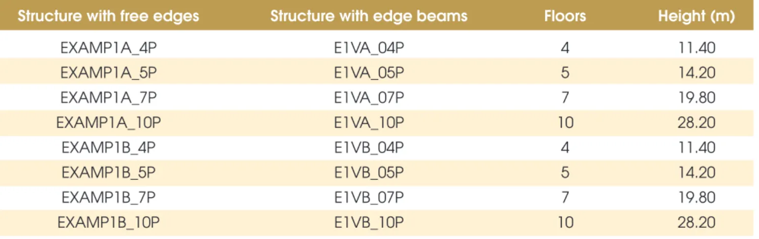
z) allow the global second-order loads to be disregarded. This is a widely ac-cepted way of evaluating the structure’s feasibility and dispenses with further calculations of its overall instability.Two types of loor plan geometry will be analyzed for the structure, each one representing buildings with four, ive, seven and ten loors. Thus, a total of eight models of different buildings will be analyzed. The instability parameter a and the coeficient
g
z will be determined for each model, according to the NBR 6118:2003 standard [1].3.2 Floors totally devoid of beams
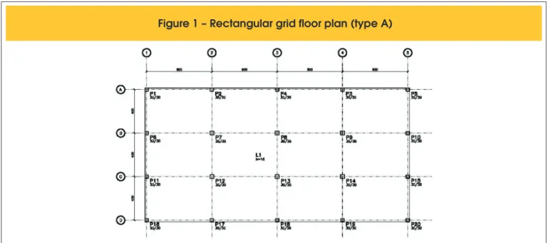
3.2.1 Floor plan geometry
in Figure 1 and is not shown here). Figueiredo [3] used these two geometries to study bending in beamless slabs, and analyze their structural performance in response to vertical loads.
3.2.2 Geometry of buildings in terms of vertical dimensions
The models consist of slabs separated by a vertical distance of 2.80 m, comprising a loor-to-ceiling height of 2.64 m. For the foundation, the distance will be considered 0.20m greater, admitting columns set in the foundation. The length of the column on the irst loor was taken
Table 2 – Heights of the structures under study; similarity between models
Structure with free edges
Structure with edge beams
Floors
Height (m)
EXAMP1A_4P
E1VA_04P
4
11.40
EXAMP1A_5P
E1VA_05P
5
14.20
EXAMP1A_7P
E1VA_07P
7
19.80
EXAMP1A_10P
E1VA_10P
10
28.20
EXAMP1B_4P
E1VB_04P
4
11.40
EXAMP1B_5P
E1VB_05P
5
14.20
EXAMP1B_7P
E1VB_07P
7
19.80
EXAMP1B_10P
E1VB_10P
10
28.20
Figure 2 – Rectangular grid floor plan (type B)
as 3.00 m. Table 2 lists the vertical characteristics of each structure.
3.3 Floors supported only by edge beams
3.3.1 Floor plan geometry
3.3.2 Geometry of the vertical dimensions
The dimensions and characteristics of buildings A and B are main-tained for cases without beams: slabs with loor to loor distance of 2.80 m. Table 2 lists the vertical characteristics of each structure (without beams and with edge beams). The roof is considered as a loor.
4. Characteristics of the materials,
loadings, modeling
4.1 Characteristics of the materials
To evaluate the models, the following values were adopted for the mechanical properties of the concrete: fck = 30 MPa;
GPa
07
,
3
f
5600
E
ci=
×
ck1/2=
;g
=
25
kN
/
m
3.In processing the frames to determine the coeficient
g
z for the ap-proximate consideration of nonlinearity physical, the values of stiff-ness of the structural elements are reduced (NBR 6118:2003 [1], item 15.7.3). In this case, the values adopted are:0
,
8
×
E
ci×
I
c for the columns, and0
,
4
×
E
ci×
I
c for the beams.The reduction of the value of the beams (40%) is justiied by the behavior of the slab bands used in the models, which is similar to that of continuous beams insofar as bending moments and rein-forcements are concerned, considering that the detailing is done following the criteria and recommendations of the simpliied model, according to item 14.7.8 of the NBR 6118:2003 [1].
4.2 Loadings considered
The loadings adopted, which are described in the items below, cor -respond to the usual values for residential building structures. The
vertical loads are in line with the NBR 6120:1980 standard [13] and the horizontal loads with NBR 6123:1988 [14]. The values adopted are the same for the two types of buildings, and also for situations with and without edge beams. The loor slabs of the ground loor and the other loors are considered identical. For the roof slabs, vertical loading is considered to be the same in all the buildings, with different values from those of the loor slabs. The values are adopted so as to resemble those of real design situations, but for the main purpose of allowing for comparisons.
4.2.1. Permanent vertical loads
The following values were adopted for loading on the normal loors for residential use (ground loor and remaining loor slabs), with the value presented in (b) corresponding to the illing, overlay and looring: a) Self weight: 4.4 kN/m2; b) Other loads: 1.1 kN/m2; c) Masonry:
1.0 kN/m2.
The value of 1.0 kN/m2 adopted for masonry (c) is based on item
2.1.2 of the NBR 6120:1980 standard, applicable to walls and room dividers (panels), whose position is not deined in the design. The loading for the roof slab remains unchanged, i.e., the value presented in (b) corresponds to the roof and overlays:
a) Self weight: 4.4 kN/m2; b) Other loads: 1.1 kN/m2.
4.2.2 Accidental vertical loads
The value of 1.5 kN/m2 was adopted for accidental loading
result-ing from use, as recommended by the NBR 6120:1980 standard [13] for most rooms in residential buildings. A value of 0.5 kN/m2
was adopted for the roof.
4.2.3 Accidental horizontal loading due to wind loads
Wind loads were determined according to the NBR 6123:1988 stan-dard [14], with the following parameters for the determination of pressure and shape coeficients:
a) Characteristic wind speed: 45 m/s. This value corresponds to the speed considered by the aforementioned standard for the region of the city of São Carlos, SP, Brazil.
b) Topographic factor S1 = 1.0, for lat or slightly irregular terrain. c) Roughness factor S2, which was determined based on the fol
-lowing data:
• Category I roughness (smooth surfaces of large dimensions); • Class B building (large plan dimensions between 20 and 50 meters);
d) Statistical factor S3 = 1.0.
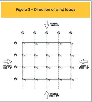
Four cases of wind load will be considered for each building, with directions in relation to the plan as illustrated in Figure 3. Cases 5, 6, 7 and 8 correspond to the calculations performed and to the results that will be discussed later herein.
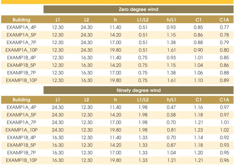
The drag coeficients were determined according to the relation -ships between the plan dimensions and the height of the various buildings. Table 3 lists these relationships and the coeficients adopted. The values correspond to parallelepipedic buildings in low turbulence regime (column C1 in the table). The C1A values shown correspond to wind in high turbulence regime. They are list-ed solely as comparative data but are not includlist-ed in the models. In the case of loors with edge beams, because the external ge-ometries are maintained, the same coeficients are valid for the
Table 3 – Drag coefficients of the buildings under analysis
Zero degree wind
Building
Building
L1
L2
h
L1/L2
h/L1
C1
C1A
EXAMP1A_4P
12.30
24.30
11.40
0.51
0.93
0.85
0.77
EXAMP1A_5P
12.30
24.30
14.20
0.51
1.15
0.86
0.78
EXAMP1A_7P
12.30
24.30
17.00
0.51
1.38
0.88
0.79
EXAMP1A_10P
12.30
24.30
19.80
0.51
1.61
0.90
0.80
EXAMP1B_4P
12.30
16.30
11.40
0.75
0.93
1.01
0.85
EXAMP1B_5P
12.30
16.30
14.20
0.75
1.15
1.04
0.86
EXAMP1B_7P
12.30
16.30
17.00
0.75
1.38
1.06
0.88
EXAMP1B_10P
12.30
16.30
19.80
0.75
1.61
1.10
0.89
Ninety degree wind
L1
L2
h
L1/L2
h/L1
C1
C1A
EXAMP1A_4P
24.30
12.30
11.40
1.98
0.47
1.16
0.97
EXAMP1A_5P
24.30
12.30
14.20
1.98
0.58
1.18
0.97
EXAMP1A_7P
24.30
12.30
17.00
1.98
0.70
1.21
1.01
EXAMP1A_10P
24.30
12.30
19.80
1.98
0.81
1.23
1.02
EXAMP1B_4P
16.30
12.30
11.40
1.33
0.70
1.14
0.92
EXAMP1B_5P
16.30
12.30
14.20
1.33
0.87
1.18
0.93
EXAMP1B_7P
16.30
12.30
17.00
1.33
1.04
1.20
0.95
EXAMP1B_10P
16.30
12.30
19.80
1.33
1.21
1.21
0.96
determination of horizontal loads. Strictly speaking, there is a slight increase in height due to the presence of the inverted beam of the roof slab. This fact was ignored in the determination of the drag coeficients, and therefore the values listed in Table 3 were main-tained in this situation, with the geometric equivalence reported in Table 2. The direction of the wind loads are those indicated in Figure 3.
4.3. Tools and methods used for structural modeling
4.3.1 Computational system
The eight models used here were created and analyzed using ver -sion 11.9.9 of the CAD/TQS systems (TQS Informática [15]). The CAD/TQS systems are tools for calculating, dimensioning, detail -ing and design-ing concrete structures. They consist of a series of subsystems for modeling buildings, with facilities for data input and construction of the structure.
To design the loor with the proposed coniguration, the most suit -able tools are those that present a solution analogous to grids or inite elements. In the case of this work, because the main purpose was the processing of frames, slab bands were deined, which
were taken as beams of little height, with the geometry proposed for the simpliied methods. The CAD/TQS systems include a three-dimensional frame system which calculates the instability coefi -cients. The frames, as well as the wind loads, are deined based on the spatial structure generated by the modeler.
4.3.2. Deinition of the geometry of the structural elements of the frames
4.3.2.1. Floors without beams
Table 4 – Dimensions of the floor beams
Type A building
bw (cm)
section
Type B building
bw (cm)
section
BEAMS
AXES
left
right
total
(cm)
BEAMS
AXES
left
right
total
(cm)
V1 = V4
A=D
15
100
115
115/16
V1 = V4
A=D
15
100
115
115/16
V2 = V3
B=C
100
100
200
200/16
V2 = V3
B=C
100
100
200
200/16
V5 = V9
1=5
15
150
165
165/16
V5 = V9
1=5
15
100
115
115/16
V6=V7=V8
2=3=4
150
150
300
300/16
V6=V7=V8
2=3=4
100
100
200
200/16
Table 5 – Dimensions of the floor beams
Type A building
b (cm)
wsection
Type B building
b (cm)
wsection
BEAMS
AXES
left
right
total
(cm)
BEAMS
AXES
left
right
total
(cm)
V1 = V4
A=D
V1 = V4
A=D
V2 = V3
B=C
V2 = V3
B=C
V5 = V9
1=5
V5 = V9
1=5
V6=V7=V8
2=3=4
V6=V7=V8
2=3=4
-
-
20
20/50
100
100
200
200/16
-
-
20
20/50
150
150
300
300/16
-
-
20
20/50
100
100
200
200/16
-
-
20
20/50
100
100
200
200/16
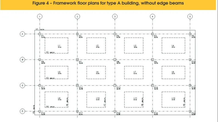
for the beams are defined as 25% of the distance to each col-umn, starting from the central line defined by the alignment of the columns. The geometry of each beam is defined by this cri-terion, and the beams’ dimensions are listed in Table 4. Figure 2 illustrates the beams listed in this table, in the case of floors on the rectangular grid.
4.3.2.2. Floors with edge beams
The frames deined to verify the stability of the eight buildings are the same, the only difference being the inverted beams at the edg-es. The section of the beams is a function of the vertical load-bear-ing capacity (20 cm × 50 cm), without considerload-bear-ing the contribution of the compression lange. The widths of the slab bands, which are admitted as internal beams, were the same as those adopted in the models without beams. The beam sections are the ones listed in Table 5. The central columns determine the dimension of bw of
the slab bands taken as beams (central bands). It should be noted that the column dimensions are unfeasible for the taller buildings.
4.3.3 Framework plans
4.3.3.1. Floors without beams
The dimensions of the type A and B buildings are listed in Table 4. Figure 4 shows the framework plan for the rectangular grid model. To simulate the behavior of the frames, leaving the beams cen-tered on the columns, the lateral beams were shifted. The values allocated automatically by the system for the beams were adjusted to prevent this artiice from resulting in higher and unrealistic val -ues of vertical loads. With regard to loading, it is important to note that the consideration made in the simpliied method, i.e., that of the loads being taken in duplicate in the beam areas, would re-sult in inadequate values of coeficients for comparison; care was therefore taken to ensure the values of the vertical loads were not considered in duplicate.
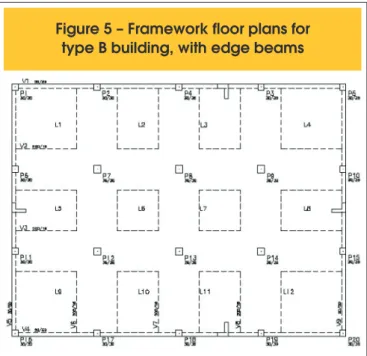
Figure 5 – Framework floor plans for
type B building, with edge beams
4.3.3.2. Floors with edge beams
The dimensions of the type A and B buildings with inverted edge beams are listed in Table 5, while Figure 5 illustrates the frame-work loor plan on the square grid. A typical detail of an edge, in el -evation, is depicted in Figure 6. The input values of the loads were designed to maintain an equivalence with the data of the previous items, to validate the comparison.
5. Results for the cases of beamless
lat-slab buildings
The results of the instability parameters a and coeficient γzof the
eight cases were presented by Cicolin [16] for ive cases of load-ing and several combinations, i.e., one case for vertical loads and four cases of horizontal loads (wind). Sixteen combinations of Ul-timate Limit State were then considered. The value of γf2 = ψ1 = 0.3
was considered for the Service Limit State, which corresponds to the frequent combination described under item 11.7 of the NBR 6118:2003 standard [1]. Section 7 summarizes the main conclusions.
6. Results for the cases of lat-slab
buildings with edge beams
This item evaluates the same structures, but with the introduction of inverted beams at the edges. This procedure should improve the performance of the frames with respect to horizontal loads, leading to smaller horizontal displacements in service. In addition, these beams facilitate the detailing by stiffening the edges and providing more eficient connections with the columns. At the edges of the slabs, which are closed with masonry, the presence of inverted beams does not represent an architectural inconvenience. Section 6.1 shows graphics of the values obtained.
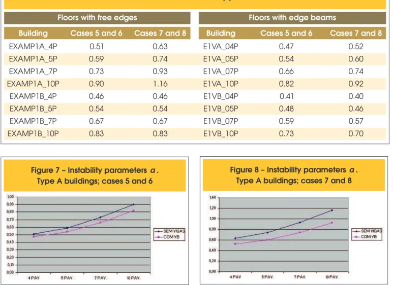
6.1 Results found for the instability parameter α
Table 6 lists the results obtained for the instability parameter α for each of the eight models, together with those of similar buildings without edge beams. The cases of loadings and combinations are the same as those of the previous item. The graphic
Table 6 – Values of the instability parameters
α
Floors with free edges
Floors with edge beams
Building
Cases 5 and 6
Cases 7 and 8
Building
Cases 5 and 6
Cases 7 and 8
EXAMP1A_4P
0.51
0.63
E1VA_04P
0.47
0.52
EXAMP1A_5P
0.59
0.74
E1VA_05P
0.54
0.60
EXAMP1A_7P
0.73
0.93
E1VA_07P
0.66
0.74
EXAMP1A_10P
0.90
1.16
E1VA_10P
0.82
0.92
EXAMP1B_4P
0.46
0.46
E1VB_04P
0.41
0.40
EXAMP1B_5P
0.54
0.54
E1VB_05P
0.48
0.46
EXAMP1B_7P
0.67
0.67
E1VB_07P
0.59
0.57
EXAMP1B_10P
0.83
0.83
E1VB_10P
0.73
0.70
tions of the values are shown in Figures 7 and 8 (type A building) and Figures 9 and 10 (type B building).
6.2 Results found for the coeficient
g
zTable 7 lists the values of
g
z, together with those obtained for the buildings without edge beams. The cases of loadings and combi-nations are the same as those used in the previous items.6.3 Maximum displacement proiles and maximum
displacements between loors
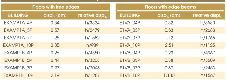
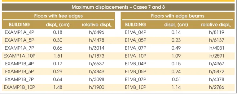
The displacements were evaluated based on the same criteria and were processed as described above. The values obtained are listed in Tables 8 and 9 (values of total displacement of each build -ing) and in Tables 10 and 11 (maximum horizontal displacement between loors).
The Service Limit State is veriied for the frequent combination, considering
g
f2 = ψ1 = 0.3.The displacements represent relative values. These values should fall within the limits mentioned earlier (h/1700 for maximum hori
-zontal displacements and hi/850 for maximum hori-zontal displace -ments between loors).
The values highlighted in bold indicate cases in which the values exceeded the permissible limit. With the presence of the beams, only the 10-loor buildings exceeded the established limit.
7. Conclusions
7.1 Initial considerations
To ensure a coherent analysis, the modeled structures should be representative of the types of buildings actually constructed; relect the behavior of usual structures; and be suficiently simple so that their behavior and results can be understood easily. Whatever the choice, there will be some degree of loss of the advantages of the intended characteristics.
It should also be kept in mind that the use of columns is consider -ably ineficient, not-ably in the case of 10-loor buildings. The sec-tions for these cases should be increased due to the vertical load. Increasing the section, and particularly, changing the inertia, so that it is used to favor the direction where the parameters proved
Figure 7 – Instability parameters
α
.
Type A buildings; cases 5 and 6
Figure 9 – Instability parameters
α
.
Type B buildings; cases 5 and 6
Figure 10 – Instability parameters
α
.
Type B buildings; cases 7 and 8
Table 7 – Values of the coefficients
γ
zFloors with free edges
Floors with edge beams
Building
Cases 5 and 6
Cases 7 and 8
Building
Cases 5 and 6
Cases 7 and 8
EXAMP1A_4P
E1VA_04P
EXAMP1A_5P
E1VA_05P
EXAMP1A_7P
E1VA_07P
EXAMP1A_10P
E1VA_10P
EXAMP1B_4P
E1VB_04P
EXAMP1B_5P
E1VB_05P
EXAMP1B_7P
E1VB_07P
EXAMP1B_10P
E1VB_10P
1.06
1.09
1.08
1.13
1.13
1.22
1.21
1.39
1.05
1.05
1.07
1.07
1.11
1.10
1.17
1.17
1.05
1.06
1.07
1.08
1.11
1.13
1.17
1.22
1.04
1.04
1.05
1.05
1.08
1.08
1.13
1.12
Table 8 – Values of maximum displacements, in cm (cases 5 and 6)
Maximum displacements – Cases 5 and 6
Floors with free edges
Floors with edge beams
BUILDING
displ (cm)
hrelative displ
hBUILDING
displ (cm)
hrelative displ
hEXAMP1A_4P
0.34
h/3334
E1VA_04P
0.32
h/3530
EXAMP1A_5P
0.57
h/2479
E1VA_05P
0.53
h/2683
EXAMP1A_7P
1.25
h/1582
E1VA_07P
1.12
h/1765
EXAMP1A_10P
2.85
h/989
E1VA_10P
2.51
h/1125
EXAMP1B_4P
0.26
h/4350
E1VB_04P
0.23
h/4967
EXAMP1B_5P
0.44
h/3208
E1VB_05P
0.38
h/3609
EXAMP1B_7P
0.97
h/2048
E1VB_07P
0.80
h/2463
Table 9 – Values of maximum displacements, in cm (cases 7 and 8)
Maximum displacements – Cases 7 and 8
Floors with free edges
Floors with edge beams
BUILDING
displ (cm)
hrelative displ
hBUILDING
displ (cm)
hrelative displ
hEXAMP1A_4P
E1VA_04P
EXAMP1A_5P
E1VA_05P
EXAMP1A_7P
E1VA_07P
EXAMP1A_10P
E1VA_10P
EXAMP1B_4P
E1VB_04P
EXAMP1B_5P
E1VB_05P
EXAMP1B_7P
E1VB_07P
EXAMP1B_10P
E1VB_10P
0.18
h/6496
0.30
h/4478
0.66
h/3014
1.51
h/1873
0.17
h/6637
0.29
h/4849
0.64
h/3098
1.48
h/1900
0.14
h/8119
0.23
h/6137
0.49
h/4031
1.09
h/2591
0.15
h/4967
0.24
h/5872
0.51
h/4378
1.14
h/2786
Table 10 – Values of maximum displacements between floors, in cm (cases 5 and 6)
Maximum displacements between floors – Cases 5 and 6
Floors with free edges
Floors with edge beams
BUILDING
displ (cm)
hrelative displ
hBUILDING
displ (cm)
hrelative displ
hEXAMP1A_4P
E1VA_04P
EXAMP1A_5P
E1VA_05P
EXAMP1A_7P
E1VA_07P
EXAMP1A_10P
E1VA_10P
EXAMP1B_4P
E1VB_04P
EXAMP1B_5P
E1VB_05P
EXAMP1B_7P
E1VB_07P
EXAMP1B_10P
E1VB_10P
0.12
hi/2418
0.17
hi/1659
0.28
hi/ 990
0.46
hi/ 604
0.09
hi/3193
0.13
hi/2146
0.22
hi/1288
0.35
hi/791
0.11
hi/2579
0.16
hi/1801
0.25
hi/1104
0.41
hi/ 685
0.08
hi/3609
0.11
hi/2518
0.18
hi/1542
0.29
hi/956
to be the most deicient, would have a positive effect on the results. In addition, it should be noted that the values considered for wind loads are higher for the national territory. Buildings erected in re-gions subject to lower winds would show a better performance.
7.2 Disregarding global second-order loads
With regard to eliminating the need to consider global sec-ond-order loads, item 15.5 of the NBR 6118:2003 standard presents two approximate processes to classify the structure as having either stiff or movable nodes; if they are stiff, no rigorous calculation is required. In the case of the structures discussed here, where the slab bands were considered as flat
beams composing frames, the limit for the structure to be con -sidered as a stiff nodes structure is α1 ≤ 0.5. On the other hand,
when the coefficient
g
z is used for the classification, its value should be lower than 1.1.The results were acceptable for some situations when the coef-icient
g
z was used. However, the existence of cases in which the value ofg
zclassiies the structure as having stiff nodes with a value of α far exceeding the limit clearly shows that the parameters are underpinned by different premises. The resulting values (α andg
z) are grouped in Table 12.Table 11 – Values of maximum displacements between floors, in cm (cases 7 and 8)
Maximum displacements between floors – Cases 7 and 8
Floors with free edges
Floors with edge beams
BUILDING
displ (cm)
hrelative displ
hBUILDING
displ (cm)
hrelative displ
hEXAMP1A_4P
E1VA_04P
EXAMP1A_5P
E1VA_05P
EXAMP1A_7P
E1VA_07P
EXAMP1A_10P
E1VA_10P
EXAMP1B_4P
E1VB_04P
EXAMP1B_5P
E1VB_05P
EXAMP1B_7P
E1VB_07P
EXAMP1B_10P
E1VB_10P
0.06
hi/4685
0.09
hi/3210
0.15
hi/1907
0.24
hi/1152
0.06
hi/4787
0.09
hi/3239
0.14
hi/1941
0.24
hi/1159
0.05
hi/5865
0.07
hi/4090
0.11
hi/2506
0.18
hi/1557
0.05
hi/5625
0.07
hi/3930
0.12
hi/2410
0.19
hi/1496
Table 12 – Comparison of parameters
a
and coefficients
g
zBuilding
Cases 5 and 6
a
g
Cases 7 and 8
a
z
g
zEXAMP1A_4P
0.51
1.06
0.63
1.09
EXAMP1A_5P
0.59
1.08
0.74
1.13
EXAMP1A_7P
0.73
1.13
0.93
1.22
EXAMP1A_10P
0.90
1.21
1.16
1.39
EXAMP1B_4P
0.46
1.05
0.46
1.05
EXAMP1B_5P
0.54
1.07
0.54
1.07
EXAMP1B_7P
0.67
1.11
0.67
1.10
EXAMP1B_10P
0.83
1.17
0.83
1.17
by the two methods, as indicated by a comparison of the numbers in Table 12. The structures indicated as having stiff nodes by the parameters α have an equivalent in γz = 1.05 (EXAMP1B_4P) or γz = 1.06 (EXAMP1A_4P – cases 5 and 6), with the latter close to the limit (α = 0.51). On the other hand, there are situations in which the value of γzindicates the structure should be classiied as hav-ing stiff nodes, while the value of α far exceeds the limit. The best example of this case is building B, with seven loors, cases 7 and 8. As for the values of the maximum displacement proile and maxi -mum displacement between loors in service, these values are higher than permissible for the higher buildings: those with 7 and 10 loors. This is consistent with the classiication of structures with movable nodes, given by the simpliied processes. Values of maxi -mum displacements between loors are also extrapolated. Further details are given in Cicolin [16].
7.3 Inluence of edge beams
The use of edge beams signiicantly improved the performance of all the structures. All the parameters evaluated (strains, instability parameter α and coeficient
g
z) presented indications of improved performance in response to the presence of inverted edge beams. In general, the values of α decreased with the introduction of edge das beams, but the taller structures are still classiied as having movable nodes. With the limit of α1 = 0.5 to consider the structureas having stiff nodes, only three of the eight models it this situa -tion: the type A building with four loors, and type B buildings with four and ive loors.
As for the coeficients
g
z, the values for the buildings with beams fall within the interval [1.05; 1.12], while the interval for the build -ings without beams is [1.06; 1.39]. Based on the criterion of the NBR 6118:2003 standard [1], the structures having stiff nodes (val -ues below 1.10), in these cases, would be type A buildings with four and ive loors, and type B buildings with four, ive and seven loors. The change in the values of γzis proportionally greater for the high-est structures. However, there are still cases in which α, with a value exceeding 0.50, indicates structures having movable nodes, while the values of γz remain below 1.10, showing a structure that could be treated according to the considerations described under item 15.7.2 of the NBR 6118:2003 standard [1].The use of edge beams reduced the values of maximum displace-ment proiles and maximum displacedisplace-ment between loors in ser -vice, and only the 10-loor buildings did not comply with the maxi-mum permissible displacements.
The introduction of edge beams is justiied, since they do not af-fect the building negatively from the architectural standpoint, nor do they make the frame construction and assembly, reinforcement and concreting phases signiicantly more dificult. Allied to these advantages, one should also consider that edge beams:
The sections used for the edge beams in the models under study could be optimized to further improve the horizontal load performance. In the case of models with 6.00 meter spans between columns, the beam sections would work more eficiently using higher inertia. How-ever, for purposes of comparison with the data of the models with free edges, the use of the 20/50 section provides an important indication. There are speciic cases in which the introduction of inverted edge beams could inluence the execution of speciic activities during the construction phase. An example of this is the case of buildings which use the solution of ready-made bathrooms. Except in special cases, this solution can be employed when one of the sides of the loor is left open to insert them into the completed structure. The edges of the loor must be lat at this location, at least until the cells speciied by the loor plan are put in place.
7.4 Final remarks
In taller building structures which use lat slabs and regularly dis-tributed columns, it should be stated only that the consideration of the frames cannot be neglected, and this may be a positive con-sideration. However, the results of high values of the parameters that measure instability, allied to the aforementioned restriction in considering the columns, does not allow for more effective conclu -sions about the use of only frames.
It should be noted that, because they present a perfect symmetry in relation to the two main axes, the cases treated here result in structures with excellent performance, avoiding the inconvenience of applying the horizontal load that, on the loor plan, falls outside the loor’s center of torsion. The use of rigid elements such as staircases usually results in structures with a negative perfor-mance with respect to this aspect.
When one considers only the numerical values, the performance in Service Limit States is a factor for concern. However, the use of columns with reduced dimensions does not allow for a deinitive conclusion.
With regard to the results of the parameters presented by the NBR 6118:2003 standard [1], the use of the coeficient γz is clearly advantageous. In only one case, with a γz value above 1.30, would it be impossible to estimate the second-order values by increasing the values. Considering that in this case the columns were used ineficiently, it can be stated that a slight improvement of the inertia of the elements would greatly increase the chances of obtaining a structure with adequate performance.
Once again, we point out that the use of edge beams resulted in a signiicant improvement of in the performance of all the structures and all the parameters evaluated (strains, instability parameter α and coeficient γz), indicating that the possibility of using edge beams
should always be evaluated, especially when they are inverted. The evolution of tools for structural analysis tends toward the treatment of three-dimensional frame structures. The complete second-order analysis of such structures, and a more precise con -sideration of nonlinearity, may improve their responses and render the use of beamless loor slab systems more competitive.
8. References
[01] ASSOCIAÇÃO BRASILEIRA DE NORMAS TÉCNICAS. Projeto de estruturas de concreto – Procedimento. NBR 6118. Rio de Janeiro, 2003.
[02] MONTOYA, P. J.; MESEGUER, A.G.; CABRÉ, F. M. Hormigón armado. 13ª. Edição. Editorial Gustavo Gili, S.A. Barcelona, 2a. tiragem. 1994.
[03] FIGUEIREDO FILHO, J. R. Sistemas estruturais de lajes sem vigas: subsídios para o projeto e execução. Tese de Doutorado. EESC-USP. São Carlos, dezembro de 1989.
[04] MELO, F. A. P.; FONTE, A. O. C.; HOROWITZ, B. Análise estrutural de lajes planas sob a ação de carregamento vertical, comparando modelos numéricos com experimentais. In: XXIX Jornadas Sudamericanas de Ingenieria Estructural, Punta Del Este, Uruguai, 2000. 15p.
[05] SILVA, L.R ; GUIMARÃES, G.N. Laje treliçada x laje cogumelo: uma análise de custo. In: 42°
CONGRESSO BRASILEIRO DO CONCRETO, Belo Horizonte MG, 2002.
[06] SYLVANY, T. T.; PINHEIRO, L. M. Deslocamentos transversais em lajes-cogumelo. Cadernos de Engenharia de Estruturas, São Carlos, 2005. 120 p. [07] LEONHARDT, F.; MÖNNIG, E. Construções de
concreto. Interciencia, Rio de Janeiro, 1978. [08] CEB-FIP Model Code 1990 – inal draft (1991).
Bulletin D’Information no 203, 204 e 205. Lausanne,
1991.
[09] FRANCO, M. Alguns problemas relativos á ação do vento em edifícios de grande altura. Tese de Doutorado. Escola Politécnica, Universidade de São Paulo, 1967.
[10] BECK, Hubert; KÖNIG, Gert. Haltekräfte im skelettbau (Forças de coninamento em estruturas de esqueleto). Beton und Stahlbetonbau 62, jan-fev 1967, pp. 7-15. Berlim, 1967. Tradução para o português do Prof. Augusto Carlos de Vasconcelos em publicação do Instituto de Engenharia.
[11] FRANCO, M.; VASCONCELOS, A. C Avaliação prática dos efeitos de segunda ordem nos edifícios de concreto armado. In Rio Coloquium on CEB-FIP Model Code 90, 1991.
[12] FRANCO, M. Problemas de estabilidade nos edifícios de concreto armado. Publicação do Instituto de Engenharia. São Paulo, 1985.
[13] ASSOCIAÇÃO BRASILEIRA DE NORMAS
TÉCNICAS. Cargas para o cálculo de estruturas de ediicações – Procedimento. NBR 6120. Rio de Janeiro, 1980.
[14] ASSOCIAÇÃO BRASILEIRA DE NORMAS
TÉCNICAS. Forças devidas ao vento em ediicações – Procedimento. NBR 6123. Rio de Janeiro, 1988. [15] TQS INFORMÁTICA LTDA. Sistemas CAD/TQS
para windows, versão 11.9.9. Manuais. São Paulo, 2004.