O. C. de Resende
EMBRAER VPI/DAP/GARThe Evolution of the Aerodynamic
Design Tools and Transport Aircraft
Wings at Embraer
This paper provides a historical summary of the aerodynamic design of transport aircraft wings during the past 35 years at Empresa Brasileira de Aeronáutica (EMBRAER) and describes, from the application standpoint, the evolution of the theoretical and experimental techniques and tools used.
Beginning with the EMB110 Bandeirante and proceeding with the EMB121 Xingu, the EMB120 Brasilia, CBA123 Vector, ERJ145 family and now with the EMBRAER 170 family, there has been a progressive shift from empirical and simplified analytical design techniques to CFD methods of ever increasing capabilities. In the experimental field, more advanced windtunnel test facilities and techniques have also been progressively employed to match the increased complexity of the computational methods.
Keywords: Aerodynamic design, aircraft wings, EMBRAER
1
Glossary
Aspect ratio = ratio between the square of the wing span and the wing area
BTWT = Boeing Transonic Wind Tunnel
CBA = Cooperação Brasil-Argentina - Brazil-Argentina Cooperation
CTA = Centro Técnico Aeroespacial - Brazilian Technical Aerospace Center
CD = Drag coefficient = D/qS CFD = Computational Fluid Dynamics CL = Lift coefficient = L/qS
CLmax = maximum lift coefficient D = aerodynamic drag force
DNW = Duits-Nederlandse Windtunnels - German-Dutch Wind Tunnels
Drag creep = slow increase in drag as the Mach number is increased, usually caused by the presence of weak shock waves
Drag rise = rapid increase in drag as the Mach number is increased, usually caused by shock-induced boundary layer separation
FAMA = Fabricaciones Argentinas de Material Aeronautico Fowler Flap = type of flap that increases the wing chord when
deflected
g = acceleration of gravity
Gap = size of the slot between the wing main element and the deflected flap or slat, usually measured in percent of the local wing chord
Induced drag = pressure drag caused by the generation of lift L = aerodynamic lift force
NACA = National Advisory Committee for Aeronautics (USA) NASA = National Air and Space Administration (USA) NLR = Nationaal Lucht- en Ruimtevaartlaboratorium - National
Aerospace Laboratory (Netherlands)
ONERA = Office National d'Etudes et de Recherches Aeroespatiales - National Office for Aerospace Research and Studies (France)
Overlap = amount of superposition (in planform view) between the flap or slat and the wing main element, usually measured in percent of the local wing chord.
Presented at ENCIT2004 – 10th Brazilian Congress of Thermal Sciences and Engineering, Nov. 29 -- Dec. 03, 2004, Rio de Janeiro, RJ, Brazil.
Technical Editor: Atila P. Silva Freire.
Parasite drag = drag due to skin friction plus pressure drag (other than induced or wave)
q = dynamic pressure = ½ρV2
RANS = Reynolds-Averaged Navier-Stokes equations S = wing reference area
Sweep angle = angle formed between a convenient spanwise wing reference line (e.g. leading edge) and an axis perpendicular to the fuselage centerline
Taper ratio = ratio between the wing tip chord to the wing root chord
TsAGI = Central Aero- and Hydrodynamics Institute (Russia) UWAL = University of Washington Aerodynamics Laboratory
(USA)
V = freestream velocity
Wave drag = pressure drag associated to the entropy generation at shock waves
ρ = air density
Introduction
The transport aircraft market, particularly the civil airliner segment, is highly competitive. Factors such as load carrying capability, performance characteristics, acquisition and maintenance costs determine the overall economic appeal of the aircraft to the market and its ultimate commercial success from the manufacturer's standpoint. Among those factors, the aircraft performance is dependent on the aerodynamic characteristics, which in turn are strongly influenced by the wing design.
This paper presents a condensed history of the aerodynamic design of transport aircraft wings during the past 35 years at Empresa Brasileira de Aeronáutica (EMBRAER), covering the aircraft that had their development completed. It also briefly describes, from the application standpoint, the evolution of the theoretical and experimental techniques and tools used. It should be noted that the aerodynamic design of an aircraft must also extend to the other components such as the fuselage, tail, nacelles and pylons. In this paper, however, only some of the major aspects related to wing design will be directly addressed.
progressively employed to match the increased complexity of the computational methods.
General Considerations in Wing Aerodynamic Design
It is not the aim of this paper to provide a full description of the aerodynamic design processes and criteria, but some considerations about this subject may be useful to give a general picture of their complexity. References 1 and 2 provide more detailed information on this subject. Transport aircraft wings are designed to meet a set of multidisciplinary technical requirements which cover aerodynamic performance, propulsion, stability and control, weight, structures, aeroelasticity, systems, production techniques, etc. In principle, all requirements are equally important and a change in any one of them (for instance, structures) could lead to significant consequences for the attainment of another (for instance, aerodynamics). Optimal overall design will always involve a compromise between these requirements. Hence, the evolution and the final aerodynamic configuration of an aircraft wing are determined by several factors, only one of which is aerodynamics itself.
With this in mind, but narrowing the discussion to aircraft performance, some typical requirements that will affect wing aerodynamics are =
- Take-off and landing field lengths - these usually constrain
the minimum wing area and the type of high lift devices (e.g. slats and flaps) employed. A larger wing area and more efficient high lift devices allow operation from smaller airports with higher payloads and more fuel.
- Cruise speed - The cruise speed requirement is associated to
the cruise aerodynamic drag. Lower cruise drag can be achieved by reducing the airfoil thickness and reducing the wing area (decreasing parasite drag) and increasing wing span (decreasing induced drag). At transonic speeds, lower drag is also achieved by increasing the wing sweep angle (decreasing wave drag). Note that some of the solutions for improving cruise speed conflict with those for minimizing field length.
- Range - Range can be increased by a combination of lower
wing drag and higher wing internal fuel volume. Note that the requirements for lower drag (smaller wing) and higher fuel volume (larger wing) are also conflicting.
- Stability and control - Stability and control requirements
place some bounds on the practical wing planform shapes. Wings with large taper ratios (small tip chord in respect to the root chord) may provide low drag with low structural weight, but could present undesirable control characteristics close to the stall. Likewise, large wing sweep angles reduce the transonic drag but could also lead to control problems at the stall.
- Aerodynamic buffet margins - Aerodynamic buffet is a low
frequency airframe vibration usually caused by shock-induced flow separation at transonic Mach numbers. Ideally, the aircraft should have sufficient margins (e.g. up to 1.3g vertical load factor) in terms of lift generating capability to be free of buffet during level flight in a turbulent atmosphere and during typical maneuvering flight. Unfortunately, the wing profile types that are less prone to buffet may have some undesirable drag creep characteristics.
In the next sections, some specific aspects of the wing design of EMBRAER aircraft and associated tools and methods will be presented.
Design and Analysis Tools for Wing Aerodynamic Design
A brief description of the aerodynamic design tools that have been used for wing design at EMBRAER, with focus on its application and usage, is given below.
Empirical/Theoretical Tools
Some of the most important theoretical tools that are in use or have been used during the design of EMBRAER transport aircraft wings are described below. They are presented in increasing order of fidelity of flow representation and, for a given level of fidelity, in increasing capability of handling complex geometry. It should be noted that, during the several phases of wing design (conceptual studies, preliminary design, detailed design), different levels of capability and 'response time' are needed. Thus, during conceptual studies, a simple empirical or 2D panel method may provide the information needed with the required accuracy, while at detailed design, a full-aircraft Navier-Stokes analysis may be necessary. So, even with the availability of more capable codes (but more costly in terms of hardware and overall response time needed to generate the grids, run and process the results), some of the older and simpler methods remain in use.
Some of the codes presented below possess an inverse design capability; that is, they can determine the geometry of the body for a given pressure distribution. Many of them have also been linked to numerical optimization routines.
Empirical Methods
Empirical methods provide very quick estimates of important design parameters early in the design process. They are based on previous aircraft data, usually from windtunnel and flight tests. The data can be interpolated using theoretically expected variations obtained from very simple physical models. Typical examples would be cruise drag and low-speed maximum lift coefficient estimates for conceptual design studies. References 3, 4 and 5 are good examples of compilations of empirical/experimental data for aerodynamic design.
2D Panel Methods (Single- and Multi-Element Airfoils)
2D panel methods are based on the Laplace equation (potential incompressible flow). When coupled with a boundary-layer code, they can be useful to predict initial flow separation. These methods can be used for preliminary low-speed airfoil design and for definition of the type of the high-lift device needed. In EMBRAER, this tool has been superseded by a 2D Euler method with coupled boundary layer, but the panel method is still used in the inverse mode to smooth the airfoil geometry.
3D Panel Methods
Figure 1. Early 3D panel method mesh (CBA123 model).
Figure 2. Early 3D panel method pressure distribution results (CBA123 model).
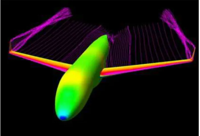
Figure 3. Up to date 3D panel method mesh (EMBRAER 170 model).
Figure 4. Up to date 3D panel method pressure distribution and wake shape results (EMBRAER 170).
2D Full Potential Methods
These methods are based on the full potential equation, which allows for flow density variations and flow discontinuities. The discontinuities (velocity and density 'jumps'), although originating from a potential (isentropic and irrotational) equation, can be associated for practical engineering purposes with shock waves and the associated wave drag. These methods are used for transonic airfoil design. They are usually coupled with a boundary layer code, since fairly small airfoil 'effective geometry' changes (caused by the boundary layer displacement thickness) can lead to fairly large changes in the flow (surface pressure distributions) at transonic speeds. In EMBRAER, this tool has also been superseded by a 2D Euler method with coupled boundary layer. Reference 7 provides more information on the full potential method.
3D Full Potential Methods (Wing Alone)
Transonic wings are usually swept back to reduce the effective Mach number normal to leading edge, resulting in lower wave drag. Although simple 'effective' Mach number corrections are still used for preliminary 2D airfoil design, the non-linear nature of transonic flow and the swept wing self-induced upwash along its span require a 3D method for more refined analyses. EMBRAER used an inviscid wing-alone full-potential method to design some of its aircraft, but this has been superseded by a wing-fuselage full potential method with boundary layer correction.
3D Full Potential Methods (Wing Plus Fuselage)
Besides the self-induced upwash, wings are strongly influenced by the presence of the fuselage and the boundary layer. EMBRAER currently employs a full potential wing plus fuselage method with coupled boundary layer to design transonic transport wings. The boundary layer equations are solved by a finite-difference 3D method that provides the increased fidelity necessary for transonic design. This method can also be coupled with an inverse design module.
2D Euler Methods (Single- and Multi-Element Airfoils)
The Euler equations, as opposed to the full potential equation, can properly handle strong flow discontinuities (shocks). In this manner, they provide more precise results when local supersonic regions attain higher Mach numbers within the transonic flow. Additionally, although the Euler equations are inviscid, the artificial viscosity in the numerical method represents quite well the wake of the airfoil. This is specially useful when a multi-element airfoil is analysed, as the method will automatically compute physically meaningful wake shapes for each element as part of the solution. In a potential method, the wake shapes would have to be prescribed in the input or be obtained by an iterative solution. The 2D Euler method is used by EMBRAER for transonic single element airfoil and for low-speed multi-element airfoil analysis and design. The method is coupled with a 2D integral boundary layer code.
3D Euler Methods, 2D Stokes (RANS), 3D
Navier-Stokes (RANS)
suitable computational grids and solving the equations themselves. If viscous phenomena are not important for a particular case, the viscosity can be set to zero and an Euler analysis can be performed on a coarser grid in a considerably reduced time.
EMBRAER employs a 2D/3D RANS/Euler code for detailed analyses of complex geometric configurations such as wing plus pylons and nacelles. Figures 5a and 5b present an example of this application. Transonic winglet design is also performed with the 3D Euler and N-S code. 2D analyses are also performed for airfoils in situations where large separated regions are present, such as an airfoil with a deployed spoiler.
Figure 5a. CFD pressure distribution results for wing-pylon-nacelle configuration (EMBRAER 170)Initial configuration with wing upper surface shock caused by pylon-wing interference.
Figure 5b. CFD pressure distribution results for wing-pylon-nacelle configuration (EMBRAER 170)Refined configuration with pylon-wing interference shock eliminated.
Euler and Navier-Stokes formulations are continuously being developed and refined for many applications. Reference 8 provides a detailed introduction to the subject.
Experimental Tools
In spite of the large advances in CFD in the past 30 years or more, the windtunnel remains a very important tool for aircraft development. The overall time cycle for a complete windtunnel test campaign is long, typically including from 3 to 6 months for model design and construction, from 1 week to 2 months for testing and from 1 week to 3 months for analysis of the results. However, once the model is in the tunnel and the test is under way, a huge amount of very precise data can be generated very quickly, far exceeding the current combination of speed and precision of CFD methods.
While CFD can provide qualitative results that can be used for wing design optimization, up to now only the windtunnel can provide reliable absolute values for many aerodynamic parameters. In other words, CFD plus an optimization procedure can reliably find a minimum or a maximum even if its absolute is not known
precisely, while the windtunnel can provide a more precise absolute value. Both types of information (minima/maxima and absolutes) are needed for a successful wing design.
It should be noted that many types and subtypes of tunnels exist with varying degrees of size, speed capability and usage cost. The following paragraphs describe only some types of tunnel that have been used by EMBRAER for transport wing design.
Subsonic constant total pressure windtunnels are one of the
most traditional types of tunnel in use around the world. They operate close to the ambient atmospheric pressure, which usually means that the test Reynolds number is much smaller than full scale. This imposes some limitations on the types of test that can be performed and requires theoretical or empirical corrections to the results. However, they are comparatively inexpensive to operate and can still provide very useful information during all phases of the aerodynamic wing design. This type of tunnel has been used in at least one phase of the design of every EMBRAER transport aircraft that reached production status. The TA-2 at CTA in São José dos Campos (figure 6) and the UWAL at the University of Washington in Seattle, USA (figure 7) are typical examples that have been used by EMBRAER.
Figure 6. Subsonic constant total pressure tunnel test - EMB120 Surface oil flow visualization at CTA.
Figure 7. Subsonic constant total pressure tunnel - ERJ145 at UWAL.
Subsonic pressurized windtunnels can control the pressure
process of pressurizing the tunnel, running the test and depressurizing it to allow model configuration changes makes it more time consuming and costlier than a subsonic atmospheric tunnel. However, the test results are usually much more precise and closer to the full scale values. This type of tunnel has been used by EMBRAER during the 170 design. The ONERA F1 at Toulouse/Mauzac in France (figures 8 and 9) is an example of subsonic pressurized windtunnel.
Figure 8. Subsonic pressurized tunnel test - EMBRAER 170 half model at ONERA F1.
Figure 9. Subsonic pressurized tunnel test - EMBRAER 170 full model at ONERA F1.
Transonic constant total pressure windtunnels are, as
the name implies, capable of reaching speeds corresponding
to
Mach numbers close to unity. In a constant total pressure transonic tunnel, the Reynolds number increases as the Mach number is increased. This adds additional effects that need to be compensated for during the analysis of the results, as Mach and Reynolds effects are mixed in. This type of tunnel was used during the development of the ERJ145. The BTWT (Boeing Transonic Wind Tunnel) at Seattle, USA is an example of transonic constant total pressure windtunnel.Transonic pressurized windtunnels are capable of changing
Mach numbers at constant Reynolds numbers. The pressurization and density are progressively decreased as the Mach number is increased in order to keep Reynolds constant. The Reynolds number can usually be kept higher than would be possible with an
atmospheric tunnel, minimizing the necessary theoretical corrections to the results. Transonic pressurized windtunnels have been used by EMBRAER since the EMBRAER 170. Examples of transonic pressurized windtunnels are the DNW/HST in Amsterdam, Netherlands (figures 10 and 11) and the TsAGI T-128 in Moscow, Russia.
Figure 10. Transonic pressurized tunnel test - EMBRAER 170 at DNW/HST.
Figure 11. Transonic pressurized tunnel test - EMBRAER 170 at DNW/HST - Front View.
A Brief History of EMBRAER Transport Aircraft and
the Evolution of Their Wing Design
Table 1. Summary of EMBRAER transport aircraft wing aerodynamic configurations and associated design tolls.
Aircraft Cruise Wing High Lift Devices Theoretical Methods Windtunnel Tests
Leading Edge Trailing Edge
EMB-110 Bandeirante Straight-tapered unswept wing, NACA 5-series profiles 23016 root, 23012 tip
None
Double slotted flap, fixed vane, circular arc kinematics with external support brackets
Empirical Low-speed testing at
CTA and in France
EMV-121 Xingu
Same wing as the EMB 110, with reduced span
None
Double slotted flap, fixed vane, circular arc kinematics with internal tracks
Empirical Low-speed testing at
CTA EMB-120 Brasília Straight-tapered unswept wing, NACA 5-series profiles 23016 modified at root, 23012 tip
None
Double slotted Fowler flap, fixed vane, moveable lower shroud, internal tracks
Empirical, Lifting line, 2D panel method to improve root profile CLmax characteristics
Extensive low-speed windtunnel test campaign (CTA).
2D profile+flap and 3D full aircraft tests. Hinge moment tests for ailerons
CBA-123 Vector
Compound taper, unswept wing with advanced profiles based on NASA MS-series
None
Double slotted Fowler flap, fixed vane, moveable lower shroud?, internal tracks
2D panel method coupled with optimization procedure for cruise. 2D multi-element panel method for flap design. Transonic 2D profile design using linearized
Extensive low-speed windtunnel test campaign (CTA) and Argentina 2D profile+flap and 3D full aircraft windtunnel tests. First transonic windtunnel test campaign (BTWT) for an EMB aircraft ERJ-145 with overwing engines Straight-tapered unswept wing, modified in chord and pan in respect to the EMB 120 wing
None
Double slotted Fowler flap, fixed vane, moveable lower shroud, internal tracks
2D multi-element panel method flap design. Transonic 2D profile analysis and design using linearized full potential wing design method. 3D panel method for wing-nacelle-fuselage interference analysis
Low-speed windtunnel testing at CTA. Transonic testing at BTWT with blown nacelles ERJ-145 with underwing engines Compund taper, swept wing wit transonic airfoils designed by EMB
None
Double slotted Fowler flap, fixed vane, moveable lower shroud, internal tracks
2D multi-element panel method for flap design .Transonic 2D profile analysis and deign using linearied full potential equation wit Cartesian coordinates. 3D full potential wing analysis method. 3D panel method for pylon/nacelle design
Low-speed windtunnel testing at CTA. Transonic testing at BTWT
ERJ-145 with rear fuselage engines
Compound taper, swept wing with transonic airfoils designed by EMB. Winglets present in some derivatives
Fixed leading edge droop
Double slotted Fowler flap, fixed vane, moveable lower shroud, internal tracks
2D multi-element panel method for flap design. Transonic 2D profile analysis and design using linearized full potential equation with Cartesian coordinates. 3D full potential wing analysis method. 3D panel method for pylon/nacelle. 3D Euler / NS solver for winglet design
Low-speed windtunnel at CTA and UWAL. Transonic testing at BTWT. Hinge moment tests?
EMB 170/175
Compound taper, swept wing with transonic airfoils designed by EMB. Winglets
Slats
Double slotted Fowler flaps with moveable main and aft elements. External supports
2D multi-element Euler method with coupled boundary layer for transonic profile and high lift device analysis and design. 3D full potential wing analysis method. 3D panel method for pylon/nacelle design, slat and flap detailed design. 3D Euler / NS solver for wing-pylon-nacelle analysis and winglet design
EMB110 Bandeirante
The Bandeirante is a non-pressurized twin turboprop aircraft with a 15-19 passenger capacity (figure 12). The design of the Bandeirante began as the IPD/PAR 6504 project during the late 1960's at CTA (Centro Técnico Aeroespacial) of the Brazilian Ministry of Aeronautics, to provide the Brazilian Air Force with a light transport aircraft to replace obsolescent aircraft then in service. The prototype first flight occurred in 1968. The project was transferred to EMBRAER when the company was founded in 1969 and the first delivery of the initial production version was in 1972. Production ended after almost 500 aircraft had been delivered to several military and civilian customers around the world. The type remains in service in Brazil and abroad.
Figure 12. EMB110 Bandeirante.
The EMB110 has straight tapered unswept wings. The wing profiles were selected from the NACA 5-series family with 16% relative thickness at the root and 12% thickness at the tip. No geometric twist was employed. The high lift devices consist of double slotted, fixed vane flaps that extend in a circular arc motion supported by external scissors. The wing aerodynamic characteristics were evaluated by empirical methods and were later validated and refined through low-speed, low-Reynolds windtunnel testing performed in France (prototype) and in CTA (series production version).
EMB121 Xingu
The Xingu is a pressurized twin turboprop aircraft with a 5-9 passenger capacity (figure 13). First flight occurred in 1976 and production amounted to around 100 aircraft. The aircraft remains in service with civilian (business / executive) and military operators (Brazilian and French Air Forces and French Navy). The Xingu was intended to be the first and smallest member of a family of aircraft with up to 25-30 passengers, to be achieved through progressive fuselage stretches and a new wing. However, market analysis indicated that a larger fuselage diameter would be necessary for a 30 seat aircraft, which led to the EMB120 Brasilia.
Figure 13. EMB121 Xingu.
The aircraft uses the Bandeirante wings with clipped tips mated to a new fuselage and tail surfaces. To reduce drag in cruise, the flap support scissors were replaced by internal tracks at the inboard and outboard flap ends.
EMB120 Brasilia
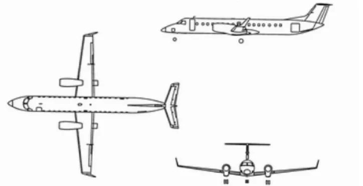
The Brasilia is a twin turboprop with a 30 passenger capacity (figure 14), designed to meet primarily the regional aircraft markets of the USA and Europe in the early 1980's. The design began in the late 1970´s and the first flight was performed in 1983. Initial deliveries were made in 1985. Around 350 aircraft have been produced and the type remains in service around the world.
Figure 14 .EMB120 Brasilia.
The EMB120 has unswept wings without geometric twist. The absence of twist allowed for some simplification in the structural design and production methods with very small penalties in induced drag due to the fairly high aspect ratio and relatively low wing loading. Additionally, the absence of twist had little practical effect on maximum lift capability, since propeller slipstream and torque effects defined the limiting stall characteristics. As is typical in many commercial transports, good stall characteristics are guaranteed by artificial means such as stick shaker and stick pusher systems.
fairly narrow channel between fuselage and nacelle produced premature flow separation at high angles of attack, reducing the maximum lift coefficient. The root airfoil was then modified by a leading edge extension that reduced the local relative thickness to 16% without changing the front wing spar position and the wing torsion box. With this modification, the wing acquired a subtle compound taper. The inboard panel leading edge was defined by a line that ran from wing root to the station with 16% relative thickness on the original wing. This inboard taper, however, extended only from the fuselage to the nacelle. The wing outboard of the nacelle remained unchanged. The root profile modification was analysed and validated by a 2D panel method, probably the first time such a method was used in an EMBRAER design.
The flaps are of fixed vane, double slotted Fowler type, supported at their ends by internal tracks. On the lower surface of the rear part of the wing torsion box there is a moveable shroud that moves up when the flaps are extended, preventing flow separation on the gap between wing and flap and improving maximum lift. Extensive low-speed windtunnel test campaigns were performed at CTA during the EMB120 design.
During the prototype flight tests, some regions of flow separation were noticed in the partially deflected ailerons during climbs simulating the loss of one engine with take-off flaps deployed. To avoid the increased drag associated with the separated flow, a small wing fence was placed between flap and aileron, and a row of vortex generators were placed along the span in front of the ailerons.
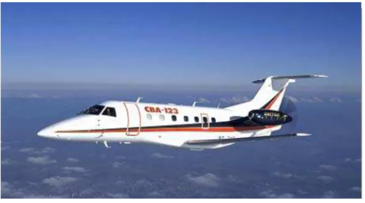
CBA123 Vector
The CBA123 was conceived as an advanced pressurized twin turboprop for 19 passengers (figure 15). It used the same nose and cross-section of the EMB120 Brasilia, but with a shorter center fuselage plus a new rear fuselage and tail. The engine nacelles with pusher propellers were mounted on pylons on the rear fuselage. The innovative configuration (for a turboprop aircraft) would offer higher speeds and levels of comfort when compared to existing aircraft of the same capacity. The aircraft was developed together with Argentina´s FAMA and reached the flight test stage, with two prototypes being flown during 1989-1990. Ultimately, the market foreseen for the aircraft (higher speed and comfort, but associated with increased cost and passenger fares) did not materialize and the aircraft did not go into production. However, many production techniques and the engineering know-how developed for the CBA123 were later used during the ERJ145 design.
Several interesting problems and solutions to the aerodynamic integration of the engines and pusher propellers to the fuselage were found during its development, but these are unfortunately outside the scope of this paper. However, one of the indirect consequences of the engine position was the need for a compound wing taper, dictated by the need to retract the landing gear legs into the inboard wing. To minimize cruise drag, the wing area was fairly small and the aspect ratio was large. The small wing area required more advanced profiles to provide higher lift coefficients with and without flaps extended. The profiles were modified and optimized at EMBRAER from the new NASA MS-03XX (Medium Speed) profiles, using a 2D panel method coupled with an optimization routine. This was the first application of a numerical aerodynamic optimization technique to an EMBRAER aircraft. These profiles attained high maximum lift coefficients through the use of fairly thick and rounded leading edges and a larger amount of camber at the trailing edge when compared to 'conventional' NACA 5 or 6-series airfoils. A 3D panel method was used to optimize wing twist for low overall drag at high subsonic speeds. Also for the first time, the flaps were designed using a multi-element 2D panel code. The
flaps were divided in 3 panels per each semi-wing to allow for adequate lateral control in the event of failure or asymmetric deployment of any of the panels (a certification requirement). The flaps, following the experience of previous EMBRAER aircraft, were of the double slotted, fixed vane type with internal tracks.
Figure 15. CBA123 Vector.
The CBA123 was the first EMBRAER design to be tested in a transonic windtunnel, besides the usual low-speed windtunnel tests at CTA and Argentina. Although the aircraft normal cruise (up to Mach=0.58) was fast for a turboprop, it did not quite reach the transonic regime. However, certification requirements asked for demonstration of adequate aerodynamic characteristics at speeds up to Mach=0.65, which would cause supersonic flow regions to appear on the wing upper surface. The tests were performed at the Boeing Transonic Windtunnel (BTWT) facility in Seattle, USA. The results showed that no stability and control problems would appear within the extended flight envelope up to Mach=0.65.
During initial flight tests, it was noticed that the aerodynamically balanced, manually actuated ailerons were floating up symmetrically at cruise conditions. This was caused by the increased amount of camber designed into the airfoil trailing edge, which produced increased rear aerodynamic loading and tended to push the aileron trailing edges upwards. The problem was solved by rigging the ailerons symmetrically with a nominal 'trailing edge down' deflection, calculated to cancel out the effect of the rear loading in flight. Additionally, the lower surface of the aileron trailing edge was modified to decrease the amount of rear camber.
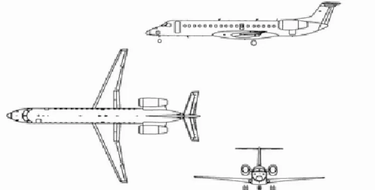
ERJ145
Figure 16. ERJ145.
Three major different aerodynamic configurations were extensively studied during the ERJ145 development = straight wing with overwing mounted engines, swept wing with underwing mounted engines and swept wing with rear fuselage mounted engines. The last configuration was the one chosen for production.
The initial configuration was directly derived from the EMB120 and had the turbofan engines mounted over the wings approximately at the same position of the original turboprops (figure 17). The center fuselage was stretched to carry 45 passengers, thus resulting in the original EMB145 designation. The straight tapered unswept wing was derived from the Brasilia's. The wing rear part was kept, including the original rear and front spars, but the entire leading edge was extended to reduce the airfoil maximum relative thickness from 16% to 14% at the root and from 12% to 10% at the tip. An additional front spar was also introduced, the wing span was increased and winglets were installed. Initially, the design cruise Mach number was M=0.70, but during development it was raised to M=0.75 to provide a cruise performance differential in respect to that of competing new generation turboprops. The advantages of the configuration would be its low development and production costs (using modified Brasilia tooling and jigs), superior performance and comfort in respect to turboprops and reduced acquisition and operating costs in respect to other regional jets then in development. However, transonic windtunnel tests indicated higher than expected drag at M=0.75 and the modified wing was also found to be heavier than originally estimated. The aerodynamic analysis and design tools available at the time in EMBRAER (1989 - full potential 2D airfoil code with coupled boundary layer, 3D inviscid wing full potential code and a 3D panel method) were not capable of calculating the unfavorable aerodynamic interference between the jet exhaust and the supersonic flow on the wing upper surface. Although there was prior qualitative knowledge of the phenomenon and the associated risks, it took a transonic windtunnel test at BTWT to confirm the problem, leading to the abandonment of the configuration.
Figure 17. ERJ145 - Over wing mounted engines configuration.
The second configuration had an entirely new wing with approximately 26 degrees of leading edge sweep. The engines were mounted in pylons under the wings, requiring taller landing gears (figure 18). The fuselage was stretched to carry 48 passengers and the nose was extended to accommodate the longer landing gear leg. The design cruise Mach number was raised to around M=0.80 to 0.82. The wing was designed using the available full potential transonic 2D and 3D codes. The resulting transonic airfoils had moderate rear loading, being of the type commonly called 'supercritical' due to the large region (typically from 10% to 70% chord) of supersonic flow on their upper surface at cruise conditions. This type of airfoil has been used in transonic transport aircraft since the late 1970's/early 1980's. Low transonic drag is obtained by keeping the flow on its upper surface at low supersonic Mach numbers, avoiding the presence of strong shock waves that could cause boundary layer separation. However, these low supersonic Mach numbers on the 'supercritical' region do not allow very large pressure differences to be generated between the upper and lower airfoil surfaces, resulting in reduced local lift. The required additional lift is achieved by increasing the camber at the rear part of the airfoil. The resulting wing profile shape is fairly flat on the upper surface from 10% to 60 or 70% of the chord, curving downward from that point until the trailing edge. In the lower surface, a concave region is present in the rear 30% to 40% of the chord. Figures 19 and 20 show the typical geometric and pressure distribution differences between a 'conventional' and a 'supercritical' airfoil. In the case of the ERJ145, aileron upfloat caused by the increased rear loading would not occur because the ailerons were hydraulically powered.
Figure 19. Typical pressure distributions - Conventional and supercritical airfoils.
Figure 20. Typical geometry - Conventional and supercritical airfoils.
The pylon and underwing engine installation were evaluated using a 3D panel code which, in spite of being formally incapable of handling transonic problems, gave useful qualitative subsonic design indications. The configuration was successfully tested in the transonic Boeing Transonic Windtunnel and met the performance expectations. Although the aerodynamic configuration was successful, the problems associated with the longer landing gear proved harder to solve. The cost of the fuselage nose modification would have been high, the longer landing gears would have required the installation of emergency escape slides, leading to the loss of space for two passenger seats and the close proximity of the engines to the ground would still have posed considerable risks of foreign object ingestion and damage. All these problems caused the underwing engine configuration to be abandoned.
The third major aerodynamic configuration had the engines mounted on pylons on the rear fuselage (figure 21). There was a further increase in fuselage length to accommodate 50 passengers and the wing was initially the same as that of the underwing configuration. This configuration, with the changes described below, was the one finally chosen for production.
The ERJ145 uses fixed vane double slotted Fowler flaps. A moveable lower surface shroud, similar to the one in the EMB120, is also employed. Although good transonic windtunnel results had been obtained for the cruise wing at the Boeing Transonic Windtunnel, low speed windtunnel tests at CTA indicated that the maximum lift coefficient values would not meet the short take-off and landing field lengths required for regional airline operations. At about the same time, market surveys indicated that the potential clients would not require cruise speeds in excess of Mach 0.75 to 0.78. This provided design margins to allow the leading edge to be modified with a fixed 'droop' and the wing root flap chord to be extended by 0.15 m. The droop was designed using the 2D and 3D full potential methods. Additionally, four vortilons were installed on the lower surface leading edge of the outboard wing panel. Their
interaction with the wing sidewash at high angles of attack produce strong vortices that are convected to the upper surface, where they modify the pressure distribution and boundary layer development, postponing flow separation and increasing maximum lift. Their shape and position were defined using the 3D panel program. The combined effect of the leading edge droop and vortilons allowed an improved take-off and landing performance without resorting to more complex variable geometry leading edge devices (such as slats), for a small cruise performance penalty. Figure 22 shows a schematic representation of the ERJ145 droop and vortilon.
Figure 21. ERJ145 - Rear fuselage mounted engines configuration.
Figure 22. ERJ145 leading edge droop and vortilons.
EMBRAER 170 Family
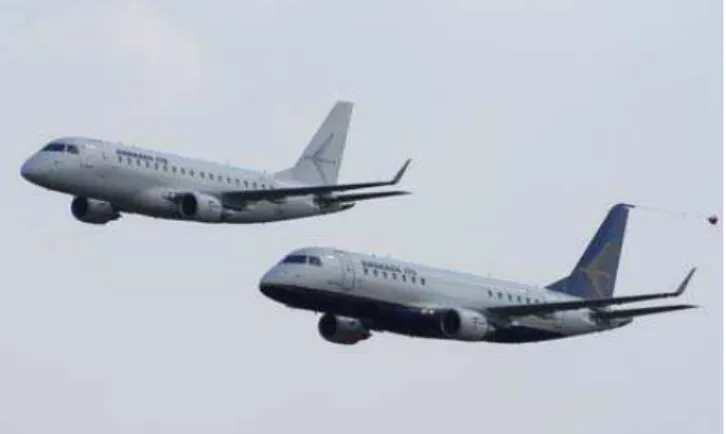
The EMBRAER 170 / 175 family is composed by twin turbofan aircraft with a 70 to 86 passenger capacity (figure 23). The design originated primarily from the growth of the regional jet aircraft market, which had been served by either current aircraft of up to 50 seats or older generation larger aircraft. The 170 family was designed to offer passenger comfort levels equal to or superior to the those of the existing regional and mainline aircraft, combined with low operating costs. This has been achieved by the combination of advanced design features such as wide double-bubble fuselage cross-section with 4-abreast seats, a fly-by-wire control system coupled with advanced design techniques in aerodynamics, structures and avionics.
Figure 23. EMBRAER 170 and 175.
The EMBRAER 170 (70 to 78 seats) design was initiated in 1999 and first flight occurred in 2002. First deliveries occurred in 2004. The EMBRAER 175 (78 to 86 seats) was derived from the EMBRAER 170 by a stretch in the fuselage. Currently there are more 100 firm orders and more than 150 purchase options for the EMBRAER 170 family.
The EMBRAER 170 wing design was driven by the need to obtain fairly high maximum cruise Mach numbers (0.78-0.82) associated with very good take-off and landing performance. The short field requirements led the high lift device design to double slotted Fowler flaps with moveable main/aft elements and slats. This was the first time that this aerodynamically efficient but structurally complex combination was used on an EMBRAER transport aircraft. The initial slat design consisted of four panels (one inboard of the pylon, three outboard) supported by circular arc tracks of varying (conical) radius along the span. It provided a constant gap and overlap along the span for the take-off and landing slat deflections. The take-off position would have a gap close to zero to minimize drag, while the larger gap/overlap at landing position would maximize lift. However, support tracks with constant radius along the span were eventually chosen to achieve lower production costs at the expense of some small increase in take-off drag. Landing performance was not affected. Two spanwise flap panels are used (inboard and outboard of the wing planform taper break) and both deflect parallel to the flight direction, supported by external tracks and carriages. A 2D Euler method and a new 3D panel method, both coupled to boundary layer codes, were used for slat and flap design. Due to the ambitious maximum lift coefficient requirements and the larger size of the 170 when compared to previous EMBRAER aircraft, the traditional low speed constant pressure windtunnel tests were not capable of providing accurate results. The tunnel test Reynolds number, based on the reference chord length, would be around 1.0 x 10⁶ for a typical model while full scale Reynolds would be around ten times that value. The empirical Reynolds
extrapolations for maximum lift and other coefficients would not provide reliable results for such a wide range of values. It was decided then to build a half-model (divided at the fuselage symmetry plane) of 1/5 scale and test it at a pressurized windtunnel. Although the half model would only provide longitudinal aerodynamic coefficients (zero sideslip angle), the large model scale, coupled with the increased air density of the pressurized tunnel, would provide Reynolds numbers equal to those of full scale. The tests were performed at the ONERA F1 facility close to Toulouse/Mauzac in France. Test runs were done at several different Reynolds numbers varying from 1.0 x 10⁶ to full scale, which allowed empirical correlations between maximum lift coefficient versus Reynolds to be obtained. These were used to determine the minimum test Reynolds number necessary to achieve reliable extrapolation to full scale. This information was later used during the 175 windtunnel test campaigns, which were performed using full (as opposed to half-) models at intermediate Reynolds numbers. Figures 8 and 9 present the 170 half and full models in the ONERA F1 tunnel.
The 170 cruise configuration airfoils were designed using a 2D Euler code with boundary layer correction and the wing was designed using a inviscid 3D full potential code. Even though the wing had slats for take-off and landing, certification requirements placed some constraints on the minimum value for the CLmax in cruise configuration. Some additional camber was added to the wing leading edge to meet the target cruise CLmax. The airfoils are of supercritical 'standard rooftop' type, in which a supersonic, fairly constant pressure plateau exists on the top surface at the cruise design condition. The cruise configuration was tested in the DNW/HST (NLR) transonic pressurized windtunnel at Amsterdam in the Netherlands. This allowed the Mach effects to be obtained at constant Reynolds number, which helped considerably in the analysis of the results. Figures 10 and 11 show the 170 transonic model in the DNW/HST tunnel. The 170 also marked the first time a 3D Euler / NS code was used in an EMBRAER aircraft, during the wing-pylon-nacelle interference studies and for winglet design. Figures 5a and 5b show an example of the refinement to the wing-pylon-nacelle configuration to minimize adverse aerodynamic interference with the wing. The CFD results were validated using a transonic half model with model turbines driven by compressed air (TPS - Turbine Powered Simulator) at DNW/HST. Winglets were designed using the 3D Euler/NS method with particular attention to the aerodynamic interference effects at the wing to winglet junction. They helped to improve the cruise and take-off performance. The final wing overall design met or exceed the performance requirements.
Conclusion
In a highly competitive environment such as that for commercial transport aircraft, the aerodynamic design methods and tools must undergo continuous updating and improvement. There is, however, a permanent need for tools of all levels of complexity and response time. What we probably shall see in the future is the substitution of simpler, more primitive tools by newer and more capable ones with the same or better response times. It should be stressed that the physical understanding of the underlying physical phenomena must remain clear to the user. In this aspect, the simpler tools might still be around to provide for this need.
The progress that has been made in the past 35 years will certainly continue and benefit future products. The 190/195 belong to the newest family of EMBRAER aircraft, still in their final phase of development (and thus unfortunately beyond the scope of this work). However, they will certainly have reaped many benefits in this field from previous EMBRAER programs.
Acknowledgements
The author would like to thank the ABCM and the ENCIT2004 Organizing Committee for the kind invitation for writing this paper. The author would also like to acknowledge and thank several colleagues from EMBRAER that took part in the development of many of the aircraft mentioned in the text and provided help during the preparation of this work. Special mention should be made to Mr. José Renato de O. Melo, Mr. Decio C. Pullin, Mr. René Landman and Mr. Marcelo Curvo, Mr. Luiz Fernando T. de Oliveira, Prof. Durval H. da Silva Filho and Mr. Renzo G. Fernandes who provided valuable information about the EMBRAER aircraft through their comments and suggestions. Mr. Paulo Komatsu, Mr. André Martins, Mr. Marcello Areal and Mr. Alexandre P. Antunes
provided figures and complementary information on the methods and tools employed for aerodynamic design. Finally, any eventual omissions and errors in this work are entirely on the author's account.
References
Torenbeek, E., "Synthesis of Subsonic Airplane Design", Delft University Press, Martinus Nijhoff Publishers, 3rd Edition, 1986
Roskan, J., "Airplane Design Part I - Preliminary Sizing of Airplanes", DAR Corporation, Lawrence KS, USA, 1985
Abbott, I. & Doenhoff, A., "Theory of Wing Sections", Dover Publications, New York, 1959
Engineering Sciences Data Unit - ESDU International plc, London DATCOM - USAF Stability and Control Data Compendium
Katz, J. & Plotkin, A. " Low-Speed Aerodynamics = From Wing Theory to Panel Methods", McGraw-Hill, 1991
Nixon, D., “Transonic Aerodynamics”, Martin Summerfield Series Edition, New York, USA, 1981
Hirsch, C., "Numerical Computation of Internal and External Flows, Computational Methods for