Abstract
Fuel consumption and safety are currently key aspects in automo-bile design. The foam-filled thin-walled aluminium tube represents a potentially effective material for use in the automotive industry, due to its energy absorption capability and light weight. Multi-objective crashworthiness design optimization for foam-filled dou-ble cylindrical tubes is presented in this paper. The doudou-ble struc-tures are impacted by a rigid wall simulating quasi-static and dynamic loadings. The optimal parameters under consideration are the minimum peak crushing force and maximum specific energy absorption, using the non-dominated sorting genetic algorithm-II (NSGA-II) technique. Radial basis functions (RBF) and D-Optimal are adopted to determine the more complex crashworthi-ness functional objectives. The comparison is performed by finite element analysis of the impact crashworthiness characteristics in tubes under static and dynamic loads. Finally, the optimum crashworthiness performance of empty and foam-filled double tubes is investigated and compared to the traditional single foam-filled tube. The results indicate that the foam-foam-filled double alumin-ium circular tube can be recommended for crashworthy structures.
Keywords
Crashworthiness; cylindrical tube; optimization; axial impact; NSGA-II.
Multi objective optimization of foam-filled circular tubes for
quasi-static and dynamic responses
1 INTRODUCTION
Consumers’ growing awareness of safety and fuel-efficiency has led the automotive industry to increase crashworthiness and decrease the weight of vehicles. The major challenge to achieve such targets has been to identify new materials and redesign structures. Simulation methods have been adopted because physical crash testing is costly. They allow the investigation of the behaviour of thin-walled tubes and to improve the energy absorption of materials by considering various pa-rameters, including geometry, size, cross-section, and loading conditions refer to book as Jones
Fauzan Djamaluddina Shahrum Abdullahb Ahmad K. Ariffinc Zulkifli M. Nopiahd
Department of Mechanical and Materials Engineering, Universiti Kebangsaan Malaysia of Malaysia
Corresponding author:
a[email protected] b[email protected] c[email protected] d[email protected]
http://dx.doi.org/10.1590/1679-78251638
(1989) and the article of Lu and Yu (2003). In the case of thin-walled circular tubes under axial impact, energy absorption behaviour has been studied by several scholars such as Reid (1993); Alghamdi (2001); Alexander (1960). The dynamic instability of different tube cross-sections sub-jected to axial impact loading was reported by Jones (1989).
The progressive buckling, inversion, and splitting of circular tubes, has previously been dis-cussed by Reid (1993). It demonstrated the deformation modes of tubular metal rods under axial compression. The energy absorption of different tube structures, such as circular and square ge-ometries, was studied by Alghamdi (2001). Cellular materials, in particular foams and honey-combs that result in limited increases in volume and weight, improve the crashworthiness of thin-walled tubes (Hassen et al., 1999; 2000; Hopperstad et al., 2000; 2001; Sentosa et al., 2000; Thornton, 2005). Seitzberger et al. (1997; 2000); Nurick et al. (2008) studied the energy absorp-tion capability of empty and foam-filled circular tubes using a double-cell profile. The double circular tube was investigated by Guo et al. (2010a; 2010b; 2011a; 2011b) using experimental and numerical testing.
Due to faster computers and better algorithms, there is increasing interest in optimization techniques applied to structure design, particularly to enhance the configuration of foam or cellu-lar material fillings in thin-walled columns and tubes. In addition, optimization that maximises energy absorption and minimises the weight of foam fillers (Zarei and Kröger 2008a; 2008b) and honeycombs under axial loads, were investigated by Zarei and Kröger (2008c). Multi-objective optimization was also used to maximise specific energy absorption (SEA) and minimise the Peak Crushing Force (PCF) in honeycomb-filled single and double polygonal tubes (Zarei and Kröger, 2008c). Aluminium foam-filled single and double thin-walled square columns were optimised using multi-objective optimization (Yin et al., 2011; Hou et al., 2009), which showed the foam-filled
double configuration had more efficient energy absorption than the empty tube. Acar et al. (2011) identified the maximum Crush Force Efficiency (CFE) and SEA absorption of tapered circular thin-walled tubes, also using multi-objective crashworthiness optimization .Testing the crashwor-thiness design under oblique impact loading of foam-filled thin-walled square columns indicated better outcomes (Nariman et al., 2006).
Different mathematical programming techniques were used to identify optimal genetic algo-rithm solutions (Yin et al., 2011; Nariman et al., 2006). A two-stage multi-fidelity method for honeycombs, to improve the crashworthiness design of functionally-graded foam structures, was applied by Sun et al. (2010a; 2010b) using multi-objective particle swarm optimization. The tests produced promising findings for the development of crashworthiness behaviour.
In each of the above-mentioned studies, the double circular tube could be further explored to understand the optimal design, because it has demonstrated good energy absorption capacity (Guo et al., 2011a; Li et al., 2012). In the current study, ways in which the performance of empty and foam-filled double circular tubes under axial impact loading can improve crashworthiness are discussed. SEA and PCF are considered as the test criteria for the design variables, such as wall thickness, wall yield stress, and the density of the foam filler. The D-optimal technique was used to determine the design sampling space, and the design variables are established using Radial Basis Functions (RBF). Finally, the non-dominated sorting genetic algorithm (NSGA-II) was used to optimise the SEA and PCF and to compare the optimal crashworthiness of the structures (Liao et al., 2008a; 2008b).
2 CRASWORTHINESS INDICATORS
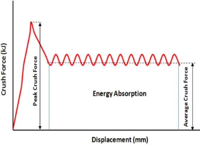
In order to evaluate the crash performance of energy-absorbing structures, it is necessary to de-fine the crashworthiness indicators. The parameters of crashes are shown in Figure 1, such as energy absorption, PFC, and SEA which can be used to evaluate the efficiency of structures. En-ergy absorption is calculated as:
0
d
s
E
F (1)Where F is the crashing force with the function of the displacement , and s is the
displace-ment before failure of the specimen. The equation for SEA indicates the absorbed energy (ET )
per unit mass (MT) of a structure is:
T T
E SEA
M
(2)
where MT is the structure’s total mass. In this case, the higher value indicates the greater energy
absorption efficiency of a material.
Figure 1: Diagram of Crush force vs. Displacement.
The average crush force (Favg) is the response parameter for the energy absorption capability:
avg T
E F
d
(3)
where total energy is absorbed (ET ) during collapse and displacement (d). The crush force
effi-ciency is defined as the ratio of the average crush force (Favg) to the peak crush force Fmax.
avg max F CFE
F
(4)
3 METHODS AND MATERIALS
3.1 Finite element models
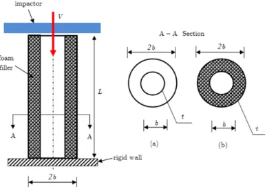
Empty and foam-filled double structures are analyzed for the numerical solution. The length (L)
of the model aluminium foam-filled double tube is 250 mm, outer and inner wall diameters are,
2b 64 mm and b 32 mm, respectively and outer and inner wall thickness are both, t0 and
i
t 1.8 mm (Figure 2).
Figure 2: Thin-walled tube under axial impact loading with dimensions and boundary loading conditions: (a) empty double tube, and (b) foam-filled double tube.
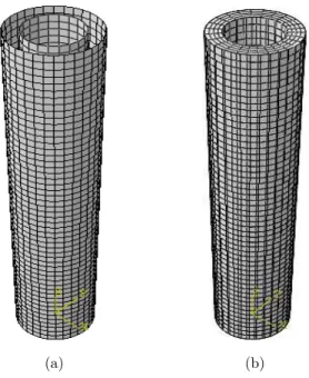
Other parameters are the yield stress of the aluminium thin-walled tubes (y) and the density of the foam filler (f ). The bottom of the thin-walled tube is boundary conditions and the top is impacted a constant velocity by a moving rigid wall. Two types of loading speeds usually faced in a passenger vehicle crash event are simulated, i.e. 1 m/s for quasi-static and 10 m/s for dynam-ic impact. The impactor (110 kg) is attached to the top free end. The circular tubes such as bumper beam can absorb the kinetic energy about 10% of the compact car’s mass (1,100 kg) ac-cording to Witteman (1999). Simulations of the crushing behaviour of the circular tubes are cre-ated by non-linear explicit finite element (FE) software code. The FE models for double empty and foam-filled tubes are described in Figure 3.
The tubular tubes wall are modelled using four node shell continuum elements with five inte-gration points along the element’s thickness direction. The eight node continuum elements are used to model foam filled tube with a reduced integration technique combined with the hourglass control. Moreover, the enhancement-based hourglass control and reduced integration are applied to avoid both artificial zero energy deformation modes and volumetric locking. The element size of 2 mm is chosen based on a mesh convergence study of shells and foam elements. To ensure a sufficient mesh density and to accurately capture the deformation process, the mesh convergence is addressed. Meanwhile, the contacts between as a finite sliding penalty based contact algorithm, with contact pairs and a hard contact, the foam and the tube walls are modelled. The friction coefficient value was set at 0.3 for all contact surfaces (Guo et al., 2011a; 2011b).
(a) (b)
Figure 3: Finite element model of double cylindrical tubes: (a) empty tube, and (b) foam-filled tube.
3.2 Material properties
The thin-walled circular tubes are fabricated using aluminium alloy A6063 T6 (Guo et al., 2011a; 2011b) with mechanical properties of young’s modulus E 59 GPa, Poisson’s ratio 0.3 and
density 2700 kg/m3. Moreover, Figure 4 showed the uniaxial tension test with different thickness (1.0, 1.6 and 2 mm).
The Von Mises’s isotropic plasticity algorithm as an elastic-plastic material model is used to assess the structures constitutive behaviour. To define plastic hardening in the material’s consti-tutive model, piecewise lines are performed. It found from the true stress and the plastic strain of experimental datas. Therefore the effect of strain rate in this model is considered, the insensitivity of strain rate of aluminium alloy material (Langseth et al., 1999).
Figure 4: The uniaxial tensile stress-strain curves of profile material (Guo et al., 2011a; 2011b).
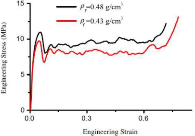
In addition, the average mechanical property values of aluminium closed-cell foam filler are ap-plied, with nominal density f 0.45 g/cm3, young’s modulus E 625 MPa. The engineering
stress-strain curve with different foam density (0.48 and 0.43 g/cm3) is shown in Figure 5.
Figure 5: The uniaxial compression stress-strain curves of aluminum foams(Guo et al., 2011a; 2011b).
Dehspande and Fleck (2000) developed the constitutive behaviour which was based on an iso-tropic uniform material of the foam model. In this work, all of model are developed by non-linear ABAQUS/Explicit software packages. In addition, to calculate the plastic behaviour of the alu-minium foam, the crushable foam and the crushable foam hardening options were used. The equation of yield criterion in this model is described as,
ˆ 0
F Y (5)
where,
2 2 2
2
1 ˆ
1 3
e m
(6)
where, e is the effective Von Mises stress and m denotes the mean stress. The yield strength (Shahbeyk, 2007) is defined as Y. In addition, is the parameter used to define the shape of the
yield surface and the plastic coefficient function p. The plastic Poisson’s ratio for aluminium foam repoted by Ahmad and Thambiratnam (2009); Reyes et al. (2003) is zero, thus the parame-ter can be calculated as follows,
2 2 1 2
9 1
p p
(7)
The strain hardening effect equation for the initial model is defined by Ahmad and Thambi-ratnam (2009) as,
2 ˆ 1 ln 1 ˆ P D D Y (8)where, p is the plateau stress, the material constants are 2, , D and , and the effective strain is defined as ˆ. The strain of densification is derived as,
0 2 2 9 ln 3 f D f
(9)
According to Hou et al. (2009); Ahmad and Thambiratnam (2009), the density of foam and the base material is defined as f and
0
f
respectively.
3.3 Metamodel technique using RBF and D-Optimal
The D-optima as design of experiment was used to reduced sample number for constructing met-amodel (Kleijnen, 2005; Song et al., 2013). In addition, Metmet-amodel technique, i.e. Radial basis functions (RBF) represent the relationship between the individual objective functions and the design variable vector. the RBF approximation of response function f
x was derived from theFE simulation as the following expression:
1
n
i i
i
f x x x
(10)where the design variable vector and response values at n arbitrary design (training) points, x is
the vector of normalised design input variables, with xi representing the normalised coordinates
of the i training point, is a radial symmetric basis function, i 1 is the unknown
interpola-tion coefficients, and
T
i i i i
r xx xx xx . The range of r is (0, 1) with 0 <c ≤ 1,
and c is problem specific to the basis function and tuning parameters.
The RBF method has a fairly good accuracy for the global approximation of highly non-linear responses and it has been successfully used in previous crashworthiness optimizations by Rais and Singh (2003); Fang et al. (2005a; 2005b); Salehghaffari (2011). The radial basis function meta-models used the equations shown in Table 1.
Thin-plate spline
r r2log
rGaussian
2, 0
r
r e
Multiquadratic
r r2c2Inverse multiquadratic
r 1 r2c2Table 1: RBF formulations used for the analysis.
3.4 Multi-objective optimization using NSGA II
The main purpose of this study is to optimise foam-filled double aluminium tubes to maximise crashworthiness performance under axial impact loading. This is referred to as a multi-objective optimization scheme. In general, the mathematic formulation of multi-objectives can be expressed as:
1 , 2 ,...,
st. and
0, 1,..., 0, 1,...,
T n
m L u
u v
F x f x f x f x
x R x x x
g x u s
h x v p
(11)
Where x is the design variable vector, n is number of the objective function, fn
x is theobjec-tive function, L
1L, 2L,..., L
nx x x x denotes the lower bound, u
1u, 2u,..., u
nx x x x denotes the upper
bound of the design variables, s and p are the number of unequal and equal constraints,
respec-tively. Franulovic et al. (2009) indicated the advantage of the genetic algorithm for instance it avoids trapping when searching for an optimum within local optima. Whereas, Deb (2001) ex-plained the benefits of the NSGA II such as more effective and efficient in ranking solutions, as-signing ranking fitness, and benchmarking number problems.
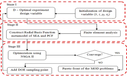
The flowchart of the optimization process for the multi-objective procedure is shown in Figure 6. It clarifies the multi-objective optimization using FE analysis, MATLAB software is used for RBF and NSGA II. However, the NSGA II based on a fast non-dominated sorting principle was performanced by Hanssen et al. (2001) to calculate the Equation 11.
Figure 6: Flowchart of crashworthiness multi-objective optimization.
4 RESULTS AND DISCUSSION
4.1 Model validation
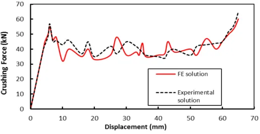
Finite element models should be compared to theoretical solutions or experimental data in litera-ture (Li et al., 2012) to ensure they are sufficiently accurate for design optimization. The
age of peak crushing force difference between the experiment test and the simulation (Figure 7) are 1.42%. The deformation patterns also between the simulation and the test shown in Figure 8 suggest the model was relatively similar (good agreement) and it could be continued for design optimization (Djamaluddin et al., 2014; 2015).
Figure 7: Crushing force versus Displacement.
(a) (b)
Figure 8: Deformation pattern of tubular tubes: (a) FE, and (b) experimental solution (Li et al., 2012).
4.2 Finite element analysis
The configuration of the two optimal deforms of empty and foam-filled double circular are shown in Figure 9. Note that the two double circular tubes designs developed some stable folding pat-terns.
(a) (b)
Figure 9: Deformation mode of double circular tubes: (a) empty, and (b) foam-filled tube.
It can be seen that the double circular foam-filled tube has greater resilience than the empty structure in the same deformation time. This proves that the foam-filled tube has more ability to absorb energy than the empty tube, because of the frictional interaction between the walls of the inner and outer tubes and the foam filling, as reported by Zhang et al. (2012).
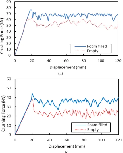
The deformation mode represented in the crushing force versus the displacement is plotted in Figure 10. The maximum crushing force on the foam-filled tube under a dynamic loading is 74.32 kN and a quasi-static loading is 43.43 kN. Similarly, for the empty structures the maximum crushing forces under dynamic and quasi-static loads are 45.54 kN and 38.46 kN, respectively.
(a)
(b)
Figure 10: Crushing force vs. Displacement of the structures for the cases of: (a) dynamic impact, and (b) quasi-static impact.
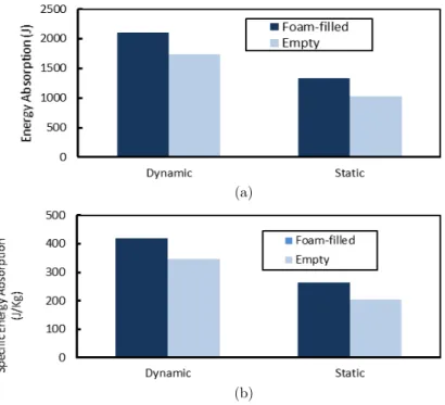
In addition, the values under quasi-static load conditions are lower than the values under dynam-ic load conditions, showing the effects of impacts differed according to the characteristdynam-ics of the structures. The energy absorption and specific energy absorption capability of both tubes showed the foam-filled double tube is more effective than the empty tube under dynamic and quasi-static load, as shown in Figure 11.
(a)
(b)
Figure 11: Structures under quasi-static and dynamic impacts: (a) energy absorption, and (b) specific energy absorption.
In addition, when the velocity is analyzed, it was found that the EA and SEA of the foam-filled double tube increases approximately 49.43% when compared to the empty tube, at a rigid wall impact speed of 10 m/s. The EA of the empty double tube increases more than 46.43% under dynamic impact when compared to the quasi-static impact.
These results describe significantly different values between the EA and SEA of foam-filled and empty tubes, due to the frictional interaction between the aluminium wall and the foam fill-ing. Moreover, the EA and SEA values also increase when the velocity is increased. To reduce the required sample number for constructing the radial basis function meta-models, in this case the crashworthiness performance is formulated using the D-optimal technique.
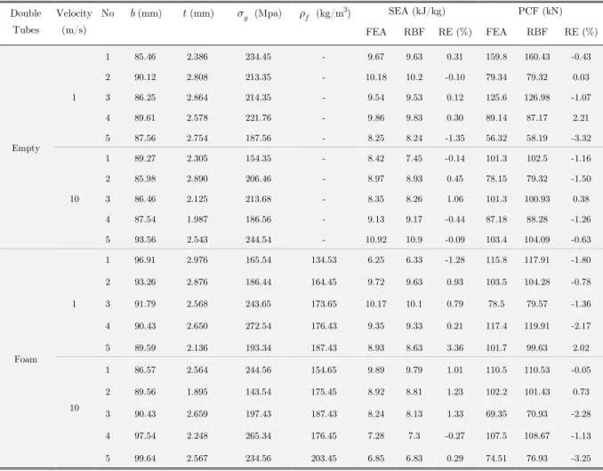
However, the constructed radial basis function meta-models must be validated, because they directly affect the optimization results. The RBF meta-model should be accurate at the sample points around in which it is constructed. To validate the models, five extra random points are generated in the design domains of the four types of tubes, which are impacted at 1 m/s and 10 m/s. Both the FE model and the RBF meta-model are used to predict the SEA and PCF re-sponses at these validation points. To measure the approximation degree of the RBF meta-model against the FE analysis, the relative error (RE) is evaluated as:
y x y x
RE
y x
(12)
where y x
is the radial basis function model and y x
is the finite element result. The modelresults for the FE and RBF of the double empty and foam-filled tubes under axial and oblique
impact angles, are obtained from the equation 12. The error between the FE analysis and the RBF model at the five random sample points are summarised in Table 2. The RBF meta-model approximation is less than 3.5%. However, in the design optimization the RBF model provided sufficient accuracy.
Double Tubes
Velocity (m/s)
No b(mm) t(mm) y (Mpa) f (kg/m3) SEA (kJ/kg) PCF (kN)
FEA RBF RE (%) FEA RBF RE (%)
Empty 1
1 85.46 2.386 234.45 - 9.67 9.63 0.31 159.8 160.43 -0.43
2 90.12 2.808 213.35 - 10.18 10.2 -0.10 79.34 79.32 0.03
3 86.25 2.864 214.35 - 9.54 9.53 0.12 125.6 126.98 -1.07
4 89.61 2.578 221.76 - 9.86 9.83 0.30 89.14 87.17 2.21
5 87.56 2.754 187.56 - 8.25 8.24 -1.35 56.32 58.19 -3.32
10
1 89.27 2.305 154.35 - 8.42 7.45 -0.14 101.3 102.5 -1.16
2 85.98 2.890 206.46 - 8.97 8.93 0.45 78.15 79.32 -1.50
3 86.46 2.125 213.68 - 8.35 8.26 1.06 101.3 100.93 0.38
4 87.54 1.987 186.56 - 9.13 9.17 -0.44 87.18 88.28 -1.26
5 93.56 2.543 244.54 - 10.92 10.9 -0.09 103.4 104.09 -0.63
Foam 1
1 96.91 2.976 165.54 134.53 6.25 6.33 -1.28 115.8 117.91 -1.80
2 93.26 2.876 186.44 164.45 9.72 9.63 0.93 103.5 104.28 -0.78
3 91.79 2.568 243.65 173.65 10.17 10.1 0.79 78.5 79.57 -1.36
4 90.43 2.650 272.54 176.43 9.35 9.33 0.21 117.4 119.91 -2.17
5 89.59 2.136 193.34 187.43 8.93 8.63 3.36 101.7 99.63 2.02
10
1 86.57 2.564 244.56 154.65 9.89 9.79 1.01 110.5 110.53 -0.05
2 89.56 1.895 143.54 175.45 8.92 8.81 1.23 102.2 101.43 0.73
3 90.43 2.659 197.43 187.43 8.24 8.13 1.33 69.35 70.93 -2.28
4 97.54 2.248 265.34 176.45 7.28 7.3 -0.27 107.5 108.67 -1.13
5 99.64 2.567 234.56 203.45 6.85 6.83 0.29 74.51 76.93 -3.25
Table 2: RBF metamodels of foam-filled tube validation under axial impact.
For multi-objective optimization, there are more than one objective and trade-offs between two or more conflicting objectives. The design variables are the level of SEA and PCF defined in Equa-tion 6, enabling a comparison to be made of the calculated crashworthiness of empty and foam-filled structures.
New objectives and constraint functions for double circular tubes with respect to design varia-bles such as b, t, y and f were constructed from Equations 12–14 and the SEA and PCF.
MOD problems can be calculated to obtain the Pareto fronts, as shown in Equations 13–14. Based on radial basis function metamodels, the NSGA-II algorithm is adopted to investigate the design space and create an initial 200 design point population for all cases of MOD. By consider-ing the convergence of optimizations iteratconsider-ing for 30 generations, the PCF versus SEA Pareto front graphs are generated using NSGA-II for the tube structures. It can be clearly seen that they
conflict with each other in all SEA and PCF design case criteria. Each of the double tubes shows an increasing SEA which leads to undesirable PCF levels, as seen in Figures 12–13.
Figure 12: Pareto fronts of SEA vs. PCF or empty and foam-filled double circular tubes under quasi-static impact loading.
Figure 13: Pareto fronts of SEA vs. PCF for empty and foam-filled double circular tubes under dynamic impact loading.
Case one: Empty double circular tube
This tube is represented by the inner diameter wall (bi), outer diameter wall (b0) which 2bi b0 b, tube wall thickness (t), and tube wall material (y). The multi-objective design
problem is shown as follows,
SEA , , , PFC , ,
st.SEA 10.92 kJ/kg 85 mm 100 mm 1.6 mm 3.2 mm 140 MPa 280 MPay y
y
b t b t
b t
(13)
Case two: Foam-filled double circular tube
The foam-filled double tube with f as the density of the foam filler is calculated using multi-objective optimization:
3 3
SEA , , , , PFC , , , st.SEA 10.92 kJ/kg
85 mm 100 mm
1.6 mm 3.2 mm
140 MPa 280 MPa
130 kg/m 270 kg/m
y f y f
y f
b t b t
b t
(14)
4.3 Comparison of empty and foam-filled double circular tubes
The multi-objective optimizations shown in Eqs. 14–15 are used to compare the crashworthiness of the structures. The foam-filled double circular tube has the same design variable dimensions and boundary and loading conditions. The comparison of deformation patterns in the different structures can be seen Figure 11. The energy absorption was plotted against the deformation length for different design concepts. In summary, the empty geometry had lower energy absorp-tion under axial loads. Based on Figs. 14–15, it is shown that the foam-filled configuraabsorp-tion has better energy absorption than the empty geometry. The combination structures have lower peak crushing force and more energy absorption capacity due to the frictional interaction between the foam-filler and the inner and outer tubes. Thus, this type of structure can improve the crashwor-thiness performance in thin-walled tubes, especially associated with vehicle design.
Figure 14: Pareto fronts of SEA vs. PCF of single and double foam-filled tubes under quasi-static impact loading.
Table 3 lists the optimal configuration of empty and foam-filled tubes (columns 4–7) and the ide-al vide-alues for two objective functions: SEA (column 8) and PCF (column 9). First, for each of the structure designs in this table, the maximum SEA at 18.54 kJ/kg is achieved when the empty tube is under axial impact. The preferable wall thickness value is 2.643 mm which the material yield stress is 200.73 MPa.
Double Tubes Velocity (m/s) Objec-tive Function
b(mm) t(mm) y (MPa) f (kg/m3) SEA (kJ/kg) PCF (kN)
Empty
1 SEA 92.97 2.451 197.54 - 16.46 134.45
PCF 96.43 2.345 210.63 - 4.87 53.91
10 SEA 93.64 2.643 200.73 - 18.54 146.92
PCF 97.19 2.943 199.32 - 6.87 60.34
Foam
1 SEA 93.25 2.102 203.76 210.65 7.86 46.54
PCF 98.43 2.451 208.81 149.87 1.56 39.54
10 SEA 96.43 2.991 208.34 205.38 9.95 59.54
PCF 99.74 2.459 205.62 169.21 2.56 46.54
Table 3: Optimal designs of double circular structures under quasi-static and dynamic impact.
This shows a contradiction between the two objective crashworthiness functions, and the MOD is applied in such situations. Second, the optimal diameter of each double circular tube for maxi-mum SEA generally varies under each type of impact condition. For example, the optimal sec-tional diameter of the foam-filled tube under axial impact to achieve maximum SEA is 85.61 mm. Third, the minimum PCF is close to 146.32 kg/m3 for both impact angles in the foam-filled tubes. The optimal SEA value on impact of the double tube, was found at the highest foam density of 219.65 kg/m3. However, the optimal foam density for SEA maximisation is lower under pure qua-si-static impact than dynamic impact (Hou et al., 2009).
The multi-objective optimization was explored with respect to the design variables of wall di-ameter (b); outer thickness of wall (t0); inner thickness of wall (ti); yield stress of the tubes
(y), and density of the foam filler (f).
4.4 Comparison of single and double foam-filled circular tubes
The traditional foam-filled single tube was chosen and compare to the double cylindrical tube, where Eq. 15 defines the multi-objective optimization.
Case three: Foam-filled double circular tube
3 3
SEA , , , , PFC , , , st.SEA 10.92 kJ/kg
85 mm 100 mm
1.6 mm 3.2 mm
140 MPa 280 MPa
130 kg/m 270 kg/m
y f y f
y f
b t b t
b t (15)
The single circular tube had a diameter of 64 mm, was 250 mm in length, and had the same de-sign variables, boundary, and loading conditions described in Figure 2. New objective and con-straint functions were constructed by the RBF, with respect to design variables b, t, f , y for
the foam-filled single circular tube.
The Pareto fronts for quasi-static and dynamic impact loads on foam-filled single and double circular tubes, using RBF meta-models and NSGA II optimization, are plotted in Figs. 14–15. Again, it can be seen that the Pareto front of the single tubular structure is worse than the dou-ble circular tube. This means from a safety view point the doudou-ble tube absorbs more energy un-der the same level of peak impact force. In these conditions the double structure appears to be a potentially better crashworthiness structure.
5 CONCLUSIONS
The crashworthiness design for thin-walled aluminium foam-filled circular tubes was explored in this paper. Criteria such as the specific energy absorption and peak crushing force were calculated under axial impact loadings at different impact velocities. The multi-objective problems based on the radial basis function were constructed using finite element analysis for the design variables. The maximum SEA and minimum PCF under quasi-static loading is 16.46 kJ/kg and 53.91 kN, respectively. However, under dynamic impact loading, the maximum SEA is 19.54 kJ/kg and the minimum PCF is 46.54 kN. It was also found that an increase in the impact speed on the tube led to an increase in the specific energy absorption and peak crushing force.
NSGA-II was used in the multi-objective optimization of the SEA and PCF values in circular double structures. The optimization process examined both empty and foam-filled double and single tubes. Under pure axial impact, the results showed that the crashworthiness performance of the foam-filled tube improved compared to the empty tube, and the performance of the double structure improved compared to the single tube. This demonstrates that double cylindrical tubes have good potential energy absorbing attributes in crashworthiness structure applications, which can protect vehicle occupants involved in accidents or collisions.
References
Acar, E., Guler, M.A., Gerçeker, B., Cerit, M.E., Bayram, B., (2011). Multi-objective crashworthiness optimiza-tion of tapered thin-walled tubes with axisymmetric indentaoptimiza-tions. Thin-wall Struct 49: 94-105.
Ahmad, Z., Thambiratnam, D.P., (2009). Dynamic computer simulation and energy absorption of foam-filled conical tubes under axial impact loading. Computers and Structures 87(3-4): 186–197.
Alexander, J.M., (1960). An approximate analysis of the collapse of thin cylindrical shells under axial loading. Q J Mech Appl Math 13: 10–15.
Alghamdi, A.A.A., (2001). Collapsible impact energy absorbers: an overview. Thin-Walled Struct 39(2): 189–213. Deb, K., (2001). Multiobjective optimization using evolutionary algorithms. John Wiley & Sons.
Deshpande, V.S., Fleck, N.A., (2000). Isotropic constitutive models for metallic foams. Journal of the Mechanics and Physics of Solids 48: 1253–1283.
Djamaluddin, F., Abdullah, S., Ariffin, A.K., Nopiah, Z.M., (2014) Multi-Objective Optimization of Aluminum Foam Filled Double Tubes Subjected to Oblique Impact Loading for Automobile Bumper Beam. Applied Mechan-ics and Materials 663: 93-97
Djamaluddin, F., Abdullah, S., Ariffin, A.K., Nopiah, Z.M., (2015). Optimization of foam-filled double circular tubes under axial and oblique impact loading conditions. Thin-walled structures 87: 1-11.
Fang, H., Rais-Rohani, M., Liu, Z., Horstemeyer, M.F., (2005). A comparative study of metamodeling methods for multiobjective crashworthiness optimization. Computers and Structures 85: 2121–2136.
Fang, H., Wang, Q., (2008). On the effectiveness of assessing model accuracy at design points for radial basis functions. Commun Numer Methods Eng 24: 219–235.
Franulovic, M., Basan, R., Prebil, I., (2009). Genetic algorithm in material model parameters identification for low-cycle fatique. Compt mater Sci 75: 505-510.
Guo, L.W., Yu, J.L., (2010a). Bending response of sandwiched double tube structures with aluminum foam core. In: Lu, J.W.Z., Leung, A.Y.T., Iu, V,P., Mok, K.M., editors. Proceedings of the ISCM II & EPMESC XII, Hong Kong-Macau, 2009. AIP CP1233, Part One. Melville, New York: American Institute of Physics. p. 602–607. Guo, L.W., Yu, J.L., (2011a). Bending behavior of aluminum foam-filled double cylindrical tubes. Acta Mech 222: 233–244.
Guo, L.W., Yu, J.L., (2011b). Dynamic bending response of double cylindrical tubes filled with aluminum foam. Int J Impact Eng 38(2–3): 85–94.
Guo, L.W., Yu, J.L., Li, Z.B., (2010b). Experimental studies on the quasi-static bending behavior of double square columns filled with aluminum foams. Acta Mech 213: 349–358.
Han, D.C., Park, S.H., (1999). Collapse behavior of square thin-walled columns subjected to oblique loads. Thin-walled Struct 35: 167–184.
Hanssen, A.G., Langseth, M., Hopperstad, O.S., (1999). Static crushing of square alumi- nium extrusions with aluminium foam filler. Int J Mech Sci 41(8): 967–993.
Hanssen, A.G., Langseth, M., Hopperstad, O.S., (2000). Axial crushing of aluminium columns with aluminium foam filler. In: Proceedings of the seventh international symposium on structural failure and plasticity (IM-PLAST2000): 401–407.
Hanssen, A.G., Langseth, M., Hopperstad, O.S., (2001). Optimum design for energy absorption of square alumi-num columns with alumialumi-num foam filler. Int J Mech Sci 43: 153-176.
Hopperstad, O.S., Langseth, M., Hanssen, A.G., (2000). Static and dynamic crushing of circular aluminium extru-sions with aluminium foam filler. Int J Impact Eng 24(5):.475–507.
Hopperstad, O.S., Langseth, M., Hanssen, A.G., (2001). Optimum design for energy absorption of square alumini-um colalumini-umns with alalumini-uminialumini-um foam filler. Int J Mech Sci 43(1): 153–176.
Hou, S., Li, Q., Long, S., Yang, X., Li, W., (2009). Crashworthiness design for foam filled thin-wall structures. Mater Des 30: 2024-2032.
Jones, N., (1989). Structural impact. Cambridge University Press.
Langseth, M., Hopperstad, O.S., (1996). Static and dynamic axial crushing of square thin-walled aluminium ex-trusions. Int J Impact Eng 18: 949-968.
Li, Z.B., Yu, J.L., Guo, L.W., (2012). Deformation and energy absorption of aluminum foam-filled tubes subjected to oblique loading. Int J of Mechanical Sciences 54: 48–56.
Liao, X.T., Li, Q., Yang, X.J., Li, W., Zhang, W.G., (2008a). A two-stage multiobjective optimization of vehicle crashworthiness under frontal impact. Int J Crashworthiness 13: 279-288.
Liao X.T., Li, Q., Zhang, W.G., Yang, X.J., (2008b). Multiobjective optimization for crash safety design of vehicle using stepwise regression model. Struct Multdiscipl optim 35: 561-569.
Lu, G., Yu, T., (2003). Energy absorption of structures and materials. Woodhead Publishing Limited.
Murugan, P., Kannan, S., Baskar, S., (2009). NGSA-II algorithm in for multiobjectivevgeneration expansion plan-ning problem. Eletric Power Syst Res 79: 622-628.
Nariman-Zadeh, N., Darvizeh, A., Jamali, A., (2006). Pareto optimization of energy absorption of square alumini-um colalumini-umns using multi-objective genetic algorithms. Proc Inst Mech Eng Part B – J Eng Manuf 220: 213-224. Rais-Rohani, M., Singh, M.N., (2003). Comparison of global and local response surface techniques in reliability-based optimization of composite structures. Struct Multidisciplinary Optim 26: 333-345.
Reid, S.R., (1993). Plastic deformation mechanisms in axial compressed metal tubes used as impact energy ab-sorbers. Int J Mech Sci 35(12): 1035-1052.
Reyes, A., Hopperstad, O.S., Berstad, T., Hanssen, A.G., Langseth, M., (2003). Constitutive modeling of alumi-num foam including fracture and statistical variation of density. European Journal of Mechanics A: Solids 22(6): 815-835.
Salehghaffari, S., Rais-Rohani, M., Najafi, A., (2011). Analysis and optimization of externally stiffened crush tubes. Thin-Walled Structures 49: 397–408.
Santosa, S.P., Wierzbicki, T., Hanssen, A.G., Langseth, M., (2000). Experimental and numerical studies of foam-filled sections. Int J Impact Eng 24(5): 509-534.
Seitzberger, M., Rammerstorfer, R.F., Degischer, H.P., Gradinger, R., (1997). Crushing of axially compressed steel tubes filled with aluminium foam. Acta Mech 125: 93-105.
Seitzberger, M., Rammerstorfer, F.G., Gradinger, R., Degischer, H.P., Blaimschein, M., Walch, C., (2000). Exper-imental studies on the quasi-static axial crushing of steel columns filled with aluminium foam. Int. J. Solids Struct. 37(30): 4125-4147.
Shahbeyk, S., Spetrinic, N., Vafai, A., (2007). Numerical modelling of dynamically loaded metal foam-filled square columns. International Journal of Impact Engineering 34: 573–586.
Sun, G.Y., Li, G.Y., Stone, M., Li, Q., (2010a). Application two-stage multi-fidelity optimization procedure for honeycomb-type. Comput Mater Sci 49: 500–511.
Sun, G.Y., Li, G.Y., Hou, S.J., Zhou, S.W., Li, W., Li, Q., (2010b). Crashworthiness design for functionally grad-ed foam fillgrad-ed thin-wallgrad-ed structures. Mater Sci Eng A 527: 1911–1919.
Thornton, P.H., (2005). Energy absorption by foam filled structures.SAE paper 800081.
Witteman, W.J., (1999). Improved vehicle crashworthiness design by control of the energy absorption for different collisions situation. Netherlands: Eindhoven University of Technology; PhD thesis.
Yin, H., Wen, G., Hou, S., Chen, K., (2011). Crushing analysis and multiobjective crashworthiness optimization of honeycomb-filled single and bitubular polygonal tubes. Mater Des 32: 4449-4460.
Yuen, S.C.K., Nurick, G.N., Starke, R.A., (2008). The energy absorption characteristics of double-cell tubular profiles. Lat Am J Solids Struct 5(4): 289–317.
Zarei, H.R., Kröger, M., (2008a). Bending behavior of empty and foam-filled beams: Structural optimization. Int J Impact Eng 35: 521-529.
Zarei, H.R., Kröger, M., (2008b). Optimization of the foam-filled aluminum tubes for crush box application. Thinwall Struct 46: 214-221.
Zarei, H.R., Kröger, M., (2008c). Optimum honeycomb filled crash absorber design. Mater Des 29: 193-204. Zhang, Y., Sun, G., Li, G., Luo, Z., Li, Q., (2012). Optimization of foam-filled bitubal structures for crashworthi-ness criteria. Mater Des 38: 99-109.