Abs tract
Light and medium protection for small naval vessels guarantees their high performance and safety during the guard duties. In this study, a protective shield fabricated from Dyneema HB25 fibers has been utilized as an add-on layer on the coast guard boat hull. Finite element analyses have been conducted using Chocron’s model. Two standards of gun-fire were employed and various thicknesses of the composite layers were examined by ballistic impacts. Afterward, numerical simulations results compared with experiments and revealed a good consistency. Finally, some graphs have been presented to help designers for choosing more conven-ient shield based on protection and weight characteristics after judgment of vessel requirements.
Key words
coast guard boat, ballistic impact, Dyneema, polymer composite, numerical simulation, FEM
weight ship against ballistic impacts: Analytical and
Experimental
1 INTRODUCTION
From the early 20th century, armor materials have been developed generally of high hardness steel. However, in the last few decades the importance of lightweight protection has led to invention of alternative materials [1]. Due to their high strength, low density, extreme toughness and their out-standing performance against small and medium caliber projectiles, polymers have become widely used in armors and the subject of many researches. In particular, when the weight is a design con-cept, protection or body armor for light weight vehicles, specially naval vessel becomes critical [2].
The prominence of manufacturing coast guard boat hull with Dyneema composite is the feasibil-ity of shaping in regards to other materials such as ceramic composites. The other factor that has to be considered in building hull is its areal weight. Dyneema composite are lighter than common high strength fabric such as Kevlar and far less than ceramics.
Weight reduction for current and future military systems is crucial in fast deployment of marine circumstances. In the near future, ultra-light weapon platforms will be promising for conquering the
I. J ali l i, Z . H . No uri *, A . Z . A ab ad y, K. A k bari V .
Mechanical Group, Marine Science Noshahr University, Noshahr, Iran
Received 26 Sep 2012 In revised form 01 Mar 2013
Latin American Journal of Solids and Structures 10(2013) 1211 – 1223
battlefields. Some military strategies set the trend for extensive weight reduction in future Army platforms that require novel technology. Therefore, New materials and design concepts are required to meet these challenges [3]. In this regard, various experimental and theoretical investigations have been carried out on the ballistic impact of composite protections, so far [4-11].
The object of the present study is to simulate ballistic impact and improving the strength of the coast guard boat hull while reducing its total weight, by employing shaped Dyneema composite layout as an outer hull layer. In order to assess the performance of this protective shield against ballistic threats, finite element method (FEM) and empirical investigation have been employed. FEM analysis has been carried out by ABAQUS/Explicit one of robust finite element analysis soft-ware. To obtain realistic results from this analysis, the mechanical and physical properties of Dyneema fibers in high strain rates fed into the software as initial data.
Furthermore, experimental investigations were also carried out on prepared sample of Dyneema composite of various thickness with different projectiles. Next, the experimental results were analo-gized with simulation predictions. Finally, some thickness selection assistant curves for building coast guard boat shield resistant to projectiles have been presented to facilitate designing based on vessel functionality and risk assessment.
2 ANALYTICAL METHOD
The highly complicated problems of a projectile impacting polymer/composite layers has already been studied thoroughly by different researchers such as; Duan [12], Karahan [13], Chocron [14] and Bürger [15]. It is not the objective of this paper to improve their impact models but simply to use them, and to build a composite one. In the following the reader can find the most important results obtained by the authors and how they have been applied to this problem.
A simple analytical model of impact onto a fabric has already been published by Chocron et. al [16] including the basis of the model. The model has been checked and a good agreement was ob-tained compared with analytical and numerical ones [17]. According to this model, the kinetic ener-gy of the projectile is transferred to the plate through two mechanisms: straining and breaking of the yarns, and delamination.
In order to analyze the first mechanism, the equation of motion of the projectile is driven:
M
pdV
dt
=
2
F
(1)In which,
M
p is the projectile mass,V
is its velocity andF
is the force being exerted from theLatin American Journal of Solids and Structures 10(2013) 1211 – 1223
Figure 1 Configuration of impact forces on the composite layers.
The force that yarns exert on the projectile estimated earlier by Chocron [17]:
F
=
E
ε
Sn
1
n
y (2)Where
F
is the component of the force in the direction of motion,E
the Young modulus of the yarns,ε
the strain of the fabric under the projectile,ny
the number of yarns in direct contact with the projectile,S
the section of the yarn andn
1 is the number of layers of the fabric.
Moreover, the analytical solution for constant velocity impact derived by Smith [18]. When a point projectile impacts a linear elastic yarn, the velocity of the projectile (
u
0) and the strain (
ε
) are related by Eq. 1:
u
0=
c
y2ε
ε
(
1
+
ε
)
−
ε
2(3)
This equation also validated for non-constant velocity impact [16]. In Eq. 3,
c
y is the longitudi-nal speed of sound in the yarn. Smith also calculated the angle between the line of impact and the yarn (Fig. 1):sin
�
=
2
�
�
(
1
+
�
)
−
�
!�
(
1
+
�
)
(4)
Smith’s model gives the strain and the angle
�
. All the yarns are assumed to have the same strain through the textile thickness to keep the analytical model simple enough; weave and crimp are not considered.Latin American Journal of Solids and Structures 10(2013) 1211 – 1223
1
2
�!
�
!!
−
�
!!
=
1
2
�
!�
!��
�
!�
!
��
!
!
(5)
Another way to write Eq. 5 is:
�
!�
!"!�
!�
!���
!=
�
!��
! ! !≡
�
(6)Where �
! is the time of failure, R is called failure constant and it is only dependent on the
con-figuration, but not on the impact velocity. Finally, �!" is the ballistic limit. With one single test
the designer can calculate R, by forcing the analytical and experimental residual velocity to be equal, and then use it to analyze all impact velocities. A more general failure model is easily de-rived: as R depends on the configuration, let Ri be the failure constant for the target
configura-tion i and R0 be the one for a reference target configuration, from Eq. 6 it follows:
�
! !�
!"�
! !�
!"! !�!
!�
!"�
! !
�
!"! !�
!=
�
! (7)This formula can be very useful if some empirical value for V50 is assumed or found
experimental-ly. For instance, Van Gorp [20] found that Dyneema (or Spectra) armors verify for fragment sim-ulating projectiles. The ballistic limit of Dyneema armors can be explicitly written with a very simple expression:
�
!"=
232
�
!.!�
!!! (8)Where
δ
is the areal density of the armour in kg/m2 and W is the mass in grams of the projectile. This equation allows the calculation of the failure constant for each configuration with the Eq. 7 and then the problem of the impact can be fully solved.It is assumed that the failure happens just under the maximum strain or strength criteria. Accord-ing to Eq. 3, higher values of impact velocity coincide with the greater magnitudes of the strain which is occurred at the beginning of the impact process (i.e. when the velocity of projectile is the maximum).
3 FINITE ELEMENT ANALYSIS
Latin American Journal of Solids and Structures 10(2013) 1211 – 1223
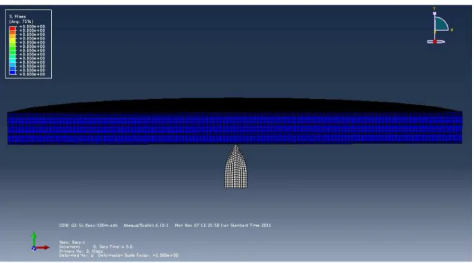
Figure 2 Boundary and initial conditions of FE model: Initial velocity (left), UX=UY=0 (Right)
The material properties of the Dyneema yarn have been given in the Table 1. Each Dyneema layer has stacked with 90 degree rotation in respect to the epoxy layer. Fig. 3 shows composite layers configuration after mesh sensitivity analysis (thinner layer is Dyneema and thicker one is epoxy).
Table 1
Mechanical properties of a single composite ply (Dyneema® HB25) [15].
ρ 970 kg/m3
E1 (in-plane) 297 GPa
E2 (out-of plane) 10.8 GPa
G12 5.0 GPa
Latin American Journal of Solids and Structures 10(2013) 1211 – 1223
Figure 3 Configuration of layers (thinner layer is Dyneema and thicker one is epoxy).
To explore the effect of impact velocity on the fabric ballistic performance, two cases are modeled by two projectiles of 7.62×51 mm NATO AP and 7.62×39 mm where the impact velocity is 780 m/s and 690 m/s, respectively and four different types of fabric, composed of various numbers of Dyneema layers; i.e. 15, 21, 27, 30 (layers), respectively.
4 EXPERIMENTAL PROCEDURE
Experiments were carried out in this work according to Table 2 condition and Fig. 4 arrangement. The composite panels were fabricated by stacking Dyneema layers with 250 MPa pressure in tem-perature of 125˚C degree for 15 min using epoxy layers. Eight shooting tests were carried out ac-cording to NIJ 0101.03 standard. Two types of projectiles used in these tests are 7.62×51 mm NATO AP and 7.62×39 mm. The shooting results are presented as complete penetration (CP), partial penetration (PP) or no penetration (NP). After shootings, the depth and diameter of trauma formed on the backing material were measured (table 4).
Table 2
Test Condition According to NIJ 0101.06
21°C ± 2.9°C
Test Temperature
50% ± 20%
Humidity
50 deg
Angle of Bullet Encounter
10 Days
Test Endurance
140 X 610 X 610 mm3
Latin American Journal of Solids and Structures 10(2013) 1211 – 1223
Figure 4 Test arrangement
5 RESULTS AND DISCUSSION
The finite element model of the projectile and armor was shown in Fig. 3. Due to the axi-symmetric nature of the problem, only half of the projectile-armor system is modeled. Eight different experi-ments, with two types of projectile and four different thicknesses, were analyzed by FEM simulation and analytical model using the proposed models. The residual velocities of projectiles after impact on composite plates are presented in Table 3.
Table 3
Ballistic results of Dyneema layout from simulation and analytical model
Type of projectile
Test No.
No. of Layers
Impact Velocity
[m/s]
Residual Veloci-ty [m/s]
(Simula-tion)
Residual Velocity
[m/s] (Analytical)
7.62×39 mm (AK-47)
1 15 690 493 415
2 21 690 345 278
3 27 690 115 93
4 30 690 0 (PP) 0 (NP)
7.62×51 mm (G-3)
5 15 780 586 518
6 21 780 442 385
7 27 780 224 145
Latin American Journal of Solids and Structures 10(2013) 1211 – 1223
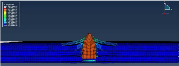
As it seen in Table 3, there is a difference between the results of residual velocity of projectile in simulation and analytical model. The simulation method is more close to experimental results (Ta-ble 4). This divergence arises from completely different approaches for calculating projectile residual velocity. Fig. 5 demonstrates the penetration of 27 layered Dyneema plate by a 7.62×39 mm projec-tile with the initial velocity of 690 m/s.
Figure 5 Complete penetration of 27 layered Dyneema plate by a 7.62×39 mm projectile (the colors demonstrate the velocity).
Verification of simulation and analytical results by experimental tests is carried out by real ballistic test. As mentioned before, shooting tests are done according to NIJ 0101.03 standard. For each eight case, three shootings executed on the fabricated Dyneema plates. The penetration results of practical shooting tests are presented in Table 4. AK-47 and G-3 bullet penetration in 25 layers specimen can be observed in Fig. 6.
Latin American Journal of Solids and Structures 10(2013) 1211 – 1223
(AK-47) 3 28 0.5 PP
4 30 0.2 PP
7.62×51 mm (G-3)
5 20 1.5 CP
6 25 1.1 CP
7 28 0.9 CP
8 30 0.4 PP
Latin American Journal of Solids and Structures 10(2013) 1211 – 1223
Figure 7 Protected areas which are fabricated with Dyneema composite
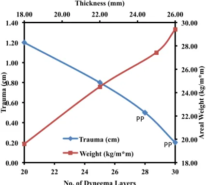
However, by increasing hull thickness the protection increases along with its areal weight. If length of trauma is considered as symbol of less protection; Fig. 8 shows the required thickness for having both protection and less weight of the hull fabricated from Dyneema fibers against 7.62×39 mm projectile. The defined element which is related to the degree of fabric protection is the value of trauma (the raised part on composite’s back that is caused by a bullet). The two completely pene-trated (CP) points in Fig. 8 indicate unsafe thicknesses for the hull.
Figure 8 Thickness selection assistant curve for building coast guard boat shield resistant to 7.62×39 mm projectile
18.00 20.00 22.00 24.00 26.00
18.00 20.00 22.00 24.00 26.00 28.00 30.00 0.00 0.20 0.40 0.60 0.80 1.00 1.20 1.40
20 22 24 26 28 30
Thickness (mm) A re al W ei gh t (k g/ m*m) T rau ma (c m)
No. of Dyneema Layers Trauma (cm)
Weight (kg/m*m)
PP
Latin American Journal of Solids and Structures 10(2013) 1211 – 1223
Figure 9 Thickness selection assistant curve for building coast guard boat shield resistant to 7.62×51 mm projectile
According to Fig. 9 by increasing the projectile caliber, the protection decreases. In this condition more Dyneema layers are required to fully stop the projectile (PP). As could be observed in Fig. 8 and Fig. 9, 27 and 30 Dyneema layers are the minimum required layer to fully stop the 7.62×39 mm and 7.62×51 mm projectiles respectively as stated by experiment. However, utilizing more layer costs extra weight which has an adverse effect on ship performance the designers should select the best configuration based on vessel functionality and assessment of projectile caliber, distance and risk.
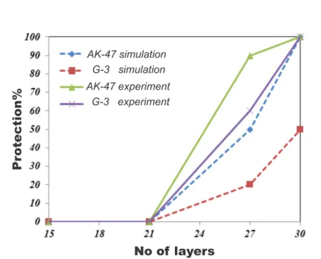
In order to compare simulation and experimental results, Fig. 10 presents percent of protection relative to number of layers for AK-47 and G-3 bullets. The percentage of protection is defined as the ratio of remaining (un-penetrated) thickness to the initial (before penetration) thickness.
����������%
=
�
_
���������
�
_�����
×
100
(9)As can be observed, simulation and experimental results have good correlation but simulation re-sults underestimate the protection level. It could be demonstrated because of idealistic model of composite layers, properties and bullet velocity.
18.00 20.00 22.00 24.00 26.00 0.00 0.20 0.40 0.60 0.80 1.00
20 22 24 26 28 30
A re al W ei gh t (k g/ m*m) T rau ma (c m)
No. of Dyneema Layers trauma (cm)
CP
Latin American Journal of Solids and Structures 10(2013) 1211 – 1223
Figure 10 Percent of protection vs. number of layers for AK-47 and G-3 (simulation and experimental)
5 RESULTS AND DISCUSSION
The results can be summarized into the following:
1 - The analytical model developed by Chocron has been employed in order to predict the motion and projectile velocity after impact.
2 - Finite element method is utilized by ABAQUS/Explicit program. The simulation results have analogized by analytical model which revealed some discrepancies between those results.
3 - Experimental results show that at least 27 Dyneema layers are required to fully stop the 7.62×39 mm projectile and at least 30 layers for 7.62×51 mm projectile, however simulation results predicts 30 Dyneema layers for both projectiles and analytical results predicts 30 Dyneema layers for both projectiles.
4 - Both analytical and simulation methods (especially analytical) slightly underestimate the protec-tion level of Dyneema fabric relative to experimental results, however, they are very useful in exam-ining other conditions which are costly or nor practical and prediction of protection level.
5 - Dyneema fabric is a suitable choice for building coast guard boat hull, because of its easy mold-ing and shapmold-ing, high strength and lightness.
6 - Trauma length and aerial weight for both projectiles versus number of Dyneema layers have been shown to assist designers for selection of more convenient protection shield regarding to vessel functionality and existent threats considering extra cost and ship performance.
Latin American Journal of Solids and Structures 10(2013) 1211 – 1223 and Engineering 259(2): 155-161.
[4] Anderson J., C.E. and Bodner, S.R. (1988). Ballistic impact: The status of analytical and numerical modeling,
International Journal of Impact Engineering 7(1): 9-35.
[5] Guoqi, Z., Goldsmith, W. and Dharan, C.K.H. (1992). Penetration of laminated Kevlar by projectiles—I: Ex-perimental investigation, International Journal of Solids and Structures 29(4): 399-420.
[6] Jenq, S.T., Jing, H.S. and Chung, C. (1994). Predicting the ballistic limit for plain woven glass/epoxy composite laminate, International Journal of Impact Engineering 15(4): 451-464.
[7] Goldsmith, W., Dharan , C.K.H. and Chang H. (1995). Quasi-static and ballistic perforation of carbon fiber laminates, International Journal of Solids and Structures 32(1): 89-103.
[8] Potti, S.V. and Sun, C.T. (1997). Prediction of impact induced penetration and delamination in thick compo-site laminates, International Journal of Impact Engineering 19(1): 31-48.
[9] Morye, S.S., et al. (2000). Modelling of the energy absorption by polymer composites upon ballistic impact,
Composites Science and Technology 60(14): 2631-2642.
[10] Billon, H.H. and Robinson, D. J. (2001). Models for the ballistic impact of fabric armour. International Journal of Impact Engineering 25(4): 411-422.
[11] Cheeseman, B.A. and Bogetti, T.A. (2003). Ballistic impact into fabric and compliant composite laminates,
Composite Structures 61(1–2): 161-173.
[12] Duan, Y., et al. (2006). Finite element modeling of transverse impact on a ballistic fabric, International Journal of Mechanical Sciences 48(1): 33-43.
[13] Karahan, M., Kuş, A. and Eren, R. (2008). An investigation into ballistic performance and energy absorption capabilities of woven aramid fabrics, International Journal of Impact Engineering 35(6): 499-510.
[14] Chocron, S., et al. (2008). Lightweight polyethylene non-woven felts for ballistic impact applications: Material characterization, Composites Part B: Engineering 39(7-8): 1240-1246.
[15] Bürger, D., et al. (2012). Ballistic impact simulation of an armour-piercing projectile on hybrid ceramic/fiber reinforced composite armours, International Journal of Impact Engineering 43: 63-77.
[16] Chocron , S., Rodriguez, J. and Sánchez Gálvez, V. (1997). A Simple Analytical Model for Ballistic Impact in Composites, HAL - CCSD.
[17] Chocron Benloulo, I.S. and Sánchez-Gálvez, V. (1998). A new analytical model to simulate impact onto ceram-ic/composite armors, International Journal of Impact Engineering 21(6): 461-471.
[18] Smith, J.C., McCrackin, F.L. and Schiefer, H.F. (1958). Stress-Strain Relationships in Yarns Subjected to Rapid Impact Loading, Textile Research Journal 28(4): 288-302.
[19] Prosser, R.A. (1980). The Penetration of Nylon Ballistic Panels by Fragment Simulating Projectiles.