Abs tract
The paper is devoted to develop a new scheme to calculate imped-ance matrices for axial-symmetric foundations embedded in half-space medium. The half-half-space medium can be approximated by increasing thickness of one layer stratum on rigid bedrock due to the effect of material damping. However, as thickness increases, the numerical problem will arise. This problem is caused by the numerical contamination by some negligible reflection waves from rigid bedrock. In reality, the effect of these reflection waves on impedance is getting small as the thickness of the one layer stra-tum increases. Therefore, the scheme will employ the solutions for one layer stratum with suppressing these reflection waves to gen-erate the impedance for the case of half-space. The numerical results by the presented scheme are compared with the results by other scheme in order to show that the new numerical scheme is effective and the solutions in layered medium can be extended to obtain the results for the cases of layered half-space medium. Some numerical results of torsional, vertical, horizontal, coupling and rocking impedances with different embedded depths will be presented and comments on the numerical scheme will be given.
Key words
Wave propagation, Impedance matrix, Dynamic stiffness and Soil-structure Interaction.
Calculation
of
impedances
for
axial
symmetric
foundation embedded in half-space medium using
solutions for one layer stratum
1 INTRODUCTION
For many decades, the vibration of foundation embedded in half-space or layered media has at-tracted some attentions. Therefore, there are many approaches to deal with this problem. In the early time, the finite element method has been popular to determine the impedance functions for foundation embedded in an elastic stratum. In the model, the soil medium can be divided into near-field and far-near-field. For the near-near-field, regular meshing of finite element method is employed. For the far-field, infinite element is used to model the semi-infinite domain [1,2]. In order to improve the
Ie - L un g C h un ga, G in - Sh ow L io u*, b
a
Institute of Applied Mechanics, National Taiwan University, Taipei, Taiwan
bDepartment of civil Engineering, National
Chiao-Tung University, Hsin-Chu, Taiwan 30049
Received 29 Oct 2012 In revised form 01 Mar 2013
Latin American Journal of Solids and Structures 10(2013) 1225 – 1241
deficiency of infinite element model, Gupta et al [3] and Tzong and Penzien [4] employed analytical approach to simulate the outgoing waves in the far-fields of half-space and layered media respective-ly.
Regarding boundary element method (BEM), Green’s function in frequency domain for layered half-space medium developed by Luco and Apsel [5] is employed. The impedance functions for foundation embedded in layered half-space using the Green’s function was generated [6,7]. However, using boundary element method to compute impedance functions, one has to deal with singularity problem by avoiding coincidence between source and observation points. Also, cone model was de-veloped to calculate the dynamic response of a disk on surface of a soil layer resting on flexible rock subjected to harmonic excitations [8]. Furthermore, the concept of cone model was extended to cal-culate the dynamic stiffness for foundation embedded in a multiple-layered half-space [9].
Regarding the method using analytical solution, Liou has developed a technique to decompose boundary conditions in the way to match the boundary values of general solution of wave equations in cylindrical coordinates for the cases of layered media [10]. The technique has been successfully applied to find the impedance functions for foundations on layered half-space medium [11,12] and axial symmetric foundation embedded in layered medium [13]. For the cases of foundation embed-ded in half-space medium, one can approximate the cases by increasing the thickness of a layered medium, if material damping exists in the half-space medium.
However, some numerical problems arise in the process of using the analytical solution technique as the thickness of layer increases. This is due to magnitude difference in z-direction between the exponential terms representing variation of upward reflecting waves and the exponential terms rep-resenting the variation of downward waves. The magnitude difference between upward reflecting waves and downward waves becomes enormously huge for the modes with large real parts of wave numbers in z-direction. This will make the numerical results unstable in calculation process. In the real situation, the contribution to vibrations near the embedded foundation from downward propa-gating wave should be much more important than that from upward reflecting wave, since the ma-terial damping will cause the reflecting waves decay a lot as they reach the foundation.
To remedy the numerical problem stated above, the upward propagating wave for the modes with very large real parts of wave numbers in z-direction should be suppressed or neglected. The paper is devoted to deal with this problem. The procedure developed by Liou and Chung [13] for layered medium will be modified to simulate the case of layered half-space medium.
Latin American Journal of Solids and Structures 10(2013) 1225 – 1241 2 DERIVATIONS OF MODAL SHAPES FUNCTIONS FOR CONSIDERING DOW
N-WARD WAVES ONLY
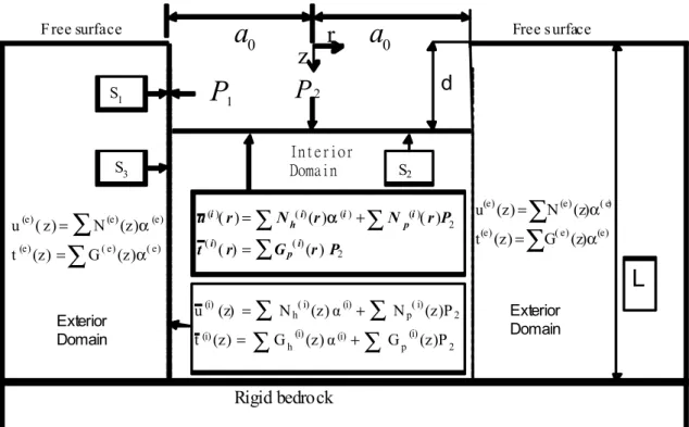
Impedance matrices for circular foundation embedded in layered medium was formulated by Liou and Chung [13]. In formulating impedances, all the solutions (modal shapes) used at the boundaries of interior domain and exterior domain are summarized in Fig. 1. In the figure, vector
P
2 (which is also defined in Fig. 2 of Reference 13) represents the nodal intensities of piecewise linear model for interaction tractions at surfaceS
2, matrices
N
andG
represent all modal shapes of displacementsand tractions respectively at interfaces
S
2,
S
3 andS
2 for interior or exterior domains, superscripts (i) and (e) ofN
andG
indicate the functions defined in interior and exterior domains respective-ly, subscript h ofN
andG
indicates homogeneous solution which satisfies the boundarycondi-tions of free surface and rigid bedrock, subscript p indicates particular solucondi-tions which satisfies properly decomposed interactions tractions of
P
2 on surfaceS
2 and rigid bedrock, vector
α
(i) and
α
(e) represent the unknown participation factors of all the modes for interior and exterior domains respectively,a
0 is radius of cylindrical cavity, d is depth of cavity, and L is thickness of layer.Figure 1 Solutions at interfaces for layered medium with cylindrical cavity.
Rigid bedrock
L
∑
∑
α = α = ) e ( ) e ( ) e ( ) e ( ) e ( ) e ( ) z ( G ) z ( t ) z ( N ) z ( u∑
∑
∑
∑
+ = + = 2 (i) p (i) (i) h (i) 2 ( i) p (i) ( i) h (i) (z)P G (z)α G (z) t (z)P N (z)α N (z) u 1P
P
2( ) ( ) ( ) ( ) 2 ( ) ( ) 2 ( ) ( ) ( ) ( ) ( )
i i i i
h p
i i
p
u r N r N r P
t r G r P
α = + =
∑
∑
∑
Exterior Domain Exterior Domain Interior Domaind
∑
∑
α = α = ) e ( ) e ( ) e ( ) e ( ) e ( ) e ( ) z ( G ) z ( t ) z ( N ) z ( u 0a
0a
1 S 2 S 3 SF ree surface
r
Free s urfaceLatin American Journal of Solids and Structures 10(2013) 1225 – 1241
Figure 2 Comparison of non-dimensionalized torsional impedance with Liou’s results for
d a
0
Latin American Journal of Solids and Structures 10(2013) 1225 – 1241
By intuition, if material damping exists, it is possible to approximate impedance matrices for circular foundation embedded in half-space medium by the method of generating impedance matri-ces for the same foundation embedded in a very thick layer over rigid bedrock. Therefore, to use the method to find the impedance matrices with good precision, the thickness
L
of the layer must be large enough in order to make the upward reflection waves be damped out. However, asL
increas-es, the magnitude difference betweene
v L′ ande
− ′v L will be enormously huge for the modes with large real part ofv L
′
, and the truncation error will become a big problem and contaminates thenumerical results. This contamination will cause loss of significant figures in the process of calcula-tion.
Since material damping exists and driving force is applied at the location of foundation, the upward propagating waves which reflect from bedrock and vary in vertical z-direction by the forms of
e
v Z′and
e
vZ attenuate exponentially. So, these upward propagating waves with large real part ofv L
′
and
vL
can be suppressed in order to simulate the case of half-space medium. Therefore, theex-pressions of displacements and tractions at the interfaces between interior and exterior domains, between interior domain and foundation, and between exterior domain and foundation for these modes must be re-derived by neglecting upward propagating waves. The followings will briefly give the revisions for the modes with large real part of
v L
′
. Also, in the following equations, timehar-monic variation
e
iωt has been cancelled at both sides of equations for convenience.Sezawa have solved wave equations in cylindrical coordinates for a homogeneous half-space [14]. In the following derivations, only downward propagating waves are taken into account. After some mathematical manipulation, the displacement field of each mode of nth Fourier component for
exte-rior domain can be expressed as
(1) where
H
=
′
H
n
(
kr
)
0
n
r
H
n
(
kr
)
0
kH
n
(
kr
)
0
n
r
H
n(
kr
)
0
H
n′
(
kr
)
⎡
⎣
⎢
⎢
⎢
⎢
⎢
⎢
⎤
⎦
⎥
⎥
⎥
⎥
⎥
⎥
(2)(
)
(
)
(
)
(
)
1
( )
r
z
θ
u
r,z
r,z
u
r,z
z
u
r,z
⎧
⎫
⎪
⎪
=
⎨
⎬
=
⎪
⎪
⎩
⎭
Latin American Journal of Solids and Structures 10(2013) 1225 – 1241
K
1=
k
− ′
v
0
−v
k
0
0
0
1
⎡
⎣
⎢
⎢
⎢
⎤
⎦
⎥
⎥
⎥
(3)matrix
e
(
z
)
=
diag
(
e
−vze
−v'ze
−v'z)
, vectorA
=
(
A
1
B
1C
1)
Tis unknown coefficients
and will be determined by boundary conditions,
k
is horizontal wave number of the mode,v
=
k
2−
(
ω
2C
P2)
,′
v
=
k
2−
(
ω
2C
S2)
,C
S is shear wave velocity and
C
P is compressional wave ve-locity,ω
is frequency,H
n(
kr
)
is second kind of Hankel function of ordern
, and′
H
n
(
kr
)
=
dH
n(
kr
)
dr
, subscriptn
isn
th Fourier component with respect to azimuthθ
. For theinterior domain, the expressions are the same as that for exterior domain above, expect Hankel functions Hn(kr) in Eq.(2) are replaced with Bessel functions
J
n(
kr
)
for interior domain.For the modes of particular solution for interior domain, the traction field on horizontal plane can be written as :
(4)
where
K
2=
−
2
kGv
G
(2
k
2−
k
β2
)
0
G
(2
k
2−
k
2β)
−
2
kGv
'
0
0
0
−
Gv
'
⎡
⎣
⎢
⎢
⎢
⎢
⎤
⎦
⎥
⎥
⎥
⎥
(5)in which
k
β
=
ω
2C
S2 ,G
is shear modulus of the layer, and matrixJ
is similar toH
of Eq. (2)except Hankel functions
H
n(
kr
) are replaced with Bessel functions
J
n(
kr
)
.The modes for exterior domain contain only homogeneous solutions which satisfy the homogeneous boundaries at free surface
z
=
0
. The unknown coefficients in vectorA
in Eq. (1) can be expressedin term of displacement vector at free surface
(
z
=
0)
u
0(e) as follows:A
=
K
1
−1
H
−1u
0 (e)(6)
(
)
2(
)
rz
zz
θz
τ
(r,z)
r,z
σ
(r,z)
z
d
τ
(r,z)
⎧
⎫
⎪
⎪
=
⎨
⎬
=
−
⎪
⎪
⎩
⎭
Latin American Journal of Solids and Structures 10(2013) 1225 – 1241
where
u
0 (e)
is equal to
u
(
r
,
z
)
z=0 in Eq.(1). Substituting Eq. (6) into (1) and letting
r
=
a
0, oneobtains
(7)
where
a
1
(
z
)
=
K
1e
(
z
)
K
1 −1=
k
2e
−vz−
v
v e
′
− ′v zk
2−
v
v
′
(
e
−vz−
e
− ′v z)
k
v
′
k
2−
v
v
′
0
(
e
− ′v z−
e
−vz)
kv
k
2−
v
v
′
k
2e
− ′v z−
v
v e
′
−vzk
2−
v
v
′
0
0
0
e
− ′v z⎡
⎣
⎢
⎢
⎢
⎢
⎢
⎢
⎤
⎦
⎥
⎥
⎥
⎥
⎥
⎥
(8)According Reference 13,
H
−1u
0 (e)can be expressed as
(
1
ξi
0
)
Tα
i(e)
1
ξ
i0
(
)
Tα
i(e) for
Rayleigh modes and
(
0,
0
1
)
T
α
i(e) for Love modes. For the above expressions,α
i(e)
is
un-known modal participation factor and
ξi
is scale factor of the mode which is defined in Reference 13.Also, after some mathematical manipulation of using Eq. (7), the tractions at depth z on the verti-cal interface (
S
1+
S
3 in Fig. 1) for the exterior domain with only considering downward propagat-ing waves can be expressed as the follows:(9)
where
H
1=
0
kH
n
(
kr
)
0
H
'n
(
kr
)
0
n
r
H
n(
kr
)
0
0
0
⎡
⎣
⎢
⎢
⎢
⎢
⎤
⎦
⎥
⎥
⎥
⎥
r=a
0
(10)
( ) 1 ( )
1
( )
00 0 e e r=a r=a
z
−=
u
H
a
H
u
( ) 1 1 ( )
1 1 2 2 1 0
(
) ( )
0 0 rr e e rz r=a rθ r=aσ
(r,z)
τ
(r,z)
z
τ
(r,z)
− −⎧
⎫
⎪
⎪
=
⎨
⎬
=
+
⎪
⎪
⎩
⎭
Latin American Journal of Solids and Structures 10(2013) 1225 – 1241
H2
=
−
H
'
n
(
kr
)
r
⎛
⎝⎜
⎞
⎠⎟
+
n
2r
2H
n
(
kr
)
n
r
H
'
n
(
kr
)
−
n
r
2H
n
(
kr
)
0
0
n
r
H
'
n
(
kr
)
−
n
r
2H
n
(
kr
)
−
H
'
n
(
kr
)
r
⎛
⎝⎜
⎞
⎠⎟
+
n
2r
2−
k
22
⎛
⎝⎜
⎞
⎠⎟
H
n(
kr
)
⎡
⎣
⎢
⎢
⎢
⎢
⎢
⎢
⎤
⎦
⎥
⎥
⎥
⎥
⎥
⎥
r=a 0
(11)
F
1=
−
2
kGv
G
(2
k
2−
k
β2)
0
G
(2
v
2+
k
β2)
2
kG
v
′
0
0
0
−
G
v
′
⎡
⎣
⎢
⎢
⎢
⎢
⎤
⎦
⎥
⎥
⎥
⎥
(12)F
2=
2
kG
−
2
Gv
0
0
0
2
G
⎡
⎣
⎢
⎤
⎦
⎥
(13)For the interior domain shown in Fig. 1, the solution is the combination of particular solutions and homogeneous solutions. For the modes of homogeneous solution, the expression for displacement and traction are similar to those shown in Eqs. (1)~(13) except the exponential functions
e
− ′v z ande
−vz are replaced withe
− ′v(z−d) ande
−v(z−d), Hankel matricesH
,
H
1,
H
2 are replaced with Bessel matricesJ, J
1, J
2 in which Hankel functions are replaced with Bessel functions, andu
0 (e)
is re-placed with
u
0 (i)
which is displacement vector at
z
=
d
.For the modes of particular solution, one can refer to Reference 13. The transformation matrix
Qn
(Eq. 34 in Reference 13), which transform piecewise linear traction atz
=
d
to displacement atz
=
d
, can be revised and written explicitly as follows:Q
n=
K
1K
2−1
=
− ′
v k
β2G
(4
k
2v
v
′
−
(2
k
2−
k
β2
)
2)
k
(2
v
v
′
−
2
k
2+
k
β2)
G
(4
k
2v
v
′
−
(2
k
2−
k
β2
)
2)
0
k
(2
v
v
′
−
2
k
2+
k
β2)
G
(4
k
2v
v
′
−
(2
k
2−
k
β2)
2)
−
vk
β2G
(4
k
2v
v
′
−
(2
k
2−
k
β2)
2)
0
0
0
−1
G
v
′
⎡
⎣
⎢
⎢
⎢
⎢
⎢
⎢
⎢
⎢
⎤
⎦
⎥
⎥
⎥
⎥
⎥
⎥
⎥
⎥
(14)The traction at the interface (
S
2 in Fig.1) between interior and exterior domains for the modes of particular solution can be obtained by using Eq. (9) with replacement of Hankel functions with respective Bessel functions,
e
− ′v z ande
−vz withe
− ′v(z−d)ande
−v(z−d) respectively, andu
0 (e)
with
u
0 (i)
. The
u
0 (i)Latin American Journal of Solids and Structures 10(2013) 1225 – 1241
Therefore, as shown in Fig.1, by summing all modes of homogeneous and particular solutions, the total displacements and tractions on surface
S
2 of interior domain can be written as
u
(i)(
r
)
=
∑
N
h(i)(
r
)
α
(i)+
N
P(i)(
r
)
P
2
∑
andt
(i)(
r
)
=
G
p(i)
(
r
)
∑
P
2, and the total displacements and
tractions on surface
S
3 of interior domainu
(i)(
z
)
=
∑
N
(hi)(
z
)
α
(i)+
N
P(i)(
z
)
P
2∑
andt
(i)(
z
)
=
G
h
(i)
(
z
)
∑
α
(i)+
G
p
(i)
(
z
)
∑
P
2 . Similarly, the total displacement and traction on surfaceS
3+
S
1 of exterior domain can be expressed asu
(e)(
z
)
=
∑
N
h(e)(
z
)
α
(e) andt
(e)(
z
)
=
G
(e)(
z
)
∑
α
(i), respectively.The above expressions of Eqs.(1) ~ (14) are only employed for the modes with large real part of
′
v L
. For the modes with smaller real part ofv L
′
, the expressions presented by Liou and Chung are employed [13]. Then, compatibility condition, variation principle and reciprocal theorem are employed to generate the impedance functions as Reference 13 suggested.3 NUMERICAL INVESTIGATIONS
By using desktop computer to do the floating point computation, quadruple precision is defined in computer program. After extensive study, the expressions (Eqs.1-14) derived in previous section will be employed if the real part of
v L
′
for the modes is greater than 25. One should also note that real part ofvL
is always greater than that ofv L
′
. For those modes with real part ofv L
′
smaller than 25, the expressions in Reference 13 are employed.In calculating the numerical results of impedance function, Poisson ratio of soil medium is selected to be 0.33 and damping ratios is assigned to be 0.02, 0.05 and 0.1. In Figs.2-8, all the impedance functions shown are non-dimensionalized by shear modulus
G
and foundation radiusa
0, and the frequencies are non-dimensionalized bya
0 and real part of complex shear wave velocityRe(
C
S)
,K
TT is torsional impedance,K
VV is vertical impedance,K
HH is horizontal impedance,K
RH=
K
HR are coupling impedances,K
RR is rocking impedance, andω
is frequency. In order to find theap-propriate thickness of one layer stratum for approximating half-space, the impedances for founda-tion on one layer stratum are employed to compare with that for foundafounda-tion on half-space. Figs. 2-3 show the comparisons. In these figures, damping ratio
ξ
=
0.05
is selected, the thickness L of layeris gradually increased from
a
0L
=
0.5
toa
0L
=
0.1
, and the numerical results are compared to thatof Liou’s previous work [11,15]. In general, one can observed that the results of impedance functions
for the case of one layer stratum is approaching that for the case of half-space medium, as
a
0Latin American Journal of Solids and Structures 10(2013) 1225 – 1241
as L increases. This longer path will make the energy loss of reflection waves from rigid bedrock (upward propagating waves) greater. Furthermore, if one compares Figs. 2 with Figs. 3, one can observe that the fluctuation in Figs. 2. is less severe and the torsional impedance for the case of one
layer stratum approaches that for half-space medium more quickly as
a
0L
is getting smaller. This is because only shear waves are involved in calculating torsional impedance and shear wave length is shorter than compressional wave length which dominates in vertical vibration of foundation. This means the reflection shear waves need shorter distance to damp out energy. Therefore, to simulate the case of half-space medium, thinner layer can be used for generating torsional impedance. Similar observations can also be found from the results of horizontal, coupling and rocking impedances which are not shown in the paper. From these two figures and other convergence study, one canconclude that
a
0L
=
0.1
is small enough for one layer stratum to simulate half-space medium, ifdamping ratio is 0.05 and non-dimensionalized frequency
ω
a
02
π
Re(
C
S
)
=
0 ~ 1
. For the cases ofdamping ratios
ξ
=
0.02
andξ
=
0.1
, a thorough investigation has been done just like the study forξ
=
0.05
. The behaviors of the cases withξ
=
0.02
and 0.1 are similar to those presented above except the thicknesses of one layer medium needed to simulate half-space are different for different damping ratio. In general, smaller damping ratio in the medium means thicker layerneed-ed to simulate half-space mneed-edium. For examples, for the case with
ξ
=
0.02
,a
0L
must be notgreater than 0.08 and
a
0L
must be not greater than 0.15 for the case withξ
=
0.1
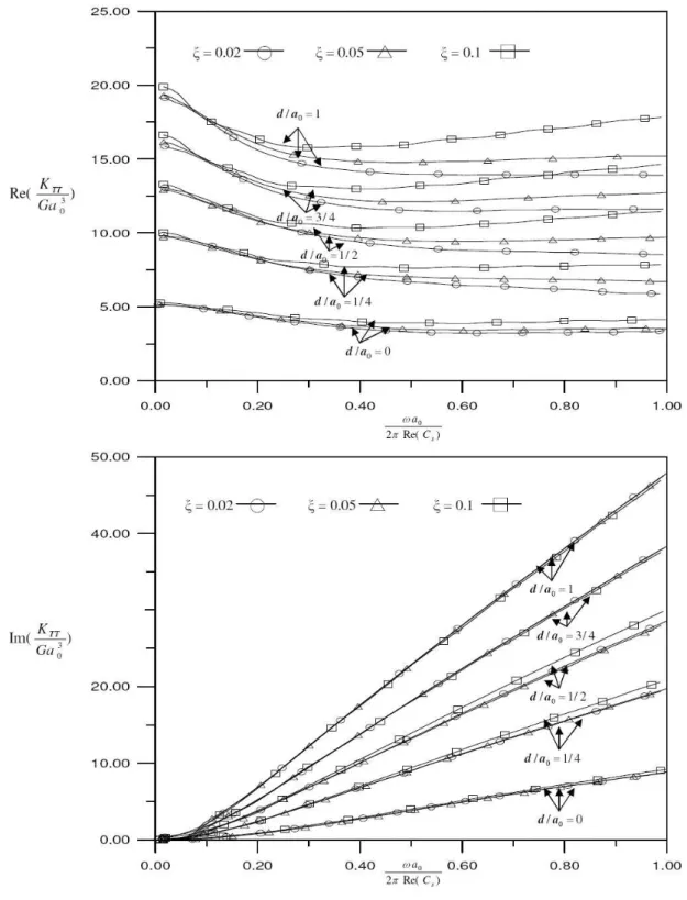
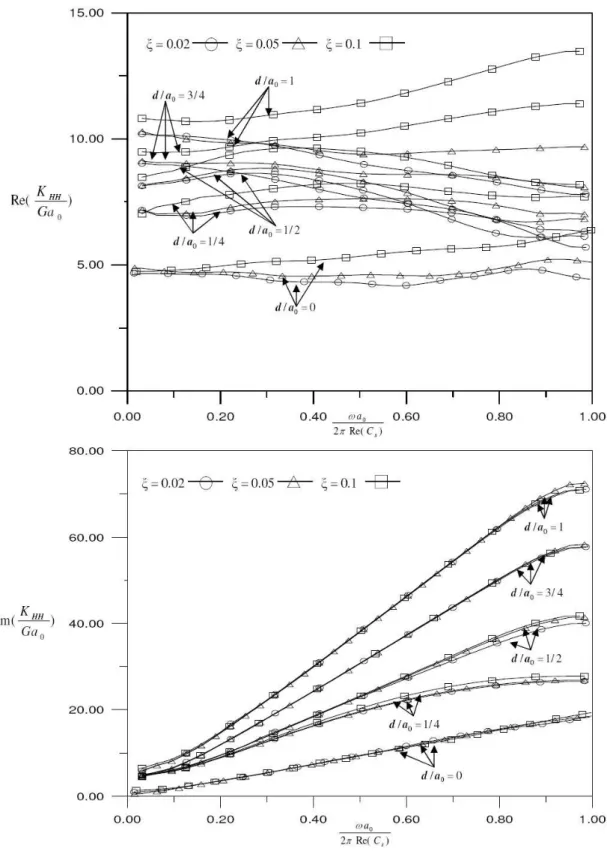
.Figs. 4~8 show the simulated numerical results of non-dimensionalized torsional, vertical, horizon-tal, coupling and rocking impedances respectively for circular foundation embedded in half-space
medium with embedded depths
d
a
0=
0
,1
4
,1
2
,3
4
, and1
. In the figures, the results forξ
=
0.02
are calculated by using
a
0L
=
0.08
, the results forξ
=
0.05
are calculated by usinga
0L
=
0.1
andthe results for
ξ
=
0.1
are calculated by usinga
0L
=
0.15
. From these figures, one can observe thatLatin American Journal of Solids and Structures 10(2013) 1225 – 1241
Figure 3 Comparison of non-dimensionalized vertical impedance with Liou’s results for
d a
0
Latin American Journal of Solids and Structures 10(2013) 1225 – 1241
Latin American Journal of Solids and Structures 10(2013) 1225 – 1241
Latin American Journal of Solids and Structures 10(2013) 1225 – 1241
Latin American Journal of Solids and Structures 10(2013) 1225 – 1241
Latin American Journal of Solids and Structures 10(2013) 1225 – 1241
Latin American Journal of Solids and Structures 10(2013) 1225 – 1241 4 CONCLUDING REMARKS
The procedure to calculate impedance functions for foundation embedded in layered medium can be extended to calculate that for the case of half-space medium by using large thickness of layered medium. Although increasing the thickness of layered medium will give rise to the numerical prob-lem in the process of computation. One just needs to suppress the upward propagating waves for the modes with large real part of
v L
′
. In the study, calculation with quadruple precision (about 32 significant figures) is defined in computer program. This leads to that the upward propagating waves for the modes withRe(
v L
′
)
≥
25
should be suppressed. Also, to simulate the case ofhalf-space medium, the thickness of layer could be decreased, if the damping ratio is greater. For
exam-ples,
a
0L
=
0.15
for ξ=
0.1
,a
0L
=
0.1
forξ
=
0.05
, anda
0L
=
0.08
forξ
=
0.02
.Acknowledgment This work is sponsored by National Science Council of Taiwan under Contract No. NSC 98-2221-E-009-098. The support is greatly appreciated.
References
[1] Lysmer J, Kuhlemeyer RL. Finite dynamic model for infinite media. J Eng Mech Div Vol. 95, 859-877 (1969). [2] Chow YK, Smith IM. Static and Periodic infinite solid elements. Int J Num Meth in Eng Vol. 17, 503-526
(1981).
[3] S. Gupta, J. Penzien, T. W. Lin, and C. S. Yeh, `Three-dimensional Hybrid Modelling of Soil–Structure Inter-action', Earthquake Eng Struct Dyn Vol. 10, 69-87 (1982).
[4] Tzong TJ, Penzien J. 'Hybrid modelling of a single-layer half-space system in soil-structure interaction. Earth-quake Eng Struct Dyn Vol. 14, 517-530 (1986).
[5] Luco JE, Apsel RJ. On the Green’s functions for a layered half-space: Part I. Bull. seism. soc. Am. Vol. 73, 909-929 (1983).
[6] C.-H. Chen, and J. Penzien, `Dynamic Modelling of Axi-symmetric Foundations', Earthquake Eng Struct Dyn, Vol. 14, 823-840 (1986).
[7] Mita A, Luco JE. Dynamic response of a square foundation embedded in an elastic half-space. Soil Dyn Earth-quake Eng Vol. 8, 54-67 (1989).
[8] Wolf JP, Meek JW. Cone models for a soil layer on a flexible rock half-space. Earthquake Eng Struct Dyn Vol. 22, 185-193 (1993).
[9] Wolf JP, Preisig M. Dynamic stiffness of foundation embedded in layered half-space based on wave progation in cones. Earthquake Eng Struct Dyn Vol. 32, 1075-1098 (2003).
[10] Liou GS. Analytic solutions for soil-structure interaction in layered media. Earthquake Eng Struct Dyn Vol. 18, 667-686 (1989).
[11] Liou GS, Lee GC, Ketter LR. Analytic solution for dynamic loading on half-space. Journal of Engineering Mechanics ASCE Vol. 117, 1485-1495 (1991).
[12] Liou GS. Vibration of surface foundations of arbitrary shapes. Earthquake Eng Struct Dyn Vol. 20, 1115-1125 (1991).
[13] Liou GS, Chung IL. Impedance matrices for circular foundation embedded in layered medium. Soil Dyn Earth-quake Eng Vol. 29, 667-692 (2009).
[14] Sezawa K. Further studies on rayleigh waves having some azimuthal distribution. Bulletin of Earthquake Re-search Institute Vol. 6, 1-18 (1929).