Abstract
The dynamic response of functionally graded skew shell is investi-gated using a C0 finite element formulation. Reddy’s higher order
theory has been employed to perform the analysis and the volume fractions of the ceramic and metallic components are assumed to follow simple linear distribution law. The present study attempts to focus mainly on the influence of skew angle on frequency pa-rameter and displacement of shell panel with various geometries. Comprehensive numerical results are demonstrated for cylindrical, spherical and hypar shells for different boundary conditions and skew angles.The findings obtained for functionally graded skew shell panels are new and can be used as bench mark for research-ers in this field.
Key words
Skew shell, functionally graded material, finite element formula-tion, higher order shear deformation theory.
Dynamic response of functionally graded skew shell panel
1 INTRODUCTION
Due to commodious applications of functionally graded material (FGM) in various fields of engineer-ing, it enthralled the attention of many researchers worldwide. Moreover, the smooth and continuous change of mechanical properties across the preferred direction made them to occupy forefront in the material research. Understanding the vibration characteristics and dynamic behavior of members made of such materials is of prime importance from structural design point of view.
Owing to the above reasons, a large number of works have been devoted to conceive the vibration characteristics and dynamic response of functionally graded plates and shells exposed to thermo-mechanical loads. Consequently, many theories were developed to model the structure that accurately predicts its response under different loading environment. Some of the most widely adopted theories available in the scientific literature include first order shear deformation theory [26] and higher order shear deformation theory [24, 25]. In the past years, first order shear deformation theory (FSDT) which neglects the effects of transverse shear strain is used to accomplish the linear as well as non linear response of shells. For example, Zhao et al.[6] carried out static and vibration analysis of func-tionally graded cylindrical shell using element-free kp-Ritz method and found that the volume fraction exponent plays significant role in predicting the response of the shell; Kim et al. [4] presented the
G uls han Ta j M. N. A* An up am Ch ak ra ba rti
Departmentof Civil Engineering, IndianInstituteof Technology,
Roorkee-247 667, India.
Received 03 Dec 2012 In revisedform 01 Mar 2013
Latin American Journal of Solids and Structures 10(2013) 1243 – 1266
nonlinear analysis of FGM plates and shells using analytical solution and assumes the properties in terms of volume fraction exponent that follows sigmoid function; Arciniega and Reddy [3] presented a tensor based finite element formulation for large deformation analysis of FGM shells; and Reddy and Chin [10] examined the dynamic response of functionally graded plates and shells under thermo-mechanical environment. But the use of FSDT depends on the shear correction factor which is the cumbersome one to decide. Moreover, the theory may not be accurate in case of thick shells.
To explicate the shortcomings of the first order shear deformation theory many higher order shear deformation theories (HSDT) were developed in due course of time. It is noteworthy to mention that, Reddy’s higher order shear deformation theory [24] is the most widely implemented by many research-ers, where the realistic parabolic variation of transverse shear strain has been taken into account to eliminate the use of shear correction factor. Here, we cite the papers where the higher order theory [24]is successfully implemented with some analytical tools. Yang and Shen [18] analyzed the effect of thermal field on free and forced vibration analysis of functionally graded plates that combines the Reddy’s higher order shear deformation plate theory with Galerkin technique. The plates with proper-ties in between ceramic and metal components do not show the intermediate response, when the prop-erties are considered as temperature dependent. Static and dynamic response of functionally graded plates using meshless local petrov-Galerkin approach in conjunction with higher order theory has been done by Qian et al.[19]. Mori-Tanaka method that includes interactions between various elastic con-stants is used to estimate the properties of the functionally graded plate. Neves et al. [14] extended the Carrera’s unified formulation to perform vibration analysis of cylindrical shells. Two cases of trans-verse displacement (constant transtrans-verse displacement and quadratic variation with thickness co-ordinate) are considered to determine the frequency parameter of the cylindrical shell panels. Isvandzibaei and Moarrefzadeh[5] performed the free vibration analysis of FGM shells and influence of different parameters on frequency characteristics of shell are discussed briefly. Yang and Shen[15] ex-amined the free vibration and stability analysis of FGM cylindrical shell panels under thermal and mechanical loads. Reddy’s higher order theory, Galerkin technique and Blotin’s method are applied to study the response of the shell panels under static and periodic loads. Setareh and Isvandzibaei[8] stud-ied the vibration characteristics of functionally graded cylindrical shell using Reddy’s higher order shear deformation theory. Influence of constituent volume fraction on frequency parameter was stud-ied using Nickel and stainless steel shell panels. Pradyumna and Bandyopadhyay[13] located the un-stable regions in functionally graded shell panels with different geometry (cylindrical, spherical, hypar and conical) using finite element formulation.
tempera-Latin American Journal of Solids and Structures 10(2013) 1243 – 1266 ture within a fraction of seconds are encountered. Despite of high cost of this material which is consid-ered as a drawback, proper design and tailoring of such material to suit different requirement made them to stand in the row of advanced materials.
To date, vibration and dynamic solution of functionally graded shell panels are limited to rectangu-lar plan form only. Hence, an attempt is made to fill the apparent void exists in the literature by pre-senting the finite element solution to non rectangular plan form such as skew shells which have wide range of applications in modern construction industry. Reddy’s higher order shear deformation theory [24] which satisfies the condition of zero transverse shear stress at top and bottom of the shell is im-plemented. The formulation also incorporates the term for twist curvature (1/Rxy) which plays a vital
role to analyze the special forms like hypar shell, which is not yet done in any other formulation that incorporates Reddy’s higher order theory. The present study is divided into two parts. The first part gives deep insight about the vibration characteristics of various forms of functionally graded skew shells (cylindrical, spherical and hypar) by incorporating different parameters such as skew angle (α), thickness ratio (a/h), curvature ratio (R/a) and boundary conditions (simply supported and clamped). In the second part, dynamic response of skew shell is performed using Newmark integration scheme [16]. It is anticipated that the present results paves the way for researchers who are involved in the area of functionally graded skew shells.
2 MODELING AND FORMULATION
2.1 Shell geometry
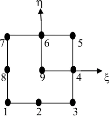
A shell element having skew boundary with Cartesian coordinate system is depicted in Fig.1. The mid surface of the shell is assumed as origin for the material coordinate system. The top surface of the shell (z=+h/2) is rich in ceramic content, whereas the bottom surface of the shell (z=-h/2) is rich in metal content. A nine noded isoprametric Lagrangian shell element (Fig. 2) having seven nodal unknowns is employed to model the present shell element. For analysis of skew shells, the edges of the boundary elements are not parallel to the global axes (x, y) of the shell. Hence it is required to carry out the necessary transformation from global axes to local axes by using nodal transformation matrix [T].For the shell finite element used in the present study the following transformation matrix [T]is utilized.
[T]=
cos
α
−sinα
0 0 0 0 0sin
α
cosα
0 0 0 0 00 0 1 0 0 0 0
0 0 0 cos
α
−sinα
0 00 0 0 sin
α
cosα
0 00 0 0 0 0 cos
α
−sinα
0 0 0 0 0 sin
α
cosα
⎛
⎝ ⎜ ⎜ ⎜ ⎜ ⎜ ⎜ ⎜ ⎜
⎞
⎠ ⎟ ⎟ ⎟ ⎟ ⎟ ⎟ ⎟ ⎟
(1)
Latin American Journal of Solids and Structures 10(2013) 1243 – 1266
z=4 c abxy+
cx a +
cy
b (2)
Figure 1 Plan view of FGM skew shell.
Figure 2 IsoparametricLagrangian element in natural co-ordinate system.
2.2 Effective properties of shell
Due to the dissimilarity of material properties along certain direction, it is necessary to evaluate the properties accurately using suitable method. Different schemes were proposed in the literature and some of them are: three phase model of Frohlich and Sack [20]; self consistent scheme [21]; Mori-Tanaka technique [22]; mean field approach [23]; Voigt method; and the representative volume ele-ment. Most widely adopted methods in the literature are Mori-Tanaka technique and Voigt method. In the present study Voigt method is employed to estimate the effective properties, such as, Young’s modulus (E), Poisson’s ratio (γ) and mass density (ρ) of the shell panel as a function of position. Based on the linear distribution law, effective properties of the shell constituents (E, γ and ρ) are expressed in terms of volume fraction of the ceramic and metal content as mentioned below.
a
y’
y
x, x’
b
α
1 2 3
8 9 4
ξ
7 6 5
Latin American Journal of Solids and Structures 10(2013) 1243 – 1266 E(z)= E
t−Eb
{
}
hz +12 ⎛ ⎝⎜ ⎞ ⎠⎟ n +E b
γ(z)= γ
t−γb
{
}
hz+12 ⎛ ⎝⎜ ⎞ ⎠⎟ n c
+γb
ρ(z)=(ρ
t−ρb)
z h+ 1 2 ⎛ ⎝⎜ ⎞ ⎠⎟ n
+ρb
(3)
where the subscripts “t” and “b” refers to the top and bottom of the surface of the shell respectively, n is the non-negative key parameter that describes the optimum distribution of constituents along the thickness direction of the shell. It takes the value between zero and infinity (i.e., zero corresponds to ceramic portion and infinity corresponds to metal portion). Since the variation of Poisson’s ratio is negligible, it is assumed as constant in the present analysis.
The constitutive relationship of functionally graded shell may be written as,
σxx σyy σyz σxz σxy ⎧ ⎨ ⎪ ⎪ ⎪ ⎩ ⎪ ⎪ ⎪ ⎫ ⎬ ⎪ ⎪ ⎪ ⎭ ⎪ ⎪ ⎪ =
Q11 Q12 0 0 0
Q21 Q22 0 0 0
0 0 Q
33 0 0
0 0 0 Q
44 0
0 0 0 0 Q
55 ⎡ ⎣ ⎢ ⎢ ⎢ ⎢ ⎢ ⎢ ⎢ ⎤ ⎦ ⎥ ⎥ ⎥ ⎥ ⎥ ⎥ ⎥ εxx εyy γyz γxz γxy ⎧ ⎨ ⎪ ⎪ ⎪ ⎩ ⎪ ⎪ ⎪ ⎫ ⎬ ⎪ ⎪ ⎪ ⎭ ⎪ ⎪ ⎪ (4)
where Qij contains the terms elastic moduli (E) and Poisson’s ratio (γ), in which E alone is the
func-tion of depth as given below.
Q11=Q22= E(z)
1−γ2,Q12 =Q21=
γE(z)
1−γ2 , Q44=Q55=
E(z)
2(1+γ)
Here, the Young’s modulus (E) and Poisson’s ratio (γ) of the panel at any height (z) of the shell can
be easily estimated by using Equation (3). It should be noted that, the term
z
h
+
1
2
⎛
⎝⎜
⎞
⎠⎟
ninvolving in
Equation (3) implies the volume fraction of the ceramic content (Vc) present in the panel considered.
Further, the correlation between the volume fraction of ceramic (Vc) and metal (Vm) components is given by the relation Vc+Vm=1.0.
2.3 Displacement field
Latin American Journal of Solids and Structures 10(2013) 1243 – 1266
those in the first-order shear deformation theory [24]. Also, the theory leads to the parabolic distribu-tion of transverse shear stresses and therefore the need of shear correcdistribu-tion co-efficient could be avoid-ed. According to Reddy’s higher order shear deformation theory [24], the in-plane displacements (u and v) and transverse displacement (w) are expressed in terms of corresponding displacements at the mid surface (uo, vo and wo) by the following expression.
2 3 0 2 3 0 0
( , , )
( , )
( , , )
( , , )
( , , )
( , , )
( , , )
( , , )
( , , )
( , , )
( , )
( , )
x x x
y y y
u x y z
u x y
z
x y z
z
x y z
z
x y z
v x y z
v x y z
z
x y z
z
x y z
z
x y z
w x y
w x y
θ
ξ
ζ
θ
ξ
ζ
=
+
+
+
=
+
+
+
=
(5)
where u, v and w are the displacements of any general point in the shell. The parameters u0, v0and w0
are the displacements of points which are in the mid-surface (i.e., reference surface) of the shell and θx,
θy are the bending rotations defined at the mid-surface about the y and x axes respectively. ξx, ξy, ζx and ζy are higher order terms appears in Taylor’s series expansion and solved by the condition of zero transverse shear stains (γxz(x,y,±h/2) = γyz(x,y,±h/2)=0) at the top and bottom of the shell surface.
Thus, incorporation of the above condition in Equation (5) leads to the expression for unknown higher order terms (ξx, ξy, ζx and ζy). Finally, by substituting the values of unknown higher order terms (ξx, ξy, ζx and ζy) in Equation (5) and rearranging all the terms that appears in the displacement field (u and v), the following final expression may be obtained.
3 0 2 3 0 2 0
4
( , , )
( , , )
( , , )
3
4
( , , )
( , , )
( , , )
3
( , )
( , )
x x y yz
w
u x y z
u x y z
z
x y z
h
x
z
w
v x y z
v x y z
z
x y z
h
y
w x y
w x y
θ
θ
θ
θ
∂
⎛
⎞
=
+
−
⎜
+
⎟
∂
⎝
⎠
⎛
∂
⎞
=
+
−
⎜
+
⎟
∂
⎝
⎠
=
(6)In Equation (6), it is to be noted that the in-plane displacement field u and v invites the problem of C1 continuity by the presence of second order derivatives in the strain part. The problem of choosing C1 elements are well known due to its practical applications. In order to overcome the problem of C1 continuity requirement at the time of finite element implementation the terms involving derivatives of
transverse displacement are treated as separate field variables. i.e., ψ
x
*
= θx+
∂w
∂x
⎛ ⎝⎜
⎞
⎠⎟ and ψy *
= θy+∂w
∂y ⎛ ⎝⎜
⎞ ⎠⎟ Hence by above substitution, the final in-plane displacement fields (u and v) for skew shell with the co-ordinate axes (x’, y’, z’) can be modified as
u(x',y',z')=uo(x',y',z')+zθx 1−4z
2
3h2
⎛ ⎝⎜
⎞ ⎠⎟−
4z3
3h2ψx *
v(x',y',z')=vo(x',y',z')+zθy 1−4z
2
3h2
⎛ ⎝⎜
⎞ ⎠⎟−
4z3
3h2ψy *
Latin American Journal of Solids and Structures 10(2013) 1243 – 1266 Hence, the basic field variables interpreted in the present study are u0, v0, w0, θx, θy, ψx* and ψy* for
each node thus forming a total of 63 nodal unknowns for the element.
2.4 Mathematical formulation
2.4.1 Strain displacement relation
All the formulation in the present study is confined to linear elastic behavior with small displacements and hence small strains. The linear strain- displacement relations according to Sander’s shell theory are
εx=∂u ∂x+
w Rx
εy=∂v ∂y+
w Ry
γxy=∂u ∂y+
∂v ∂x+
2w Rxy
γxz =∂∂u z+
∂w ∂x −
C1u Rx −
C1v Rxy
γyz=∂v
∂z+ ∂w ∂y−
C1v Rx −
C1u Rxy
(8)
Rx, Ry represents the radii of curvature in the x and y directions respectively and Rxy is the twist radii
of curvature. C1 is the tracer that helps to reduce the approximation in to Love’s shell theory and it is taken as unity in the present formulation. To combine equation (6), (7) and (8), the strain terms may be re-written as
ε
x=
ε
xo+
z
1
−
4
z
2
3
h
2⎛
⎝⎜
⎞
⎠⎟
k
x−
4
z
33
h
2k
x*
ε
y=
ε
yo+
z
1
−
4
z
2
3
h
2⎛
⎝⎜
⎞
⎠⎟
k
y−
4
z
33
h
2k
y*
γ
xy=
γ
xyo+
z
1
−
4
z
2
3
h
2⎛
⎝⎜
⎞
⎠⎟
k
xy−
4
z
33
h
2k
xy*
γ
yz=
φ
y+
z
1
−
4
z
2
3
h
2⎛
⎝⎜
⎞
⎠⎟
k
yz−
4
z
33
h
2k
yz*
−
4
z
2
h
2k
yz **γ
xz=
φ
x+
z
1
−
4
z
2
3
h
2⎛
⎝⎜
⎞
⎠⎟
k
xz−
4
z
33
h
2k
xz*
−
4
z
2
h
2k
xz **Latin American Journal of Solids and Structures 10(2013) 1243 – 1266
where the different terms involved in the above equation are defined in the following fashion.
εxo,εyo,γxyo
{
}
= ∂uo∂x + wo Rx,
∂vo ∂y +
wo Ry,
∂uo ∂y +
∂vo ∂x +
2wo Rxy ⎧ ⎨ ⎪ ⎩⎪ ⎫ ⎬ ⎪ ⎭⎪
φx,φy
{
}
= ∂u∂z +∂w∂x −C1uRx − C1v
Rxy , ∂w
∂y +θy−
C1vo
Rx − C1uo
Rxy ⎧ ⎨ ⎪ ⎩⎪ ⎫ ⎬ ⎪ ⎭⎪
kx,ky,kxy,kx* ,ky*
,kxy*
{
}
= ∂θx∂x , ∂θy
∂y , ∂θx
∂y + ∂θy
∂x , ∂ψx*
∂x , ∂ψ*y
∂y , ∂ψx*
∂y + ∂ψy*
∂x ⎧ ⎨ ⎪ ⎩⎪ ⎫ ⎬ ⎪ ⎭⎪
kxz,kyz,kxz*,kyz*,kxz**,kyz**
{
}
=−C1θx
Rx −C1
θy
Rxy,−C1
θy
Ry −C1
θx
Rxy,−C1
ψx* Rx −C1
ψy* Rxy,
−C1ψy * Ry −C1
ψx*
Rxy,θx+ψx
*
,θy+ψy* ⎧ ⎨ ⎪ ⎪ ⎩ ⎪ ⎪ ⎫ ⎬ ⎪ ⎪ ⎭ ⎪ ⎪
2.4.2 Free vibration analysis
The acceleration at any point within the element may be expressed in terms of the mid surface param-eters (u0, v0 and w0) as
f
{ }
..
=
∂
2
∂
t
2f
−
⎧
⎨
⎩
⎫
⎬
⎭
=
−
ω
2u
0v
0w
0⎧
⎨
⎪
⎩
⎪
⎫
⎬
⎪
⎭
⎪
=
−
ω
2⎡⎣ ⎤⎦
F
{ }
f
(10)Where
{ }
f
=
u
0v
0w
0θ
xθ
yψ
x*
ψ
y*⎡
⎣
⎤
⎦
T
and the matrix [F] contains the terms involving z and h as
ex-pressed below.
F
⎡⎣ ⎤⎦
=
1
0
0
z
0
−
4
z
33
h
20
0
1
0
0
z
0
−
4
z
33
h
20
0
1
0
0
0
0
⎡
⎣
⎢
⎢
⎢
⎢
⎢
⎢
⎢
⎢
⎤
⎦
⎥
⎥
⎥
⎥
⎥
⎥
⎥
⎥
Again the matrix {f} is decoupled into matrix [C] that contains the interpolation functions (Ni) and global displacement vector {X}.
f
Latin American Journal of Solids and Structures 10(2013) 1243 – 1266 where the global displacement vector {X} contains the nodal unknowns for all the nine nodes and thus forming the matrix of order 63x1. i.e.,
{ }
X = uiviwiθxiθyiψxi*ψyi
*
⎡
⎣ ⎤⎦
, where
i=1-9.
The shape functions in [C] associated with the present nine noded Lagrangian element are as given below.
Finally utilizing the Equations (10) and (11), the mass matrix of an element may be expressed as,
m
⎡⎣ ⎤⎦
=
⎡⎣ ⎤⎦
C
TL
⎡⎣ ⎤⎦
⎡⎣ ⎤⎦
C
dA
A∫∫
(12)
where matrix [L]can be written as
L
⎡⎣ ⎤⎦
=
ρ
⎡⎣ ⎤⎦
F
T
F
⎡⎣ ⎤⎦
dz
z
∫
(13)Where ρ is the density of the material estimated from Equation (1). Hence the governing equation for free vibration analysis becomes,
K
⎡⎣ ⎤⎦ −
ω
2⎡⎣ ⎤⎦
M
(
)
{ }
X
=
{ }
0
(14)where [M], [K] and ω are global mass matrix, global stiffness matrix and frequency parameter. The right hand side of the above equation zero represents the problem of free vibration analysis. Eigen value algorithm is utilized to extract the mode shapes of the shell panel.
2.5 Dynamic Response
For the problem of forced vibration Equation (14) is modified to incorporate damping matrix [C] and the force vector {q} at the right hand side. Hence the governing equation for forced vibration analysis becomes,
[
M
]
U
..
+
[
C
]
U
.
+
[
K
]
U
=
{
q
}
(15)(
)(
)
(
)(
)
(
)(
)
(
)(
)
(
)
(
)
(
)
(
)
(
)
(
)
(
)
(
)
(
)(
)
1 2 3
2 2
4 5 6
2 2 2 2
7 8 9
1 1 1
1 1 , 1 1 , 1 1 ,
4 4 4
1 1 1
1 1 , 1 1 , 1 1 ,
4 2 2
1 1
1 1 , 1 1 , 1 1 .
2 2
N N N
N N N
N N N
ξ η ξη ξ η ξη ξ η ξη
ξ η ξη ξ η η ξ η ξ
ξ η η ξ η ξ ξ η
= − − = + − = + +
= − + =− − − =− + −
Latin American Journal of Solids and Structures 10(2013) 1243 – 1266
Where, [M]and [K] represent the global mass matrix and stiffness matrix respectively.[C] is the Rayleigh damping matrix and it is considered as below.
[
C
]
=
α
[
M
]
+
β
[
K
]
(16)In the above form, α and β are constants to be determined from two given damping ratios corre-sponding to two unequal frequencies of vibration. {q}appearing in Equation (12) is the dynamic pres-sure applied on the top of the shell. It is given by,
q x
(
,
y
,
t
)
=
q
0F
(
t
)
(17)Here, q0 is the maximum amplitude and F(t)is a dynamic load shape function of time domain. In the present analysis F(t) is taken as unity for the case of suddenly applied load. The extension of the linear acceleration method known as Newmark integration method [16] is used to obtain the transient response of the system. A step-by-step procedure for the problem of dynamic response is summarized below.
1. For the problem under consideration the stiffness matrix [K], mass matrix [M] and damping matrix [C]are formed as an initial step.
2. The magnitude of displacement
( )
U , velocity U.
⎛ ⎝⎜
⎞
⎠⎟and acceleration U ..
⎛ ⎝⎜
⎞
⎠⎟ at time t=0 are initial-ized.
3. The time step ∆t is chosen, and parameters α and β are to be determined from damping ratios that corresponds to two unequal natural frequencies obtained from free vibration analysis. 4. The co-efficients are determined from the expression given below.
a
o=
1
αΔt2; a
1= β αΔt;
a 2 =
1
αΔt; a
3=
1
2α −1;a4= β
α −1;
a 5=
Δt
2
β
α −2
⎛ ⎝⎜
⎞
⎠⎟;a6=Δt(1−β);a7=δΔt
(18)
5. Effective stiffness matrix [K’] is formed as
[K’]=[K]+a0[M]+a1[C] (19)
6. The above formed effective stiffness matrix [K’] is triangularized. Then, effective loads [R’] are calculated at time t+∆t.
Latin American Journal of Solids and Structures 10(2013) 1243 – 1266
3 DISCUSSION ON NUMERICAL PROBLEMS
This section is broken down into three parts: (1) The accuracy and efficiency of the present finite element formulation are validated with the existing literature data for free and forced vibration analy-sis; (2) Vibration analysis is done for skew shells with cylindrical (Rx=R, Ry=Rxy=∞), spherical
(Rx=Ry=R, Rxy=∞) and hypar (Rx=Ry=∞) geometry; and (3) Transient response of the cylindrical
skew shell is studied under suddenly applied dynamic pressure. Properties of the ceramic and metal constituents adopted to perform these analyses are mentioned below.
FGM I: Silicon Nitride (Si3N4)/ Stainless steel (SUS304): Ec= 322.27GPa, Em=207.78GPa, γ=0.3, ρc =2370, ρm = 8166. FGM II: Silicon carbide (SiC)/ Aluminium (Al):
Ec= 427GPa, Em=70 GPa, γc=0.17, γ=0.3, ρc =3210, ρm = 2707.
All the results presented herein are in dimensional forms and following are the different non-dimensional parameters implemented in the study.
Frequency: Ω=Ωa2
12ρm(1−γ
2
) E
mh
2
Displacement:
w
(
a
/ 2,
b
/ 2)
=
wE
mh
q
oa
2Time:
t
=
t
E
ma
2ρ
m
Axial stresses: σ
xx(a/ 2,b/ 2)=
σ
xxh
2
q a2
3.1 Free vibration analysis- validation study
Latin American Journal of Solids and Structures 10(2013) 1243 – 1266
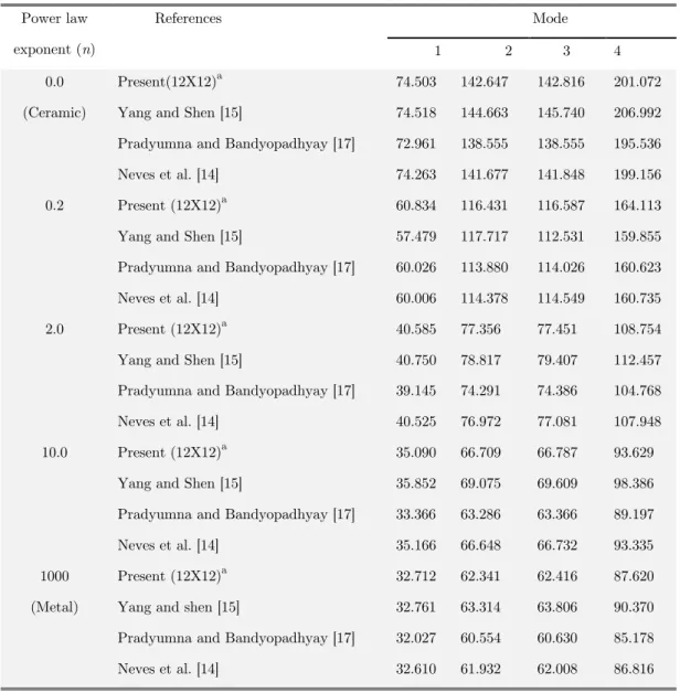
Table 1 Vibration modes of square cylindrical shell (FGM I) with clamped boundary condition.
Power law exponent (n)
References Mode
1 2 3 4
0.0 (Ceramic)
Present(12X12)a 74.503 142.647 142.816 201.072 Yang and Shen [15] 74.518 144.663 145.740 206.992 Pradyumna and Bandyopadhyay [17] 72.961 138.555 138.555 195.536 Neves et al. [14] 74.263 141.677 141.848 199.156 0.2 Present (12X12)a 60.834 116.431 116.587 164.113 Yang and Shen [15] 57.479 117.717 112.531 159.855 Pradyumna and Bandyopadhyay [17] 60.026 113.880 114.026 160.623 Neves et al. [14] 60.006 114.378 114.549 160.735 2.0 Present (12X12)a 40.585 77.356 77.451 108.754 Yang and Shen [15] 40.750 78.817 79.407 112.457 Pradyumna and Bandyopadhyay [17] 39.145 74.291 74.386 104.768 Neves et al. [14] 40.525 76.972 77.081 107.948 10.0 Present (12X12)a 35.090 66.709 66.787 93.629
Yang and Shen [15] 35.852 69.075 69.609 98.386 Pradyumna and Bandyopadhyay [17] 33.366 63.286 63.366 89.197 Neves et al. [14] 35.166 66.648 66.732 93.335 1000
(Metal)
Present (12X12)a 32.712 62.341 62.416 87.620 Yang and shen [15] 32.761 63.314 63.806 90.370 Pradyumna and Bandyopadhyay [17] 32.027 60.554 60.630 85.178 Neves et al. [14] 32.610 61.932 62.008 86.816
a indicates mesh size
Latin American Journal of Solids and Structures 10(2013) 1243 – 1266 3.2. Dynamic response - validation study
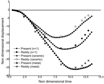
The above formulation is extended to study the transient response of shell panel having different skew angles (α) and power law exponent (n). Validation part considers the square simply supported FGM (Al/Zr02) plate with geometric properties a =b =0.2m and h=0.01m. The corresponding material properties are: Ec= 151GPa, γc =0.3, ρc =3000 kg/m3 for Zirconia (Zr02) and Em=70GPa, γm =0.3, ρm = 2707 kg/m3 for Aluminium (Al). The plate is subjected to a uniformly distributed load of 106 N/m2 in upward direction and time step of 0.00001s is considered. Fig.3 reveals the comparison of present results with those of Praveen and Reddy [2] which is based on first order shear deformation theory [35, 36]. The results are compared for selected values of power law exponent n = 0.0, 1.0 and 1000, again a good agreement between the results is observed for all the values of n considered.
Present (n=1) Reddy (n=1) Present (ceramic) Reddy (ceramic) Present (metal) Reddy (metal)
0.0 2.5 5.0 7.5 10.0 12.5 15.0 -40
-35 -30 -25 -20 -15 -10 -5 0 5
No
n di
mensi
on
al
di
spl
ace
ment
Non dimensional time
Figure 3 Transient response of plate (FGM I, simply supported) –Validation study.
3.3 New results
After examining the effectiveness of the present formulation, the study is extended to perform the vi-bration and dynamic analysis of FGM skew shells. The different shell forms such as cylindrical, spheri-cal and hypar are considered to generate new results.
3.3.1 Skew cylindrical shell with various thickness ratios (a/h)
Latin American Journal of Solids and Structures 10(2013) 1243 – 1266
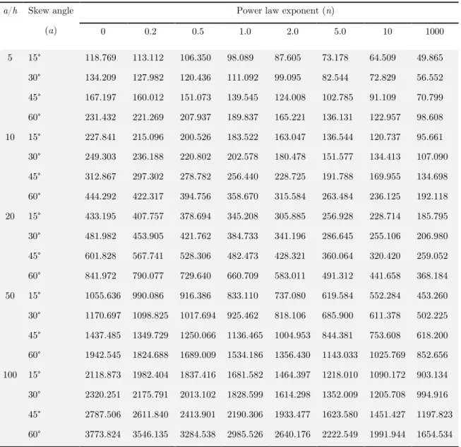
(nearly about 1.5-1.7 times). For thick shells (a/h =5.0 and 10.0) with clamped boundary and skew angle 30°, the deviation in results is found from other cases (a/h =20.0, 50.0 and 100). Therefore, it can be inferred that the present model will not accurately predict the frequency in case of thick clamped cylindrical skew shell predominantly for skew angle 30°. Fundamental frequency mode of simply supported cylindrical skew shell with R/a=5.0 and different values of power law exponent (n) are established in Table 3. As estimated, the clamped skew shell establish higher frequency compared to simply supported shell, due to high stiffness.
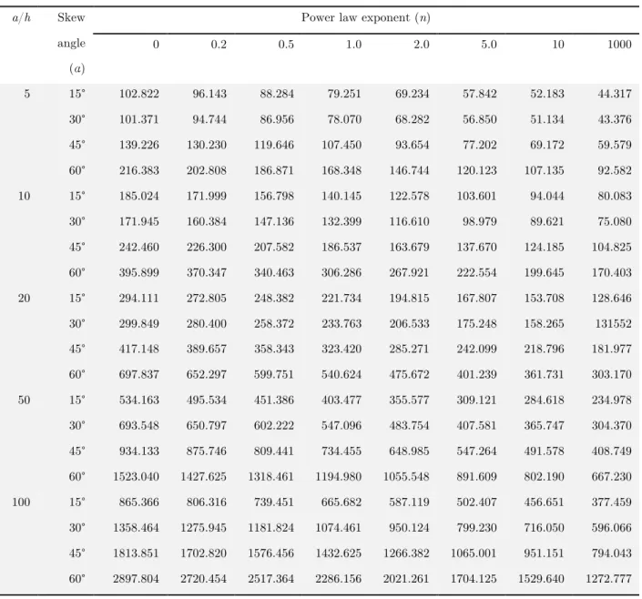
Table 2 Non dimensional frequencies of square cylindrical shell (FGM II) with clamped boundary condition (R/a=5.0).
a/h Skew angle (α)
Power law exponent (n)
0 0.2 0.5 1.0 2.0 5.0 10 1000
Latin American Journal of Solids and Structures 10(2013) 1243 – 1266
Table 3 Non dimensional frequencies of square cylindrical shell (FGM II) with simply supported boundary condition (R/a=5.0).
3.3.2 Skew spherical shell with various thickness ratios (a/h)
The fundamental frequency of square spherical shell with clamped and simply supported boundary condition is demonstrated in Table 4 and Table 5, respectively. Shell panel with R/a=5.0 and several values of thickness ratio (a/h) are considered. The observations drawn for spherical shell are similar to those for cylindrical shells, except that high magnitude of frequency is reported in case of spherical shell.
a/h Skew angle (α)
Power law exponent (n)
0 0.2 0.5 1.0 2.0 5.0 10 1000
5 15° 53.388 49.875 45.871 41.374 36.412 30.693 27.621 22.951 30° 82.586 76.946 70.400 62.981 54.933 45.898 41.425 35.264 45° 111.264 104.962 97.497 88.578 77.863 64.833 58.034 47.404 60° 150.283 143.009 134.086 122.837 108.356 90.098 80.542 64.179 10 15° 96.784 90.395 83.172 75.010 66.196 55.974 50.420 41.895 30° 138.752 128.777 117.872 105.667 92.876 79.113 71.918 60.337 45° 213.801 200.471 185.021 167.208 147.081 123.628 110.968 91.572 60° 294.951 278.867 260.227 238.182 211.245 176.641 156.895 125.992 20 15° 175.069 162.844 148.822 113.269 117.244 100.701 91.625 76.290
Latin American Journal of Solids and Structures 10(2013) 1243 – 1266
Table 4 Non dimensional frequencies of square spherical shell (FGM II) with clamped boundary condition (R/a=5.0).
a/h Skew angle (α)
Power law exponent (n)
0 0.2 0.5 1.0 2.0 5.0 10 1000
Latin American Journal of Solids and Structures 10(2013) 1243 – 1266
Table 5 Non dimensional frequencies of square spherical shell (FGM II) with simply supported boundary condition (R/a=5.0).
3.3.3 Skew cylindrical and spherical shell with several curvature ratios (R/a)
This example refers to the square cylindrical and spherical shell with a/h=10, power law exponent n =1.0, having simply supported and clamped boundary condition. Various values of R/a ratio (0.2, 0.5, 5.0, 10.0, and 50.0) are selected to perform the study. Influence of R/a ratio on frequency parameter for cylindrical, spherical skew shell with simply supported and clamped boundary condition are inves-tigated in Fig.4 and Fig.5, respectively. It should be noted that, R=1/radius of curvature is adopted in this case. Up to a certain value of R/a (i.e.,(R/a)=2.0), it endures decline tendency in hasty manner, after which it converges to a constant for all the values of R/a considered. The shell with clamped boundary confirms elevated frequency compared to shell with simply supported boundary.
Further-a/h Skew angle (α)
Power law exponent (n)
0 0.2 0.5 1.0 2.0 5.0 10 1000
5 15° 70.435 67.100 62.922 58.004 52.453 44.708 39.451 29.896 30° 91.233 87.173 82.240 76.273 68.905 58.169 51.061 38.501 45° 116.113 110.950 104.671 96.866 86.682 72.269 63.682 49.182 60° 151.826 145.167 136.969 126.514 112.545 93.545 82.937 64.716 10 15° 124.097 117.594 109.868 100.849 90.303 76.392 67.616 52.937 30° 168.884 160.016 149.738 137.711 123.203 103.687 91.410 71.268 45° 221.471 209.943 196.516 180.595 161.039 134.843 119.027 93.741 60° 296.372 281.168 263.429 242.203 215.706 180.290 159.414 126.318 20 15° 231.618 218.506 203.273 185.670 165.132 139.185 123.701 99.292
Latin American Journal of Solids and Structures 10(2013) 1243 – 1266
more, spherical skew shell authenticates its superiority over cylindrical skew shell irrespective of the value of R/a considered.
Figure 4 Influence of R/a ratio on non dimensional frequencies of cylindrical skew shell (FGM II, n =1.0, a/h=10).
Figure 5Influence of R/a ratio on non dimensional frequencies of spherical skew shell (FGM II, n =1.0, a/h=10)
3.3.4 Skew hypar shell with various c/a ratios
In this example, the term c/a is used as an indicator of the twist curvature of hypar shell. Effect of c/a ratio on frequency parameter for simply supported and clamped boundary conditions having geometric properties a/ h=10.0 and power law exponent (n)=1.0 is illustrated in Table 6. When the c/a ratio improves from 0.0 to 0.3, the frequency of the shell increases for all the skew angles (α) considered. As anticipated, shell with clamped boundary shows more frequency than shell with simply supported boundary.
0 10 20 30 40 50
50 100 150 200 250 300 F requ en cy pa ramet er R/a 15 degrees 30 degrees 45 degrees 60 degrees Boundary: Clamped
0 10 20 30 40 50
0 50 100 150 200 F requ en cy pa ramet er R/a 15 degrees 30 degrees 45 degrees 60 degrees Boundary: simply supported
0 10 20 30 40 50
0 40 80 120 160 200 240 280 320 360 F requ en cy pa ramet er R/a 15 degrees 30 degrees 45 degrees 60 degrees Boundary: clamped
Latin American Journal of Solids and Structures 10(2013) 1243 – 1266
Table 6 Non-dimensional frequencies of square hypar skew shell (FGM II, a/h =10.0, n =1.0)
3.3.5 Cylindrical skew shell subjected to dynamic pressure
In order to generate new results for dynamic response of cylindrical (FGM I) skew shell the effects of different parameters such as skew angle (α), volume fraction index (n), shell geometry (cylindrical and spherical) and aspect ratio (b/a) are considered and the results are presented in the form of Figures (Figs. 6-9).Simply supported boundary condition is adopted to perform all the problems related to dynamic response of the panel and the displacement at the center of the shell is shown in all the fig-ures. As a first illustration, in order to study the consequence of change of skew angle on the central displacement, cylindrical shell with a/h=10.0 is used and depicted in Fig.6. In this example, the value of the skew angle ranges from 15° to 60° and a linear variation of n (n=1.0) is considered. Cylindrical shell with skew angle 30° endures the maximum displacement; and the minimum displacement is ob-served for skew angle 60°. Hence it is concluded that, an increase in skew angle contributes more stiff-ness to the shell under consideration thus recording minimum displacement at the center of the shell. Fig.7 reveals the consequence of aspect ratio (b/a) on central displacement component for cylindrical shell with skew angle (α) =15°. Four different cases of aspect ratio (b/a= 0.5, 1.0, 2.0 and 5.0) and skew angle 15 °are chosen to perform the study. Smaller aspect ratio (b/a=0.5) ensures maximum central displacement while the minimum value is observed for the value of b/a=5.0. Shell with aspect ratio b/a=5.0 exhibits negligible displacement is also observed in Fig.7. In Fig. 8, skew shell (α =15°) with two different geometry namely, cylindrical and spherical shells are considered for the study. As expected, the spherical shell report less deflection compared to cylindrical shell, thus ensuring its high stiffness. Next, the power law exponent (n) is varied from ceramic (n=0) to metal segment (n=very high value), to study its influence on transient response of cylindrical skew shell as demonstrated in Fig. 9. Shell with pure metal (n=very high value) gives maximum displacement, followed by composite shell and pure ceramic shell (n=0.0). Dominance of stiffness effect offered by pure ceramic shell may be the possible cause for the above observation. At the end, variation of axial stresses over a period of time for cylindrical shell having skew angle 0° to 60° is also studied. The shell with skew angle (α) 30° gives maximum axial stress compared to other skew shells.
Boundary condition Skew angle (α)
c/a
0 0.05 0.1 0.15 0.2 0.25 0.3
Simply supported
15° 37.085 37.130 37.263 37.484 37.788 38.170 38.625 30° 60.418 60.448 60.556 60.741 61.002 61.338 61.748 45° 100.105 100.136 100.238 100.408 100.647 100.955 101.331 60° 177.715 177.745 177.806 177.897 178.018 178.170 178.352
Clamped
Latin American Journal of Solids and Structures 10(2013) 1243 – 1266
0 3 6 9 12 15
-0.10 -0.05 0.00 0.05 0.10 0.15 0.20 0.25 0.30 0.35
No
n-di
mensi
on
al
di
spl
ace
ment
Non-dimensional time 15 deg
30 deg 45 deg 60 deg
Figure 6 Influence of skew angle (α) on the transient response of cylindrical shell (FGM I, n =1.0, a/h=10.0)
0 2 4 6 8 10 12 14 16
-0.2 0.0 0.2 0.4 0.6 0.8 1.0 1.2 1.4 1.6
No
n-di
mensi
on
al
di
spl
ace
ment
Non-dimensional time b/a=0.5 b/a=1.0 b/a=2 b/a=5
Figure 7 Effect of aspect ratio (b/a) on dynamic response of cylindrical skew shell (FGM I, α=15°, n=1.0, a/h=10.0)
Latin American Journal of Solids and Structures 10(2013) 1243 – 1266
0 3 6 9 12 15
-0.10 -0.05 0.00 0.05 0.10 0.15 0.20 0.25 0.30
No
n-di
mensi
on
al
di
spl
ace
ment
Non-dimensional time Cylindrical
Spherical
Figure 8 Influence of shell geometry on the dynamic response of cylindrical skew shell (FGM II, α=15°, n =1.0, a/h=10.0)
0 3 6 9 12 15
-0.15 -0.10 -0.05 0.00 0.05 0.10 0.15 0.20 0.25 0.30 0.35
No
n
-di
mensi
on
al
di
spl
ace
ment
Non-dimensional time n=0
n=1 n=5 n=10 n=100000
Latin American Journal of Solids and Structures 10(2013) 1243 – 1266
0 3 6 9 12 15
-0.008 -0.004 0.000 0.004 0.008
No
n-di
mensi
on
al
axi
al
st
ress
Non-dimensional time 15 degrees 30 degrees 45 degrees 60 degrees
Figure 10 Influence of non-dimensional axial stresses on the dynamic response of cylindrical skew shell (FGM II, α=15°, n =1.0, a/h =100).
4 SUMMARY
In the present paper the dynamic response of functionally graded skew shell has been studied by using a C0 finite element formulation which is developed to overcome the issue of C1 continuity associated with the present higher order shear deformation theory (HSDT). Different types of skew shell geome-tries are considered and various conclusions regarding the analysis are highlighted in the discussion section. The term for twist curvature is also included in the formulation to analyze special shell forms such as hypar shells. Based on the detailed study, the following observations are drawn regarding the free and forced vibration response of different types of functionally graded shells by varying different geometric and material parameters.
i. Skew angle: Increase in skew angle (α) exhibit higher frequency irrespective of the value of powerlaw exponent (n) considered and hence ensures minimum displacement. Also, shell with skew angle 30° gives the maximum axial stress.
ii. Shell geometry: Spherical skew shell establish better performance in vibration and transient response compared to cylindrical skew shell when boundary condition and other parameters (i.e., geometric properties and power law exponent) are kept constant.
iii. Boundary conditions: Skew shell with clamped boundary shows higher frequency than shell with simply supported boundary, due to the high rigidity in the first case.
Latin American Journal of Solids and Structures 10(2013) 1243 – 1266 The above conclusions may be helpful for the researchers affianced in analysis and design of skew shell panels, as they are reported for the first time.
References
[1] Amirhossein Nezhadi, Roslan Abdul Rahman and Amran Ayob,(2011). Transient analysis of functionally graded cylindrical shell under impulse local loads, Australian J. Basic and Applied Sciences 5(12): 757-765.
[2] Praveen, G.N., and Reddy,J.N., (1998). Nonlinear transient thermoelastic analysis of functionally graded ceramic-metal plates, Int. J. Solids and Structures 35(33): 4457-4476.
[3] Arciniega, R.A., and Reddy, J.N., (2007). Large deformation analysis of functionally graded shells, Int. J. Solids and Structures 44: 2036-2052.
[4] Ki du kim, Gilson Rescober Lomboy and Sung Cheon Han, (2008) Geometrically non-linear analysis of functionally graded material plates and shells using a four node quasi conforming shell element, J. Composite Materials 42(5): 485-511.
[5] Mohammad Reza Isvandzibaei and Ali Moarrefzadeh, (2011). Vibration two type functionally graded cylindrical shell, Int. J. Multidisciplinary Sciences and Engineering 2(8): 7-11.
[6] Zhao, Lee, Y.Y., and Liew, K.M., (2009). Thermoelastic and vibration analysis of functionally graded cylindrical shells, Int. J. Mechanical Sciences 51: 694-707.
[7] Alibeigloo, A.,Kani, A.M., and Pashaei, M.H., (2012). Elasticity solution for the free vibration analysis of function-ally graded cylindrical shell bonded to thin piezoelectric layers: Int. J. Pressure Vessels and Piping, 89: 98-111. [8] Mohammed Setareh,A., and Mohammad Reza Isvandzibaei, (2011). A finite element formulation for analysis of
functionally graded plates and shells, J. Basic and Applied Scientific Research 1(9): 1236-1243.
[9] Ng, T.Y., Lam, K.Y., Liew, K.M., and Reddy, J.N., (2001). Dynamic stability analysis of functionally graded cylindrical shells under periodic axial loading, Int. J. Solids and Structures 38: 2001, 1295-1309.
[10] Reddy, J.N., and Chin, C.D., (1998). Thermomechanical analysis of functionally graded cylinders and plates, J.of Thermal Stresses 21: 593-626.
[11] Chih-Ping Wu., and Yun-Siang Syu, (2007). Exact solutions of functionally graded piezoelectric shells under cylin-drical bending, Int. J. Solids and Structures 44: 6450-6472.
[12] Han, X., and Xu, D., (2002). Transient responses in a functionally graded cylindrical shell to a point load, J. Sound and Vibration 251(5): 783-805.
[13] Pradyumna, S., and Bandyopadhyay, J.N., (2010). Dynamic instability of functionally graded shells using higher order theory, J. Engineering Mechanics 136: 551-561.
[14] Neves, A.M.A., Ferreira, A.J.M., Carrera, E., Cinefra, M., Roque, C.M.C., Jorge, R.M.N. and Soares, C.M.M., (2013). Free vibration analysis of functionally graded shells by a higher-order shear deformation theory and radial basis functions collocation, accounting for through-the-thickness deformations, Eur. J. Mechanics A/Solids 37: 24-34.
[15] Yang, J., Shen., and Hui-Shen, (2003). Free vibration and parametric resonance of shear deformable functionally graded cylindrical panels, J. Sound and Vibration 261(5): 871-893.
[16] Bathe, K.J., Ramm, E., and Wilson, E.L., (1975). Finite element formulations for large deformation dynamic anal-ysis, Int. J. Numerical Methods in Engineering 9: 353-386.
[17] Pradyumna, S., and Bandyopadhyay, J.N., (2008). Free vibration analysis of functionally graded curved panels using a higher-order finite element formulation, J. Sound and Vibration 318: 176-192.
[18] Yang, J., and Shen, H.S., (2002). Vibration characteristics and transient response of shear-deformable functionally graded plates in thermal environments, J. Sound and Vibration 255(3): 579-602.
[19] Qian, L.F., Batra, R.C., and Chen, L.M., (2004). Static and dynamic deformations of thick functionally graded elastic plates by using higher-order shear and normal deformable plate theory and meshless local Petrov-Galerkin method, Composites: part B: 685-697.
[20] Frohlich, H., Sack, R., (1946). Theory of the rheological properties of dispersions. Proceedings of the royal society of London A 185: 415-430.
Latin American Journal of Solids and Structures 10(2013) 1243 – 1266
[22] Mori, T., and Tanaka, K., (1973). Average stress in matrix and average elastic energy of materials with mis-fitting inclusions, Acta Metallurigca 21: 571-574.
[23] Jiang, B., and Batra, R.C., (2002). Effective properties of a piezo composite containing shape memory alloy and inert inclusions, Continuum Mechanics and Thermodynamics 14: 87-111.
[24] Reddy, J.N., (1984). A simple higher-order theory for laminated composite plate, J. Applied Mechanics 51: 745-752.
[25] Kant., and Khare, R.K, (1997). A higher-order facet quadrilateral composite shell element, Int. J. of Numerical Methods in Engineering 40: 4477-4499.
[26] Mindlin, R.D., (1951). Influence of rotary inertia and shear on flexural vibrations of isotropic elastic plates, J. Applied Mechanics 73: 31-38.
[27] Reddy, J.N., and Liu, C.F., (1985). A higher-order shear deformation theory of laminated elastic shells, Int. J. Engineering Science 23(3): 319-330.
[28] Carrera, E., (2001). Developments, ideas, and evaluations based upon Reissner’s mixed variation theorem in the modeling of multilayered plates and shells, Applied Mechanics Reviews 54: 301-329.
[29] Carrera, E., (2003). Theories and finite elements for multilayered plates and shells: a unified compact formulation with numerical assessment and benchmarking. Archives of Computaional methods in engineering 10: 215-296. [30] Carrera, E., (2004). On the use of murakami’s zig-zag unction in the modeling of layered plates and shells,
Com-puters and Structures 82: 541-554.
[31] Ferreira, A.J.M., (2003a). A formulation of the multiquadric radial basis function method for the analysis of lami-nated composite plates, Composite structures 59: 385-392.
[32] Ferreira, A.J.M., (2003b). Thick composite beam analysis using a global meshless approximation based on radial basis functions, Mechanics of Advanced Materials and Structures 10: 271-284.
[33] Ferreira, A.J.M., Roque, C.M.C., Martins, P.A.L.S., (2003). Analysis of composite plates using higher-order shear deformation theory and a finite point formulation based on the multiquadric radial basis function method. Compo-sites: Part B 34: 627-636.