Brazilian Journal of Physics, vol. 39, no. 1, March, 2009 25
Characterization of microhollow cathode discharges
M.P. Gomes, B.N. Sismanoglu and J. Amorim Departamento de F´ısica, Instituto Tecnol´ogico de Aeron´autica,
Comando-Geral de Tecnologia Aeroespacial, 12228-900, S˜ao Jos´e dos Campos, SP, Brasil.
(Received on 22 April, 2008)
This work is devoted to the study of the electrical characteristics of microhollow cathode discharges (MHCD) at moderate to high pressure in argon and air for different geometries. High-pressure glow discharges can be
operated in MHCD devices withµmelectrode spacing. Experiments have been performed to determine the
so-called Paschen curves, i.e. the dependence of the breakdown voltage on the product electrode gap and gas pressure. Current-voltage characteristic curves were obtained as a function of the pressure and hole diameter. MHCD enables stable direct current discharges that could be ignited for pressures ranging from 12 to 800Torr, in a very wide range of current densities and electrodes materials. Evidence of electron field emission was observed for several ranges of gap spacing.
Keywords: Microhollow cathode discharge; high-pressure glow discharge; electron field emission.
1. INTRODUCTION
Microhollow cathode discharges (MHCD) devices have at-tracted attention of researchers due to its possibility to oper-ate at atmospheric and sub-atmospheric pressures [1]. These structures consist of a metallic cathode with a hole in the center and an arbitrarily shaped metallic anode, separated by an insulator (mica in our case). Although often described as MHCD they operate quite differently of conventional hollow cathode discharges. They have three distinct modes of op-eration: abnormal (at low current), self-pulsed and normal. The transition from abnormal to normal glow discharge is due mainly to hollow geometry that propitiates ions and metasta-bles generation [2]. These particles feed the discharge and in certain experimental conditions may favor the appearance of discharge outside the cathode aperture. The range of dis-charge operating pressure varies inversely with the hole diam-eterDof an MHCD, according to Allis-White similarity law. For atmospheric pressure operation the hole diameter must be in order of 100µm[3].
Such microdischarges are in the category of non-thermal plasma,Telectrons>>Tgas, and its low cost operation, allied to small size and low power consumption, is an attractive to the plasma applications possibilities in industry, like surface treatment, generation of UV and VUV radiation, reduction of pollutants, gas lasers, biological decontamination, thin film deposition, mainly in a high pressure operation [1, 2]. Mi-croplasmas can be generated in a high-pressure, in rare and molecular gases or in air, choosing cathode hole with reduced dimensions, compared with those of low-pressure operation. In argon gas operation, for example, for a hole with size of about 200µm, the discharge may operate at pressure of about 1bar[3].
This article is organized as follow: in section 2 we present the apparatus used to generate MHCD at low and high pres-sure and for meapres-surements of electron field emission in the prebreakdown phase. Section 3 makes efforts with interpre-tation of current versus voltage measurements of MHCD. Ar-rays of microdischarges were also studied for closed MHCD. Voltage breakdown measurements were performed for dif-ferent electrode materials and hole diameters characterizing each Paschen’s curve. Ionization efficiency for lowpdvalues was compared with conventional plane anode-cathode dis-charges. Paschen’s curves were plotted for electrode spacing
of 5µmto investigate a new regime of higher ionization ef-ficiency. Fowler-Nordheim curve was plotted to explain this phenomenon, which is due to electrons field emission.
2. EXPERIMENTAL SET-UP
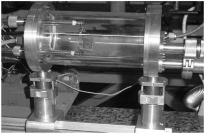
The electrodes of our open MHCD in general are made of approximately 100µmthick molybdenum or cuprum foils separated by a 250 µm spacer of mica with holes varying from 200 to 1000 µm(diameter) through cathode, dielectric, and anode. A closed MHCD in a cathode plane geometry (blind cathode hole for anode hole diameters smaller than 700 µm) was also used in these experiments. Sustaining glow dis-charge voltages were in the range of 200V−400V for Ar. Discharge currentsIdvaried between 0.1mAand 8.0mA. The experiment were performed for an (pD) interval between 0.24 and 56 Torr cm. The operating gas was moderate to high-pressure Ar, between 12 and 800 Torr. For field emission experiment 5µmelectrode spacing was employed in air. The electrode system was placed in a cylindrical quartz chamber with 10cmdiameter and 16cmlength. Before each experi-ment the chamber (Fig. 1) was cleaned, dried and evacuated to about 1mTorr. After that, the chamber was filled with pure argon gas and placed at the desired pressure. Resistors of 47
KΩare used to limit the discharge current.
A digital camera was used to record pictures of the glow discharges. A picoammeter model 414S from Keithley and a digital voltmeter from Minipa were used to measure the cur-rent and voltage in the prebreakdown phase. The dc power supply HP 6920B was employed in the experiments of field emission. SEM images, analysis and top view of cathode hole opening was obtained by a JEOL equipment JSM-5310.
3. RESULTS
0 2 4 6 8 10 12
270 280 290 300 310 320 330
E
D C
B
A
Vd
(V
)
I d (mA)
μ
μ μ
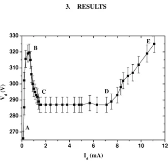
FIG. 2:V−Icharacteristic curve for a hole diameter of 400µmat
40Torr. ForA−B,B−C,C−DandD−Eregions, see text.
In Fig. 2 is shown the evolution of the current with voltage applied to an open MHCD in Ar, operated at 40Torr. As can be seen low current abnormal mode (AB region) is present, which is characterized by a positive differential resistance. A self-pulsed mode (BC region) appearing for currents of 0.6 mAcan be remarked by a voltage drop with current increase, i.e. negative differential resistance. This region is character-ized by high efficiency in producing of ions and metastables species inside the cathode cavity. The confinement of the dis-charge inside the hole can be seen by the optical appearance of the glow. Increasing the discharge current, one can observe a gradually expansion beyond the cavity, covering the cathode surface. The normal glow discharge mode is seen in the CD region where the voltage is held constant as the current in-creases. After point D the discharge shifts to a high-current abnormal glow discharge (DE region), where a positive slope in the current-voltage characteristics is observed. We, gener-ally, avoid the abnormal mode of operation, beyond 10mA due to overheating of the sample. On the other hand, limiting the cathode surface area, the positive slope inI−V curve is always present.
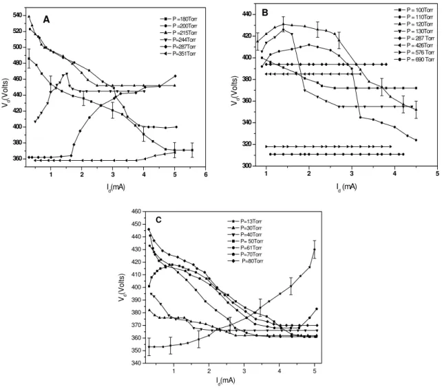
Fig. 3 showsI−V characteristics of an open MHCD (Mo foils) in Ar in the pressure range of 13 – 690 Torr. As pres-sure increases, the sustaining voltage decreases due to more favorable conditions for ionization. They show the typical shape of the abnormal mode, self-pulsed mode and normal mode. The discharge mode characterized by a negative
dif-ferential resistance, region BC, was attributed by Schoenbach et al. [1,3] to the onset of the classical hollow cathode effect, where high ionization efficiency is due to pendulum electrons. Meanwhile, calculations showed that cavity electrons do not have enough energy to do ionizing collisions [4]. Aubertet al. [5] showed that BC region is characterized by self-pulsed mode of operation, where the frequency is driven by the ca-pacitance of the MHCD and by the averaged current deliv-ered by the power supply. Conventional hollow cathode dis-charges are expected to follow Allis-White similarity law [6], V =V(pD), withV being the sustaining voltage for the dis-charge. The lowest value ofpDis given by the condition that the mean free path for ionization must not exceed the hole diameter D. The upper limit for pD is determined by the condition that the distance between opposite cathodes must not exceed the lengths of the two cathode fall regions [7]. High-pressure MHCD operation is expected to be governed by other processes of ionization due to more efficiency in pro-ducing ions, photons and metastable excited atoms, causing secondary electron emission from de cathode [6]. In Fig. 3 we note thatpDvaries between 3 to 7Torr cmfor hollow cath-ode mcath-ode operation, the limits being larger than theoretical 1 Torr cmfor Ar, indicating that others mechanisms than that explained above are influencing the discharge maintenance. In Fig. 3A one can remark that self-pulsed mode appears for pressures ranging from 180 to 244Torr, which correspond to pD values from 4.5Torr cm to 6.4Torr cm. Fig. 3B and 3C show curves having pD values from 3.0Torr cmto 7.0 Torr cm. The total uncertainties (statistical and systematic er-rors) of the measures ofVdwere of approximately 3% for the MHCD of 250µm and 2.5% for 500 and 1000µm. These un-certainties were attributed to discharge voltage instabilities.
A closed MHCD consists of a metal-insulator-metal device with a blind hole in the cathode surface (200µmcathode cav-ity deep). In this configuration a positive slope is observed in I−V characteristics at the entire pressure range, which en-able the operation of discharges in parallel. This means that the discharge itself plays a role of the resistor having the resis-tance corresponding to the slope ofI−Vcharacteristic. Fig. 4
shows theI−V curve for MHCD operated with one and four holes. As can be seen, the positive slope ofI−V curve is present in both cases. In four holes operation the sustaining voltage is reduced for a given current, which is distributed to the array of holes. Here, the plasma serves like a resistor of approximately 15KΩ at a pressure of 30Torr. In this case the plasma was ignited in a four holes plate in Ar, dc opera-tion. Increasing pressure, keeping sustained voltage constant, a higher current is needed to maintain the glow lightening in all holes. It is possible to limit the cathode area covering it with an insulator [8] in order to limit the area available for secondary emission. This way, in open MHCD configuration, a jumping to abnormal mode is observed after gas ignition. Again, a parallel stable operation is possible without ballast-ing the individual discharges.
Brazilian Journal of Physics, vol. 39, no. 1, March, 2009 27
1 2 3 4 5 6
360 380 400 420 440 460 480 500 520 540 A Vd (V ol ts )
Id(mA)
P =180Torr P =200Torr P =215Torr P=244Torr P=287Torr P=351Torr
μ
μ
μ
μ
Ω
1 2 300 320 340 360 380 400 420 4403 4 5
B
Vd
(V
o
lts)
Id (mA)
P = 100Torr P = 110Torr P = 120Torr P = 130Torr P = 287 Torr P = 426Torr P = 576 Torr P = 690 Torr
μ
μ
μ
μ
Ω
1 2 3 4 5
340 350 360 370 380 390 400 410 420 430 440 450 460 C I d(mA) Vd (Volt s) P=13Torr P=30Torr P=40Torr P= 50Torr P=61Torr P=70Torr P=80Torr μ μ μ μ Ω
FIG. 3: I−V characteristic curve for open MHCD operated in Ar with hole diameters of 250µm(A), 500µm(B) and 1000µm(C) as a
function of current and pressure.
To obtain the Paschen’s curves of the MHCD large load resistors were used to limit the current, and hence assum-ing a Townsend mechanism of breakdown. Fig. 5 shows Paschen’s curves for various hole diameters, for MHCD with mica spacerd=300µm, in Ar dc operation. The different size holes of MHCD do not change very much the break-down voltage forpd greater than 0.3Torrcm. Only the left side aspect of pd Paschen’s curves changes whendvaries.
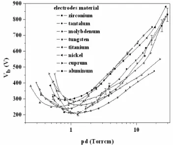
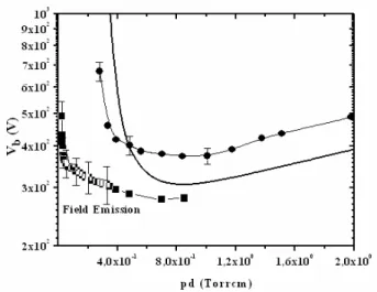
Fig. 6 presents Paschen curves for MHCD constructed with different materials. Aluminum (lower work function) is the material that favors the operation at lower voltages while nickel (higher work function) needs high voltages for break-down. The lower is the cathode material work function the greater is the ionization efficiency. Fig. 7 shows a theoretical Paschen’s curve for plane cathode-anode,d=280µmfor air
(γ=10−3). The Townsend mechanism commands the
break-down process in these discharges and breakbreak-down voltage (Vb) depends onpd, nature of the gas and the electron yield by ion impactγ. In the same figure a Paschen’s curve for a MHCD can be seen. The hole in the center has a diameterD=200 µm. Higher ionization efficiency of the MHCD occurs for low
values ofpd, left-hand branch of the curve, which leads to breakdown voltages lower than plane cathode-anode configu-rations, while for highpdvalues the movement of electrons is attenuated due to high pressure and, in this case, the MHCD becomes gradually comparable to a conventional glow dis-charge, exhibiting the same behavior for breakdown voltages as a function ofpd.
28 M.P. Gomes et al.
0 1 2 3 4 5 6 7
260 280 300 320 340 360 380
Vd
(V)
Id (mA)
1 hole 40 Torr 4 holes 40 Torr 1 hole 30 Torr 4 holes 30 Torr
μ
μ
μ
μ
μ
μ
μ μ μ μ μ
μ
FIG. 4:V−Icharacteristics for closed MHC dc operated in Ar, with hole diameter of 500µmat a pressure of 30 and 40Torr, for 1 and 4
holes. Closed microhollow cathode, Cu anode 100µmthick, operated in Ar. Hole diameterD=500µm. Mica spacer 250µmthick and
cathode cavity deep of 200µm. In the right a digital photography shows an association of MHCDs (D=200µm).
μ
FIG. 5: Paschen’s curves for open MHCD operated in Ar for various hole diameters with Mo foil and mica spacer of 300µmthick.
al. [9] in the breakdown of micro structured electrode arrays in the breakdown curves of Ar, He and Ne and by Torres and Dhariwal [10] in microactuators. In accordance to V-I char-acteristic curve the minimum pressure is about 12Torrfor a MHCD withD=200µm.
One can use the Fowler-Nordheim equation (approxi-mately, because this equation holds only for vacuum [11, 12]) and obtain a microscopic electric field just above the cath-ode surface, responsible for the quantum phenomenon of field emission. In these experiments the total current is given by Id= (λaSF2/Φ)exp(−µbΦ3/2/F), were a and b are
uni-versal constants given by a=1.5414.10−6A eV V−2 and
b=6.8309eV−3/2V nm
−1 [13],λandµare generalized
cor-rection factors,Φis the work function for the relevant point of the emitting surface,F =βE is the microscopic electron field, for a field amplification factorβ. TheI−V curve was
plotted for MHCD in air operated at 20 Torr, Cu cathode with a single 200µmdiameter hole and a very thin electrode spac-ing (5 µm) between electrodes. In Fig. 9 a straight line, with
μ
μ
FIG. 6: Paschen’s curves for MHCD for different cathode materials.μ
Electrodes: 100µmthick; dielectric:d=250µm; hole diameterD= 500µm; gas: Argon.
negative slope, was obtained when ln(Id/Vd2)is plotted versus
V−1
d , a so-called FN plot. For this device configuration, and usingΦ=4.6eV for Cu electrodes, we obtainβ=80 and F=10V/nm, which is a good value for a local microscopic field needed to start the field emission.
4. SUMMARY AND CONCLUSIONS
Brazilian Journal of Physics, vol. 39, no. 1, March, 2009 29
● ■ μ
μFIG. 7: Paschen’s curves for Cu electrodes in air. Plane theoreti-cal cathode-anode (straight line) and microhollow cathode withD= 200m(•,). Full circle electrode spacing of 280µm, full square electrode spacing of 5µm.
μ
FIG. 8: Scanning Electron Microscopy micrographs of cathode sur-face showing roughness and protrusions around hole opening.
not disturb the electric field between the electrodes, which is in this case mainly axial oriented. Increasing the current, the axial electric field begins to be distorted by the space charge accumulated inside the cathode and a strong radial electric field develops [14]. The potential distribution in the gap be-comes strongly non-uniform and the cathode fall is generated. The enhanced electric field at the cathode facilitates ioniza-tion processes and correspondingly a fall in the sustaining voltage and a rise in the current are observed [3].
The breakdown voltage depends on the nature of the gas and pd product. Paschen’s curves are given in Fig. 6 for open MHCD dc operated. All of that have the well-known Paschen curve “U” shape. It can be seen that in the region of the minimum, for Cu and Mo electrodes in Ar gas operation, the breakdown voltage and the(pd)minproduct are in reason-able agreement to the ones found in literature [2]. However, in microhollow cathode operations, as in low pressure hollow cathode operations, the left-hand Paschen’s curves is shifted to a lower breakdown voltage, compared to a parallel-plate glow discharge [14]. Due to micro protusions existing around the hole opening, inducing an enhacement of the local elec-tric field, the breakdown voltage is reduced. This high-local electric field induces the emission of electrons by tunneling
0.00210 0.00215 0.00220 0.00225 0.00230 0.00235 0.00240 -22.2
-22.0 -21.8 -21.6 -21.4 -21.2 -21.0 -20.8
linear fit breakdown
ln
(Id
/V
d
2 )
1/Vd(V-1)
μ
FIG. 9: Fowler-Nordheim plot for 5µmgap device near breakdown.
or field emission process, and for small gaps, be the respon-sible for the breakdown process. In a future work we will in-corporate carbon nanotubes into MHCD hole for enhancing electron emission and reducing breakdown voltages. Spec-troscopic measurements of plasma emission spectral lines are in progress in our laboratory to measure discharge parameters in MHCD at high pressure, such as electron density and gas temperature [15].
Authors would like to thank Jo˜ao Paulo Barros Machado of “Laborat´orio Associado de Sensores e Materiais – INPE”, for technical assistance in Scanning Electron Microscopy and helpful discussions.
[1] K. H. Becker, K. H. Schoenbach and J. G. Eden, J. Phys. D: Appl. Phys.39, R55-R70 (2006).
[2] J. P. Boeuf, L. C. Pitchford and K. H. Schoenbach, Applied Physics Letters86, 071501 (2005).
[3] R. H. Stark and K. H. Schoenbach, Appl. Phys. Lett.74, 25
(1999).
[4] B. N. Sismanoglu and J. Amorim, Eur. Phys. J. Appl. Phys.41, 165 (2008).
[5] X. Aubert, G. Bauville, J.Guillon, B. Lacour, V. Puech and A. Rousseau, Plasma Sources Sci. Technol.16, 23 (2007). [6] D. J. Sturges and H. J. Oskam, J. Appl. Phys.35, 2887 (1964).
[7] K. H. Schoenbach, M. Moselhy, W. Shu and R. Bentley, J. Vac. Sci. Technol. A21 (4), 1260 (2003).
[8] K. H. Schoenbach, A El-Habachi, M. M. Moselhy, W .Shi and R. H. Stark, Physics of Plasmas7, 2186 (2000).
[9] L. Baars-Hibbe, P. Sichler, C. Schrader, C. Gebner, K. H. Ger-icke and S. Buttgenbach, Surf. Coatings Technol.174-175, 519 (2003).
[10] J. M. Torres and R. S. Dhariwal, Nanotechnology 10, 102
(1999).
[11] P. G. Slade and E. D. Taylor, IEEE Trans. Comp. Pack. Techn.
[12] A. J. Wallash, IEEE Trans. Comp. Pack. Techn.40 (3), 1751 (2004).
[13] R. G. Forbes, Solid-State Electronics45, 779 (2001).
[14] R. S Pessoa, B. N. Sismanoglu, J. Amorim, H. S. Maciel and G.
Petraconi, Gas Discharges, Fundamentals and Applications,
ed. J. Amorim, Transworld Research Network, Kerala, India, ch. 7, 175, (2007).