! " ! ! # !# $
!
Environmentally induced cracking of pipeline steels in contact with soil have been investigated. Different soils were prepared in order to determine their physical, chemical and bacteriological characteristics. Slow strain rate testing was carried out by using electrolytes obtained from soil samples and NS4 standard solution. Stress vs. strain curves of API 5L grade X46, X60 and X80 steels were obtained at different electrode potentials (Ecorr, 100 mV below Ecorr and 300 mV below Ecorr) with 9 x 10⁻⁶ s-1 strain rate. The results obtained with API 5L X46 in soil solution were compared with slow strain rate test (SSRT) results obtained using a strain rate of 9 x 10⁻⁷s-1 to the same steel. All results showed the incidence of cracking and their dependence on the potential imposed, revealing the SCC (Stress corrosion cracking) susceptibility of the steels. It was also observed that the hydrogen embrittlement – HE – has an important contribution to cracking initiation and propagation. Cracking morphology was similar to the SCC reported on field condition where transgranular cracking were detected in a pipeline collapsed by land creeping. It was important to point out that even under cathodic potentials the material showed the incidence of secondary cracking and a significant reduction of ductility.
Keywords: buried pipelines, soil, environmentally induced cracking, transgranular cracking
Introduction
1External cracking of pipelines is consequence of complex
interactions between physical and chemical factors (Gomes et al., 2005). Moreover, this cracking can occur during the pipeline service life, if the pipe is under the influence of mechanical stresses. In that case, there are different types of stresses, such as residual stress that is induced by welding procedures and applied stress that is influenced by operational pressure or soil movement. Based on the failure analysis of the pipe cracking, some authors concluded that excessive soil movement was responsible for the coating rupture and the incidence of cracking at a buried pipeline (Souza and Olivier, 2002).
Researchers consider that the cracking process related to external SCC (Stress corrosion cracking) in contact with soil is associated to hydrogen embrittlement (HE). However, basic aspects of this mechanism are not fully understood (Gabeta et al., 2001; Parkins et al., 1994; Zheng, 1996; GRI, 1998; Benmoussa et al., 2006). The main parameter considered by the authors is the pH of the soil. Furthermore, it can process by two types of cracking morphology: transgranular cracking (TGSCC) or intergranular cracking (IGSCC).
Considering the hypothesis that the steel composition and steel mechanical resistance do not affect the cracking morphology, this author concludes that the incidence of TGSCC or IGSCC will be related to the characteristics of the corrosive environment. Then, IGSCC would be associated to relatively concentrated carbonate-bicarbonate solutions with pH values close to 9.5. Consequently, IGSCC is commonly referred as high pH SCC (Parkins et al., 1994). In addition, other authors (Wang and Atrens, 2003) relate that crack propagation for the high pH SCC is mostly intergranular along
ferrite: ferrite (α:α) grain boundaries (GBs). Then, when the crack
tip meets a perlite colony, it may be deflected or it may propagate through the perlite colony in a transgranular manner. The IGSCC propagation of ferrite steels (including pipeline steels) is attributed to a dissolution mechanism.
Paper accepted December, 2008. Technical Editor: Celso K. Morooka
On the other hand, TGSCC occurs in the presence of relatively diluted solutions with pH values of 6.5, called as near neutral pH SCC. Therefore, the classification of SCC is based on the nature of the environment (acidic or alkaline) in contact with external surface of a pipeline.
Another determining factor for IGSCC or TGSCC could be the electrochemical potential, because the potential would determine the reaction mechanism and the products formed in each condition. For instance, it is assumed that TGSCC is associated with the formation of iron carbonate between the coating and the metallic surface. On another point, when IGSCC occurs, only a low amount of iron carbonate is eventually incorporated to a predominant thin film of magnetite. The author also suggests that the mechanism of TGSCC involves hydrogen embrittlement and depends on hydrogen uptake and permeation from the environment (Parkins et al., 1994).
There is an alternative interpretation of IGSCC and TGSCC. According to this author, TGSCC depends on the hydrogen permeation at the crack tip. Cracking nucleation and propagation would be much more influenced by the mechanical loading conditions at the crack tip. Consequently, the influence of the chemical solution would be secondary. The authors describe that the terminology “low pH SCC” used to indicate transgranular external cracking, would be inadequate and could be considered as a misleading indication. After laboratory SCC testing, it pointed out the fact that TGSCC of pipeline steels could be induced in dilute aqueous solutions at different pH values. Therefore, special attention should be done to the mechanical parameters, specially the strain rate at the crack tip (Gabeta et al., 2001).
Nomenclature
Ecorr = Corrosion Potential HE = Hydrogen embrittlement IGSCC = Intergranular cracking NS4 = Synthetic soil solution SCC = Stress corrosion cracking SEM = Scanning electron microscopy SRB = Sulphate reduction bacteria SSRT = Slow strain rate test TGSCC = Transgranular cracking
Experimental
The following steels were carried out, API 5L X46, X60 and X80 (API 5L, 2000). Their chemical composition is presented on Tab. 1. Ferritic matrix with lamellar perlite phases was observed for API 5L X46 and X60 steels, and Martensitic-bainitic structure was observed for API 5L X80 steel.
The experimental tests were developed according to the following steps:
1. Collection of soil samples and field measurements. 2. Physical-chemical analyses of the soil samples. 3. Polarization curves with soil solutions. 4. Slow strain rate testing.
5. Optical and electronic microscopy.
The following solutions were used to carry out electrochemical polarization tests and SSRT:
6. Standard synthetic soil solution, called NS4 solution, used to simulate a synthetic soil purged with a N2 and 5% CO2 mixture for pH adjustment within the range 6.7 and 7.0. The composition is (g/l): KCl: 0.122, NaHCO3: 0.483, CaCl2: 0.093 and MgSO4: 0.131 (Parkins et al., 1994).
7. Soil solutions produced from solid soil samples.
Soil samples were collected at the interface pipeline-soil of a buried pipeline. The solution obtained is similar to the electrolyte formed by the soil with water saturation. In that case, it is assumed that all existing compounds in the soil - like chloride and sulfate - will affect the electrochemical behavior of the soil solution, as well as the pH of this solution that will represent the pH of the groundwater in contact with the pipeline. In fact, Nelf et al. (2005) showed that when the soil contains more chloride or carbonates, some specifics corrosion products are formed, such as alkaganeite, oxychlorides and siderite. In addition, Gupta (1979) related that the maximum corrosivity of soils, in general, has 65% of moisture. In this work, it was used a saturated soil solution with 100% of moisture.
The following in situ measurements were carried out: 8. Soil resistivity
9. Redox potential 10. Electrode potential
Results of physical, chemical and bacteriological analysis of the soils are shown on Tab. 2. The parameters were selected in accordance with the Steinrath proposition (Souza and Olivier, 2002; and Trabanelli et al., 1972), Tab. 3.
Anodic and cathodic polarization curves were obtained with the same solutions previously described. The effect of oxygen was evaluated in aerated and deaerated conditions in soil samples. Therefore, pure nitrogen was used to extract the oxygen.
Slow strain rate tests were carried out with 9 x 10⁻⁶ and 9 x 10⁻⁷
strain rate and with the following experimental conditions: 11. Air – used to simulate an inert environment.
12. Free corrosion potential (Ecor).
13. 100 mV below the corrosion potential. 14. 300 mV below the corrosion potential.
Three electrodes cell was used with platinum as counter electrode and copper sulphate as reference electrode. A potentiostat was used to impose the cathodic potentials. The values of fracture time, elongation and reduction of cross sectional areas were calculated. The analyses of the fracture surface and lateral view were made by optical and scanning electron microscopy (SEM).
Table 1. Chemical composition (wt. %) of the API 5L X46, X60 and X80 steels.
Composition (wt. %) Steel
C Mn Si Cr Ni Mo S P API X46 0.25 1.28 0.34 0.02 0.01 0.03 0.009 0.014 API X60 0.12 1.42 0.29 0.02 0.02 0.01 0.009 0.021 API X80 0.05 1.75 0.17 0.21 0.02 0.17 0.005 0.018
Table 2. Physical-chemical and bacteriological analyses of the soil samples collected.
Collect point Physical-Chemical Parameter
A B C D E
Resistivity (ohms*cm) 320000 57000 54000 45000 10000
Eredox (HNE) 503 466 426 423 366
pH 5.6 5 5.3 5.1 5.6 Humidity (%) 21 30 25 31 23
Cl- (mg/Kg) 55.3 45 37 12.3 45.6 SO4-2 (mg/Kg) 6.2 70 12 6 150.2
S2- (mg/Kg) 18.9 5.8 78 15.9 35.2
SRB (MPN/g) 95 ---- 150 45 1400 Temperature (°C) 25 26 25.5 27 26
Table 3. Corrosiveness indexes of Steinrath and modified Steinrath based on the physical–chemical and bacteriological analyses of the soil samples collected.
Collect points Index
A B C D E
Steinrath -3 -3 -3 -3 -7
Modified Steinrath -5 -3 -5 -5 -9
Results
Five points along the pipeline were selected to collect the soil samples and to perform in situ measurements. Their Steinrath indexes are indicated on Tab. 3. The soil E exhibited the lowest numeric corrosion index. Then, it was chosen for SSRT because of its most corrosivity.
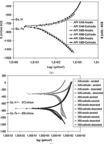
Typical polarization curves obtained for soil and NS4 solutions are presented on Fig. 1. Equilibrium potentials for hydrogen
reduction/oxidation reaction and Fe/Fe2+ are also indicated. Free
(a)
(b)
Figure 1. Anodic and cathodic polarization curves of API 5L X46 steel, (a)
NS4 solutions deaerated with 5% CO2 and N2 gas. (b) Aerated and
deaerated soil solutions, obtained from soil E.
Table 4. Corrosion Potentials of API 5L X46, X60 and X80 steels in NS4 deaerated solution, aerated and deaerated soil solutions.
Ecorr (mV) x SCE
Soil solutions
Steel Conditions
A B C D E
NS4 solution
Aerated -344 -292 -280 -274 -298 ---- API X46
Deaerated -736 -749 -687 -750 -727 -774 Aerated -257 -336 -288 -310 -363 ---- API X60
Deaerated -730 -745 -744 -750 -750 -778 Aerated -253 -325 -299 -288 -334 ---- API X80
Deaerated -732 -750 -752 -738 -756 -774
Anodic dissolution at the corrosion potential was observed in both solutions. The behavior of the materials in soil samples and NS4 solution was similar. It suggests that NS4 solution can be representative of a synthetic soil solution. Electrode potentials measured in deaerated solutions were always below the equilibrium
potential H/H+, based on Pourbaix diagram (Pourbaix, 1963),
corresponding to the system Fe/H2O at 25ºC. Then, it is possible to
conclude that spontaneous hydrogen reduction would occur, from a thermodynamic point of view. The effect of oxygen was more evident in soil solutions. The potential shift for more cathodic values was about 300 mV when the electrochemical cell was purged with pure N2.
Corresponding corrosion potential in deaerated condition, equilibrium potentials for hydrogen reduction/oxidation reaction and the difference between those potentials for each environment are listed on Tab. 5.
Table 5. Corrosion potentials in deaerated condition of NS4 and E Soil solution, H/H+ potentials, and difference between those potentials with potential of H/H+.
Solution Steel API 5L
Corrosion Potential mV
(SCE)
Pot. Equil. H/H+
mV (SCE)
H = Ecor – EH/H+
X46 -704 -67
X60 -708 -71
NS4 solution
X80 -704
-637
-67
X46 -750 -178
X60 -750 -178
Soil solution E
X80 -756
-572
-184
Typical stress vs. strain curves obtained for API 5L X46 steel are shown on Fig. 2, with the following conditions: (a) NS4 solutions with 9 x 10⁻⁶ s-1 strain rate, (b) soil solutions with 9 x 10⁻⁶ s-1 strain rate, and
(c) soil solutions with 9 x 10⁻⁶ s-1 and 9 x 10⁻⁷ s-1 strain rate. The
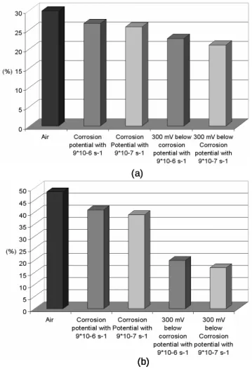
comparison with the curve obtained in air indicates a clear reduction of ductility (average values on Tab. 6). A direct comparison of these parameters is presented on Fig. 3.
The loss of ductility was observed in all tests when lower strain rates were used. The Tab. 7 presents average results of elongation and reduction of area measured after testing. A comparative analysis of these parameters is presented on Fig. 4.
The Fig. 5 shows the lateral surfaces of the SSRT specimens. API 5L X46, X60 and X80 steels were tested in air, immersed in NS4 deaerated solution and in soil deaerated solution, with the
following conditions: (A) air tested, (B) Ecorr - 300 mV in NS4
solution and (C) Ecorr - 300 mV in soil solution. The incidence of
(a)
(b)
(c)
Figure 2. Typical stress – strain curves obtained from SSRT for API 5L X46 steel, (a) NS4 solutions with 9 x 10⁻⁶ s-1 of strain rate, (b) soil solutions with 9 x 10⁻⁶ s-1 of strain rate, and (c) soil solutions with 9 x 10⁻⁶ s-1 and 9 x
10-7 s-1 of strain rate.
(a)
(b)
(c)
Table 6. Average of the results obtained from Slow Strain Rate tests with API 5L X46, X60 and X80 steels in deaerated NS4 solution and deaerated soil solution with 9 x 10⁻⁶ s-1 of strain rate.
API 5L X46 Steel API 5L X60 Steel API 5L X80 Steel
Test
condition ε (%)
Area Reduction
(%)
Time Failure
(h)
ε (%)
Area Reduction
(%)
Time failure
(h)
ε (%)
Area Reduction
(%)
Time failure
(h)
A 29.90 48.50 8.05 21.40 54.00 7.15 18.00 60.00 7.00 NS4 solution NS4 solution NS4 solution B 27.70 43.50 7.45 20.60 47.00 6.90 17.20 53.00 6.75 C 26.70 35.00 7.20 16.90 30.00 5.70 13.30 29.50 5.25 D 25.20 22.50 6.70 14.50 19.50 4.90 12.80 25.50 5.05
Soil solution Soil solution Soil solution B 26.60 41.00 6.71 17.80 40.00 4.92 15.50 47.60 4.45 C 24.80 30.20 6.54 17.30 39.00 4.88 15.10 48.10 4.41 D 22.70 20.00 6.13 14.50 26.05 4.50 14.30 35.00 4.25 (A): Air test
(B): Corrosion Potential (Ecorr)
(C): 100 mV below Ecorr
(D): 300 mV below Ecorr
Table 7. Average of the results obtained from Slow Strain Rate tests with API 5L grade X46 steel in deaerated soil solution, with 9 x 10⁻⁶ and 9 x 10⁻⁷ s-1 of
strain rate.
Elongation
(%) Area Reduction (%)
Test Condition
9*10-6 s-1 9*10-7 s-1 9*10-6 s-1 9*10-7 s-1
Soil test: Ecorr 26.6 25.7 41 36 Soil test:
Ecorr - 300 mV 22.7 21.8 20 15
Figure 8 presents in (a) precipitates of iron carbonate formed at the surface of the specimens of an API 5L X46 steel, tested in deaerated NS4 solution at 300 mV below Ecorr (9 x 10⁻⁷ s-1 strain
rate). The absence of corrosion products was evident. The presence of corrosion products was only detected when the specimens were tested at free corrosion potential. This behavior was reproduced in both solutions, as shown in Fig. 8b.
Optical microscopy of the internal longitudinal cross section of the specimens is shown in the Fig. 9. Therefore, transgranular cracking was detected in all specimens tested in cathodic conditions of corrosion potential minus 300 mV.
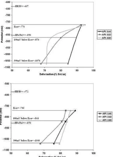
Correlation between electrode potential and the results obtained from SSRT are indicated in Fig. 10. Equilibrium potential for the
reaction Fe/Fe2+ is indicated. It is possible to observe that the
electrode potentials obtained were always below the H/H+
equilibrium potential and above the Fe/Fe2+ equilibrium potential.
Discussion
Five soils samples were collected. But, only the soil considered the most aggressive was used at SSRT (Tabs. 2 and 3). Two methods were used to determine the soil aggressiveness. The first one was through anodic polarization curves (Fig. 1). In that case, all soil samples presented the same electrochemical behavior. Consequently, it was not possible to rank the soils based on the electrochemical characteristics. The second method used was the Steinrath (Trabanelli et al., 1972) and modified Steinrath indexes (Souza and Olivier, 2002), which revealed to be the most accurate method to rank soil corrosiveness. The data presented in Tabs. 2 and 3 show that the most aggressive soil was sample “E”. The low “in
situ” resistivity, low redox potential, the presence of sulphate and sulphate reducing bacteria were the main factors that contributed to the more negative index.
(a)
(b) (a)
(b) (b)
Figure 4. Mechanical parameters of API 5L grade X46 steel tested in SSRT in air, deaerated soil solution at corrosion potential and 300 mV below the corrosion potential, with 9*10-6 s-1 and 9*10-7 s-1 of strain rate. (a) Total
Figure 5. SEM images showing the surface morphology of API 5L X60 steel near to the necking site in the gauge section of tensile sample. (A) Air, (B) NS4 solution with applied potential of 300 mV below the corrosion potential, and (C) Soil solution in the same applied potential with NS4 solution.
Figure 6. API 5L X60 steel – SEM micrograph of fracture surface of SSRT specimen tested in both solutions. (A) Air, (B) NS4 solution with applied potential of 300 mV below the corrosion potential, and (C) Soil solution with the same applied potential; all images: A, B and C with 2000x.
Figure 7. API 5L X80 steel – SEM micrograph of fracture surface of SSRT specimen tested in both solutions. (A) Air, (B) NS4 solution with applied potential of 300 mV below the corrosion potential, and (C) Soil solution with the same applied potential; all images: A, B and C with 2000x.
Figure 8. API 5L grade X46 steel – SSRT, (a) Specimen tested in NS4 solution with 9 x 10⁻⁷ s-1 of strain rate and potential imposed of the 300 mV below the corrosion potential, and (b) Specimen tested in soil solution with strain rate of 9 x 10⁻⁶ s-1 and at the corrosion potential.
Figure 9. Optical microscopy – Longitudinal Section of API 5L X46 steel tested in soil solution, showing the Transgranular crack path followed by a secondary crack.
The first point to be discussed is the open circuit potential (OCP) obtained in soil solutions. According to the E x pH diagram, as proposed by Pourbaix (1963) to explain the thermodynamic
behavior of Fe in H2O at 25 °C, the electrode potentials measured
are within the corrosion area (Tabs. 4 and 5). A difference between aerated and deaerated conditions can be observed. When oxygen is removed from the system the electrode potential changes to a value
below the equilibrium potential H/H+. Consequently, it can be
assumed that in soil solution without oxygen, corrosion is associated to hydrogen reduction.
Another interesting aspect to point out is that the NS4 solution and the soil solution presented similar electrochemical behavior. This fact supports the idea that NS4 solution could be used to represent the corrosive properties of a specific near-neutral soil, at the same pH value. All steels presented a clear decreasing of ductility in both solutions when a more cathodic potential was imposed (Fig. 2). The tests carried out with a potential applied of 300 mV below the corrosion potential in both solutions showed that the total elongation of SSRT test reduced. In addition, presence of secondary cracks, precipitation of cathodic products and loss of ductility were also observed in this condition (Figs. 5, 6 and 7).
Figure 10. Potential versus deformation, (a) NS4 Solution/air and (b) Soil Solution/air.
the E vs. pH equilibrium diagram reveal that the corrosion potentials of all steels in both solutions are positioned in the corrosion domain of iron and below the corresponding equilibrium potential for hydrogen reduction/oxidation (Tab. 5). Therefore, it can be assumed that the materials suffer a combined action of anodic dissolution and hydrogen reduction, which can cause steel embrittlement. Anodic dissolution was evident when the specimens were tested without the imposition of a cathodic potential (Fig. 9).
However, anodic dissolution seems to have a secondary contribution to the deterioration mechanism. Based on the results of SSRT carried out at cathodic potentials, it was evident that the ductility was reduced and the incidence of secondary cracks was more severe despite of the absence of corrosion products (Fig. 8). Suppression of anodic dissolution was possible when the cathodic potentials (100 and 300 mV below corrosion potential) were positioned within the immunity domain of the E vs. pH diagram. Therefore, the secondary cracks and the loss of ductility are attributed to hydrogen embrittlement, since the anodic dissolution was suppressed. This behavior can be confirmed by the Figs. 5 to 7 (B and C), where the presence of cleavage at the fracture surface, secondary cracks and loss of ductility are typical features of brittle fracture. The original fracture mechanism of the materials is shown in Figs. 5 to 7 (A), where the presence of dimples is typical when the specimens are tested in air, suggesting a ductile fracture mechanism.
On the other hand, the increasing number of secondary cracks seems to be in contradiction with the previous explanation. Secondary surface cracking is commonly associated to anodic dissolution. However, this cracking mechanism can be originated by hydrogen uptake and its interaction with the included material.
These results are in accordance with the results reported by Parkins et al. (1994) and TransCanada (1996). They confirm the mechanism of SCC – near neutral pH. This SCC process is characterized by a transgranular cracking morphology (Fig. 9) and a conjoint effect of anodic dissolution and hydrogen embrittlement. All steels presented secondary cracking and loss of ductility when cathodic potentials were imposed in the SSRT test (Fig. 5). However the presence of iron carbonate was not evident in SSRT with strain rate of 9 x 10⁻⁶ s-1.
In relation to the SSRT tests with a lower strain rate (9 x 10⁻⁷ s-1),
it was possible to observe the presence of iron carbonate precipitated at the surface of steels carried out with cathodic conditions in NS4 solution (Fig. 8a). However, when the same test was carried out in soil solution, using the same strain rate, precipitation of iron carbonate did not occur. These results can be explained probably by the presence of
NaHCO3 in the NS4 solution.
Morphology of cracking observed at strain rate of 9 x 10⁻⁷ s-1
was similar to observed at strain rate of 9 10-6 s-1. However, the tests
with strain rate of 9 x 10⁻⁷ s-1 had more severe loss of ductility than
the tests with strain rate of 9 x 10⁻⁶ s-1 (Figs. 2c, 4 and Tab. 7). The
same thermodynamics analyses can be suggested to interpret this phenomenon. This behavior can be attributed to hydrogen diffusion because of the longer time exposure that they were provided. Yan and Weng (2006) have shown that the API X70 steel presented susceptibility to hydrogen absorption.
Results obtained in NS4 solution in comparison to soil solution indicate a more severe loss of ductility in the soil solution (Figs. 2a, 2b, 3 and Tab. 6). Two different aspects can be mentioned to explain this behavior. The first one is related to the soil solutions that were more acid than NS4 solution. The second one is the difference between the cathodic potentials imposed in each solution and the equilibrium potential for hydrogen reduction. It is reasonable to suggest that the driving force for hydrogen reduction is higher in soil
solution (ESCE = -750 mV) than in NS4 solution (ESCE = -704 mV).
Consequently, hydrogen effects would be more intense in soil
solution (Tab. 5 and Fig. 1), as suggested from the analyses of the corrosion potential. The fracture surface of the steel tested in soil sample at the potential of 300 mV below Ecorr, exhibited only cleavage like fracture morphology (Figs. 6c and 7c). However, the same material tested in the same condition in the NS4 solution exhibited a few quantities of dimples, despite of the predominant cleavage like fracture (Figs. 6b and 7b).
A comparison among the materials tested suggests that the API X60 steel presented a more intense deterioration due probably to the higher inclusion content in this steel (Fig. 10). Elboujdaini et al. (2000) obtained similar results testing an API 5L X65 steel in near neutral pH solution. According to this author, crack initiation and propagation will depend on several factors, such as pitting morphology, localized dissolution of inclusions and plastic deformation, despite the fundamental contribution to be caused by electrochemical reactions, like anodic dissolution. The influence of discontinuities acting as stress raisers is pointed out. Smialowska and Lunarska (1981) related that the nonmetallic inclusions present in steels as impurities adversely affect the corrosion resistance of steels. This is true for both general and localized corrosion mechanisms, like pitting corrosion, stress corrosion cracking (SCC), and hydrogen embrittlement (HE).
In this paper, transgranular cracking morphology (Fig. 9) and the adverse influence of cathodic potentials in soil and NS4 solutions are shown. Indication of hydrogen contribution will be confirmed by permeation tests to be carried out using the same steels and environments. The incidence of transgranular cracking was expected since the environments can be considered as near neutral pH solutions, according to the interpretation presented by Parkins. However, the contribution of different stress stages to TGSCC or IGSCC as proposed by Gabeta et al. (2001) deserves further investigation. Additional SSRT is in progress at COPPE/UFRJ as well as constant load tests are scheduled for the next stages of this research.
Conclusion
1 The studied materials exhibited a decreasing ductility as long as more cathodic potentials were imposed. This effect was more evident in soil solutions than in NS4 standard solution.
2 The deterioration mechanism is related to the influence of hydrogen. Transgranular cracking occurred even under cathodic conditions where the anodic dissolution of the steel can be considered as negligible.
3 Cracking morphology was similar to the one presented by Parkins to explain soil induced stress corrosion cracking of carbon steel in near neutral pH conditions.
4 When the specimens were tested using a lower strain rate,
9 x 10⁻⁷ s-1, it was possible to observe the presence of
iron carbonate precipitated at the specimens surface at cathodic conditions in NS4 solution. However, when the same test was carried out with soil solution, using the same strain rate, precipitation of iron carbonate was not identified. These results can probably be explained by the presence of NaHCO3 in NS4 solution.
5 The tests with strain rate of 9 x 10⁻⁷ s-1 had more severe loss
of ductility than the tests with strain rate of 9 x 10⁻⁶ s-1. This
behavior can be attributed to hydrogen diffusion because of the longer exposure times that they were provided.
Acknowledgement
References
API Specification 5L, 2000, “Specification for line pipe”, API code, 42nd
Edition.
Benmoussa, A., Hadjel, M. and Traisnel, M., 2006, “Corrosion behavior of API 5L X-60 pipeline steel exposed to near-neutral pH soil simulating solution”, Materials and Corrosion, Vol. 57, pp. 771-777.
Elboujdaini, M., et al., 2000, “Initiation of stress corrosion cracking on X-65 pipeline steels in near-neutral pH environment”, Proceedings of the 3rd
International Pipeline Conference, ASME, Calgary, Canada, Vol. 2. Gabeta, G., et al., 2001, “Strain rate induced stress corrosion cracking in buried pipelines”, British Corrosion Journal, Vol. 36, no. 1.
Gomes, J.A.C.P., Bastos, I.N., Costa-Matos, H.S. and Vasconcellos, J.F.V., 2005, “A continuum damage model for the stress corrosion cracking of austenitic stainless steel”, Journal of the Brazilian Society of Mechanical Sciences and Engineering, Vol. 27, pp. 186-191, 2005.
GRI Research, 1998, “Stress corrosion cracking mechanisms in pipeline”, Pipeline & Gas Journal.
Gupta, S. K. and Gupta, B. K., 1979, “The critical soil moisture content in the underground corrosion of mild steel”, Corrosion Science, Vol. 19, pp. 171-178.
National Energy Board, 1996, report of the inquiry, “Stress corrosion cracking on Canadian oil gas pipelines”, Calgary, Canada.
Nelf, D., Dillmann, P., Bellot-Gurlet, L. and Beranger, G., 2005, “Corrosion of iron archaeological artefacts in soil: characterization of the corrosion system”, Corrosion Science, Vol. 47, pp. 515-535.
Parkins, R.N., Blanchard, W.K. and Delanty, B.S., 1994, “Transgranular stress corrosion cracking of high-pressure pipelines in contact with solutions of near neutral pH”, Corrosion, Vol. 50, no. 5, pp. 394-408.
Pourbaix, M., 1963, “Atlas d’équilibres électrochimiques à 25°C”,
Publication du Centre Belge D’Étude de la Corrosion (CEBELCOR), Paris. Smialowska, Z.S., Lunarska, E., 1981, “The effect of sulfide inclusions on the susceptibility of steels to pitting, stress corrosion cracking and hydrogen embrittlement”, Materials and Corrosion, Vol. 32, pp.478-485.
Souza, B.G. and Olivier, J.H.L., 2002, “Circumferential SCC in pipeline due to land creeping”, Proceedings of the 4th International Pipeline
Conference, ASME, Calgary, Canada, pp.1-9.
Trabanelli, G., Zucchi, F., Arpaia, M., 1972, “Methods of determination of soil corrosiveness with respect to metallic structures”, Proceedings of the
Chinica Pura ed Applicata, Vol. III, Sezione V, n. 4, pp. 43-59.
Wang, J.Q. and Atrens, A., 2003, “SCC initiation for X65 pipeline steel in the ‘high’ pH carbonate/bicarbonate solution”, Corrosion Science, Vol. 45, pp. 2199-2217.
Yan, M. and Weng, Y., 2006, “Study on hydrogen absorption of pipeline steel under cathodic charging”, Corrosion Science, Vol. 48, pp. 432-444.
Zheng, W., 1996, “Pipeline SCC in near neutral pH environment: recent progress”, Proceedings of the 1st International Pipeline Conference, ASME,