Sample Preparation Method for
Sanning Fore Mirosopy
I.R. Jankov 1
,R.N. Szente 2
,I.D. Goldman 1
, M.N.P. Carre~no 3
,
J.W. Swart 4
, and R. Landers 5
1
InstitutodeFsia,Universidadede S~aoPaulo,S~aoPaulo,SP, Brazil
2
MehanialandEletrialDivision,IPT,CidadeUniversitaria,
CEP01064-970,S~aoPaulo,SP,Brazil
3
Laboratorio deMiroEletr^onia, EsolaPolitenia,
Universidadede S~aoPaulo,S~aoPaulo,SP,Brazil
4
CCS,UniversidadedeCampinas, Campinas,SP,Brazil
5
InstitutodeFsia,UNICAMP,Campinas,SP, Brazil
Reeivedon21May,2001
We present a method of sample preparation for studies of ion implantation on metal surfaes.
Themethod,employingamehanialmask,isspeiallyadaptedforsamplesanalysedbySanning
Fore Mirosopy. Itwassuessfully testedonpolyrystallyne oppersubstratesimplantedwith
phosphorusionsatanaelerationvoltageof39keV.Thehangesoftheeletrial propertiesofthe
surfaeweremeasuredbyKelvinProbeForeMirosopyandthesurfaeompositionwasanalysed
byAugerEletronSpetrosopy.
I Introdution
Changesinduedonasurfaeduetoaertain
pro-essanbe,inpriniple,detetedbytwodierenttypes
ofmeasurements: a)thedeterminationoftheabsolute
valueofthesampleharateristisbeforeandafterthe
proessthatinduedthehanges;b)theuseofadiret
omparison, i.e., relative measurements, between the
sample(orpartofif)thatdidnotundergoanyproess
andthesample(orpartofit)that wasexposedtothe
hangingproess.
The rst type of measurement usually requires a
standardreferenesamplewithharateristis(theones
ofinterest)thatarewelldenedanddonothangewith
time. However,apossibleproblem withthis approah
isthateventheharateristisofthestandardreferene
samples are notalwaysonstantand might vary with
someunknownexperimentalparameter(forhangesof
some properties of gold; see for example [1℄). This is
partiularly the asefor measurementsnot performed
underUHVonditions[2,3℄. Evenmeasurementsunder
UHV onditionsmightnotprovideabsolutevalues
un-lessthestandardreferenesampleispreparedinsitu.
Themajoradvantageoftheseondtypeof
measure-mentsisthatthereisnoneedfortheseparatestandard
referene sample, sine thereferene value anbe
ob-to envision a method where partof thesample is
ex-posedto themodifyingproesswhiletheotherpartof
thesample iskeptat thesameinitial onditions, thus
avoidingtheneedofaseparatestandardreferene.
Inthis paper, we use the seond approah to
pro-poseasamplepreparationproedureforsanningfore
mirosopy(SFM) studies. Theproedure reates, on
thesamesample, twotypesofregions, i.e., oneregion
that is exposed to the modifying proess and another
regionthat isnotmodied. Intheasepresentedhere
themodifyingproesswasionimplantation, whih
in-dued varioushangesonthematerial, inludingwork
funtion hanges, determinedbyaKelvinProbeFore
Mirosopy[4-6℄.
Thevalidityoftheproposedmethodisbasedontwo
assumptions:
a)during themodifyingproessthe harateristis
of parts ofthe samplesnot exposed to theproess
re-main onstant;
b)afterthehangeswereinduedinertainregions
of thesample, the harateristis of everyregion
II Experimental proedures
II.1. General desription
In order to prepare a samplefor KPFM using the
seond methodology presented above, a mehanial
mask with ne denition, positioned above the
sub-strate,wasusedasdesribedbelow.
Theexperimentalproeduresinvolvedthehoieof
materials to be studied, the method of ion
implanta-tion tobeused, thedesignand onstrutionof a
suit-able tool in order to have, in the same sample, areas
exposedand notexposedto the ionimplantation
pro-ess (aording to the method proposed above), and
surfae analysis of the produed sample. Speially,
thedevelopedexperimentalproeduresonsistedofthe
following steps: a) Sample preparationb) Prodution
of amehanialmask;) Ion implantationproess; d)
Surfae analysis. A moredetailed desriptionofthese
stepsisgivenbelow.
II.2. Sample preparation
The method developed for preparingsamples that
arepartiallyexposedtoamodifyingproesswasarried
outonpolyrystallineopper.
First, the substrates were mehanially abraded
with sand paper up to 2400 mesh. After leaning in
ethanol, the polishing proess was ontinued with
di-amond pastes (produed byKG Sorensen) of6 m,3
mand1mingrainsizerespetively. Thesubstrates
were leaned in ethanol and distilled water after eah
step. Afterthepolishingproess,thesampleswere
ex-aminedusinganatomiforemirosopefor
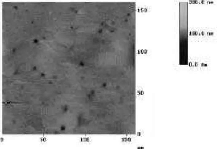
determin-ing thesubstrate topography. In thesemeasurements,
themaximumtopographydierenewasoftheorderof
250nm asitanbeseenin Fig.1.
Figure1. Topographyofoppersubstratemeasuredwith
II.3. Mehanial mask
Aspeialmehanialmaskwasdesignedand
manu-faturedtobeusedduringtheionimplantationproess.
Themainobjetiveforusingamehanialmaskon
thetopof the sampleundergoingan ionimplantation
proessistoreate,onthesamplesurfae,adetermined
patternofimplantedandnon-implantedregions. This
allowsthedeterminationofhangesinduedbythe
pro-essonthesamesampleasexplainedabove(although
somesurfaeanalyseswerearriedoutfordierent
sam-ples exposed to the same proess). The main points
whih were onsidered in the design of the mask are
presentedbelow,andfollowedbythedesriptionofthe
produtionstepsusedinmanufaturingofthe
mehan-ialmask.
II.3.1 Designof themehanialmask
Thedesignofthemehanialmaskhadtotakeinto
onsiderationthefollowinglimitationsand
harateris-tis:
1. The piezoeletri devie of a SFM
equipment limits the maximum sanned
area to around 100100m for a typial
onguration. Ifonewantstobesurethat,
within this sanned area, there is at least
oneborderregion(betweentheregionswith
and withoutimplantedions) themask has
to reateregionssmallerthan afewtenths
ofamiron.
2. Sine SFM measurements annot
provide surfae omposition, the
mehan-ial mask should allow the prodution of
twosamplessimultaneouslyunderthesame
onditions. This would provide one
sam-ple to be used in the SFM measurements
and another one (presumably idential to
therst sample) to be used in the
ompo-sitiondetermination. Thisproedureisdue
to the fat that mostof the surfae
analy-sesaredestrutive;ifonesampleisusedfor
bothtypesofanalyses,therewillbealways
unertainty if some sample harateristis
were hanged during the ion implantation
proessorduring thepreviousanalysis.
3. Depending on the dose of ions
im-planted on the sample, it ould be
impos-sible to dierentiate an implanted from a
sample by the proess due to the
impos-sibility of determining the border between
the implanted and the non- implanted
re-gions. Therefore, the mask should reate
thelargestpossiblenumberofborders(this
meansthelargestpossiblenumberof
sepa-rateimplantedregions).
4. Thedimensionsofthemaskwerealso
limited by the equipment used in its
pro-dution and by the equipment used in the
proessof ionimplantation.
A speial version of the programme AutoCAD 10
was used for thedesign of themehanialmask. The
designofthemehanialmaskusedinthisworkanbe
seenin Fig.2.
Figure2. Themehanialmasklay-out(frontpart).
The used ion implantation equipment limited the
mask size to 25 25 mm. The mask anbe used for
theprodution of twopairs ofsamples simultaneously
(in ase just onepair is needed, half of the mask an
beoveredduringtheionimplantation). Twodierent
typesoffeaturesanbeseenonFig.2.: a\nine-island"
sreenanda\three-island"sreen. Thesampleforthe
SFM measurementsis plaed under the \nine-island"
sreenandthesampleforsurfaeompositionanalysis
under the\three-island"sreen. Eightoutofthe nine
regionsonthe\nine-island"sreenand twooutofthe
threeregionsonthe\three-island"sreenontain
hun-dredsofretangularareaswithsizeof100 40m(those
The sreen is approximately 4.5 m thik and
shouldbeabletostopompletelyphosphorusionswith
upto24MeVaelerationvoltage(thefatwhetheran
ion beamwith ertainenergyanbestopped depends
on thesreen thikness). The ionbeamwill just pass
throughtheretangularareas,thushangingthe
prop-ertiesof thesamplein theretangular-shapedregions.
Thereasonforhavingeightseparateregionswith
ret-angular struture on the \nine-island" sreen instead
of onebigregion, is that thesreen materialis fragile
and an rak due to the surfaetension. The
spa-ing between the retangular areas is 50 m, whih is
suÆientfordistinguishingbetweentheimplantedand
non-implantedregions(implantedones should be
nar-rower).
The regions without the retangular struture on
the \nine-island"sreen and the\three-island"sreen
areatuallylargeholesinthesreen(withsizesof22
mmand8:55:5mmrespetively)whereanionbeam
an passandhit thesamplesurfaeuniformly. Onthe
\nine-island"sreen, the regionwithoutthe
retangu-lar struture was designed to failitate the searh for
the areas of interest on the sample after the ion
im-plantationproess(inasetheimplantedareasarenot
visible,thesamplesurfaeanbemarkedthroughthis
hole). The region without the retangular struture
on the\three-island"sreen was designedin order to
be used for surfae omposition analysis (the area is
suÆiently large for most of the surfae omposition
analysis tehniques). The two regions with the
ret-angular struture on the \three-island"sreen an be
used for omparison between the SFM results on the
sample used just for this type of measurements (i.e.
the one under the \nine-island" sreen)and the
sam-pleusedforsurfaeompositionanalysis(i.e. underthe
\three-island"sreen). Inthisway,theinuenedueto
thesurfaeompositionanalysisontheresultsofSFM
measurementsanalsobestudied.
II.3.2. Prodution ofthe mehanialmask
The mask, was designed and manufatured in the
MiroEletroni Laboratory of the Polytehni
Engi-neering Shool of the University of S~ao Paulo. The
produtionof themaskanbedividedintotwomajor
stages:
1. Produtionofhromepatternmasks
Sineitisnotpossibletotransferthe
de-siredomputerdesign diretly into the
sil-ion mehanial mask used in the ion
im-plantation proess, an intermediate mask
originally designed in the omputer. One
produed, the intermediate masks an be
used for the prodution of an indenite
numberofsilionmehanialmasks.
2. Prodution of silion mehanial
masks
Themehanialmaskonsists ofa
sub-strate, made of silion, and of a sreen,
made of silion, oxygen and nitrogen,
re-atedon thesilionsubstrate. The
geomet-rial patternfrom ahromemaskis
trans-ferredtothesreenmaterialofthe
mehan-ialmask. Thesilionsubstrateatsonlyas
asupportfortheomplexoxidesreen. The
sreen isformed ononeof the sides ofthe
silionsubstrate andthe omplexoxideon
theothersideofthesubstrateisremoved
al-mostompletelytopreventundesired
stop-ping of ions (the substrate is not removed
ompletely in order to protet the silion
substrateduringthesilionorrosionstage;
seestage8ofthemehanialmask
produ-tionin theAppendix). Therefore, two
dif-ferenthrome pattern masks (one for eah
sideofthesilionsubstrate)areneeded(see
Fig.3.).
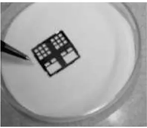
Figure4. Mehanialmask.
Eahofthetwomajorprodutionstagesonsistsof
severalsub-stages. Thestepsneededfortheprodution
of the hrome pattern and the silion mask are given
in detailin theAppendix. Themehanialmask used
in the experiments an be seen in Fig. 4. The small
divisionsinsideeahsquareannotbeidentiedinthis
magniation.
II.4. Ion Implantation
Two polished opper substrates were implanted
with phosphorus ions (with a dose of 8:45 10 15
ions/m 2
)atanaelerationvoltageof39keV.Theion
implantation was performed with an Eaton GA 4204
implanteroftheCentreofSemiondutorComponents
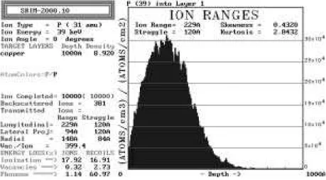
of theUniversity of Campinas. In order to determine
therangesofthephosphorusionswiththeaeleration
of 39 keV, TRIM simulations were performed (SRIM
version2000.10[7℄). Inthose simulations, 10.000ions
wereusedandthemaximumionrangewasaround600
A
(seeFig.5.), thusonrmingthat themehanialmask
produed here (with a 4.5 m thik oxide layer
om-pletely stopping the inident ions) ould be used for
theexperiments.
II.5. Surfae Analysis
One of the two implanted samples was used for
AugerEletronSpetrosopy(AES)in order to
deter-minethesurfaeomposition. For determiningthe
in-ueneof the ion implantation proess on thesurfae
omposition of samples, one substrate whih did not
undergotheionimplantationproesswasalsousedfor
AES.TheAESanalyseswereperformedin theSurfae
PhysisLaboratoryoftheInstituteofPhysis,
Univer-sityofCampinas.
The other implanted sample was used for Kelvin
or-is diretly related tothe work funtion ofthe surfae.
The VoltaPotentialbetween the tip (madeof Pt and
Ir) and a freshly leaned polyrystalline opper
sub-stratewasusedasareferenevalue. Itshouldbe
men-tionedthattheonlusionsdrawnfromthese
measure-ments are not dependent on whih referene material
wasused. Simultaneously to the Volta Potantial,
to-pographymeasurementsoftheoppersamplewere
per-formed with KPFM equipment. The KPFM analyses
wereperformed in theLaboratoryof Material Siene
andEngineeringoftheOhioStateUniversity.
Figure5. SRIMresultsforphosphorusionswithenergyof39keV.
III Results and Disussion
Oneofthemostimportantpartsofthepreparation
proedurefortheSFMsampleisthetreatmentreeived
by thesubstrate. Sine hanges onthe topographyof
thesampleaninuenetheSFMmeasurements,great
areshouldbetakeninordertoprodueuniformly
pla-narsubstratesurfaes. Althoughthepreparationofthe
opper substrates that were used for the experiments
desribedhereyieldedgoodresults,theproedure an
befurther improved. Reently, Wadsak et al. [8℄
ar-riedoutaomparisonofdierentpreparationmethods
of oppersubstrates forsanning fore mirosopy
in-vestigations.
Thesurfaeoftheimplantedoppersubstrateswere
investigatedwithanoptialmirosope. The
retangu-larareasinFig. 6. areregionswhihreeived
phospho-rusionsduringtheionimplantation. The
retangular-shaped struture mathes the geometrial pattern of
themehanialmask. Somesarsontheoppersurfae
wereobserved,whihareprobablyduetothehandling
ofboththemehanialmaskandtheoppersubstrates
duringtheionimplantationproess.
The results of AES analyses for the opper
sub-strates(before ion implantation) are shown in Fig.7a.
The presene of some ontaminants wasobserved. In
order to determine the thikness of the ontaminant
layer,athiklayerofabout50
Aofthesubstrate
sur-fae wasremoved by Ar sputtering. The omposition
analysis of the opper substrate after the sputtering
proessisshowninFig.7b.
ItanbeseenfromtheseguresthatonlyOandC
are present on theopper surfaeafter the sputtering
proess. It anbe onluded that the other
ontami-nantsobservedontheoppersurfaewithout
sputter-ing(S,ClandN)werejustpartofaontaminantlayer
of lessthiknessthan50
A.Thefat that OandCare
stillfoundevenaftertheremovalofapproximately50
A
of thesurfaeisexpeted sineopper,in air,forms a
relativelythikoxidelayerveryquikly[9,10℄. Carbon
Theresultsobtainedfrom theAESanalysisforthe
implanted opper sample are shown in Fig. 8. The
ontaminants found on the opper substrate without
ion implantation(Fig. 7.) analso beseenonthe
im-planted sample. One new peak, around 120 eV, was
found. Thispeakindiates thepreseneof phosphorus
onthesamplesurfae. Itshouldbenotedthat no
on-taminantsdueto theuseof themehanialmaskwere
found.
Figure7a. Coppersubstratebeforesputtering.
Figure7b. CoppersubstrateaftersputteringFigure7.
ResultsofAESforoppersubstrate.
Figure8. ResultsofAESforimplantedoppersample.
Sometopographyresults andVolta Potential
mea-surementsforaertainregionoftheimplantedsample
areshowninFig. 9(whereweanseenthe
retangular-shaped patternof the implantedareas.) Thereare no
notieablehangesonthetopographyoftheimplanted
regions.
Eightdierentareaswitharetangular-shaped
pat-ternonthesamesamplewereexaminedfortopography
andVolta Potential. Theresults forthe Volta
Poten-tial are shown in Table 1. The results for both the
implanted and non implanted regions are given with
respet to the referene oppersubstrate used for the
measurements. Sinethesameopperrefereneisused
for the measurements of the implanted and non
im-plantedareas,there isnoinuene ontheobtained
re-sults.
TheVoltaPotentialdiereneindiatesthehange
oftheopperworkfuntion duetothephosphorusion
bombardment. In this ase, an inrease of 25mV in
averagewasobservedifweomparetheionimplanted
region with the non implanted region. Although the
valuesfortheVoltaPotentialdierenehangeslightly
from area to area, the work funtion of the opper
learly shows an inrease for the implanted areas as
omparedwiththeoriginaloppersurfae.
Itisnotyetlearwhethertheworkfuntionhanges
were indued by the presene of phosphorus on the
surfaeorby the ion implantation proess (for
exam-ple, heating of the sample, hange of the topography
by sputtering, et.) [11,12℄. Further experiments are
needed in order to determine what is the mehanism
for the work funtion inrease. Nevertheless, the
re-sultsoftheexperimentsobtainedin thisworkindiate
that the method for reating implanted and non
im-planted regions in a sample is satisfatory for KPFM
Area Non-implanted ImplantedRegions VoltaPotential
Regions Dierene
1 0.110V 0.122V 12mV
2 0.150V 0.172V 22mV
3 0.150V 0.170V 20mV
4 0.110V 0.166V 56mV
5 0.150V 0.170V 20mV
6 0.120V 0.150V 30mV
7 0.115V 0.140V 25mV
8 0.155V 0.170V 15mV
Table1. KPFMresultsfordierentareasofanimplantedoppersample.
Figure9. ResultsofKPFMforimplantedoppersample.
Itshouldbenotedthatthemethodommonlyused
in the eletroni industry for produing dierent
pat-terns ona surfae, i.e., themethod employinga
pho-toresistordiretlyonthesubstrate(whihwouldatas
the mehanial mask desribed above), ould be used
onlyforoneexperiment,sinethephotoresistor would
beattahed tothesamplebeingprepared. This isone
oftheadvantagesoftheuseofthemehanialmaskto
preparesamplesforKPFM.
IV Conlusions
In this paper, we desribe a methodology for
prepar-ing samples to be used by a KPFM equipment. The
method wasused tostudytheinueneofion
implan-tationofphosphorusontheworkfuntion ofopper.
Changesoftheworkfuntiononoppersurfaewere
notied due to the implantation of phosphorus ions.
However,thedeterminationoftheexatmehanismfor
Aknowledgements
Oneof theauthors (I.R.J.) would liketo
aknowl-edgethenanialsupportreeivedfrom FAPESP.
Referenes
[1℄ W.N.Hansen,K.B.Johnson,Surf.Si.316,373(1994).
[2℄ M. Saint Jean, S. Hudlet, C. Guthmannm, J. Berger,
Phys.Rev.B56,15391(1997).
[3℄ M. Nonnenmaher, M.P. O'Boyle, H.K.
Wikramas-inghe,Ultramirosopy42-44,268(1992).
[4℄ Y. Martin, C.C. Williams, H.K. Wikramasinghe, J.
Appl.Phys.61,4723(1987).
[5℄ J.M.R.Weaver,D.W.Abraham,J.Va.Si.Tehnol.B
9,1559(1991).
[6℄ M. Nonnenmaher, M.P. O'Boyle, H.K.
Wikramas-inghe,Appl.Phys.Lett.58,2921(1991).
[7℄ J.F. Ziegler, J.P.Biersak, U. Littmark, The Stopping
[8℄ M.Wadsak,M.Shreiner,T.Aastrup,C.Leygraf,Appl.
Surf.Si.157,39(2000).
[9℄ J.C. Yang, B.Kolasa, J.M. Gibson, M. Yeadon, Appl.
Phys.Lett.73,2841(1998).
[10℄ K.I.Tanaka,T.Fujita,Y.Okawa,SurfSi.401,L407
(1998).
[11℄ P.J.Ratlie,R.A.Collins,Phys.Stat.Sol.A 78,547
(1983).
[12℄ B.J. Love, P.F. Pakman, J. Mater. Si. 33, 1359
(1998).
Appendix
1)Preparationofthehromemask. Athin hrome
layer(300nm)wasdepositedbyasputteringdeposition
tehnique,usingaMagnetronBalzersBAS450
Sputter-ingSystem,onglassplates(Croningglass)whihwere
rinsedinthreedierentsolutionspriortothedeposition
proess:
15-20 minutes in TriChloroEthylene (TCE) on
80 Æ
C;
15-20minutesinaetoneon80 Æ
C;
15-20minutesinisopropanolon80 Æ
C.
2)Cleaningofthehromemaskswasperformedby
plaing the prepared hrome wafers in a solution of
H 2 SO 4 and H 2 O 2
(proportion 3:1) at a temperature
of 105 Æ
Cduring 15 minutes; andthen byleaning the
maskswithdeionizedwaterfor10minutes. Afterwards,
thehromemaskswereimmersedinalohol(40 Æ
C)for
20minutesand driedwithajetofN
2 .
3) The photoresistor used in the reported
exper-iments was a positive photoresistor AZ1518 diluted
in AZ1500 Thinner (proportion 16:9) produed by
Hoehst. Theappliationtehniqueinvolvestwostages:
statiappliationofaphotoresistorsolutiononthe
sur-fae of hrome wafer and subsequent aeleration in
thespinnerfor30seondswithonstantrotationspeed
of 4000rpm. This proess generates auniform lmof
thephotoresistorwith about0.7mofthikness. The
hromemasks witha photoresistorwere submittedto
softbakingfor20minutesatatemperatureof 80 Æ
C.
4)Thephotoresistorlmwasthenexposedtolight
using a Miropattern printer, Imagen 100, Researh
Devies Instruments, at the UV-lose spetrum
(350-500nm). The omputer oupled to this equipment
transfersthedesignedgeometry patternto thesystem
memory. This image is reprodued onthe
photoresis-torlmbyexposingthelmthroughthemovableslits
(whihletlightpassonthedesiredregionsonly). The
whole proedure takesapproximately3hoursfor eah
hromewafer.
5) The parts of the photoresistor lm whih were
exposed to light were removedusing a351Developer,
made by Hoehst, diluted in water (proportion 5:1).
temperature treatment (90-100 Æ
C) during 30 minutes
(hardbaking).
6) Thehromemaskswith theremaining
photore-sistorlmwereplaedduring3minutesinasolutionof
160gof eriumammonium nitrate and45ml ofglaial
aetiaid. Thissolutiondissolvesunprotetedhrome
only, leavingintatthephotoresistorlmandthe
pro-tetedhromebelowthelm.
Inordertoremovetheremainingphotoresistorlm,
thehromemaskswererstimmersedfor5-20minutes
inaetone(40 Æ
C)andtheninTCE(5-10minutes). The
masksarethenwashedwithajetofaetone,waterand
isopropanol.
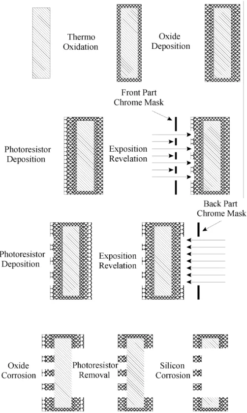
The prodution of the silion mehanial mask is
dividedinto sub-stages (the shemati diagram of the
produtionanbeseeninFig.10.):
1) Before the use, the silion substrates were ut
(2525mm)andleaned,followingthestepsmentioned
below: 15 minutes in asolution of H
2 SO 4 and H 2 O 2
(proportion 3:1) at a temperature of 105 Æ
C; 10
min-utesintapwater;5minutesindeionizedwaterltered
with Millipore Milli-Q Plus (water with resistivity of
18.2Mm);15minutesinasolutionofH
2 O,NH 4 OH and H 2 O 2
(proportion 5:1:1) at temperatures up to
75 Æ
C; 10minutes intapwater;5minutesin deionized
water ltered with Millipore Milli-Q Plus; 15 seonds
inasolutionofNH
4
F(40%)andHF(49%)(proportion
25:4)BOEEthant;15 minutes in tapwater; 15
min-utesin asolution of H
2 O, H
2 O
2
and HCl (proportion
6:1:1)atatemperatureof80 Æ
C;10minutesindeionized
waterlteredwithMilliporeMilli-QPlus;
Thesubstratewasnally driedwithanitrogenjet.
As mentioned, the reation of the oxide layer on
thesilionsubstrateisveryimportantintheproessof
fabriation of the mehanialmask, sine the pattern
ofthehromemaskistransferredtothislayerandnot
tothesilionsubstrate.
Theoxidelayerisreatedintwosteps. First,it
o-ursathermo-oxidationandthenadepositionofa
om-plexoxidelayer (Si, O and N). The thermo-oxidation
wasobtainedbyplaingthesubstratesinanoven
ham-ber at 1100 Æ
C, lled suessively with various gases
(rst5minuteswith O
2
, followed by25 minutes with
H
2
Ovapourandnally40minuteswithN
2
). This
pro-essreatesalayerofathermo-oxideofapproximately
0.5m.
Thedepositionoftheomplexoxidewasperformed
usingaPECVD2system(PlasmaEnhanedChemial
VapourDeposition)usinganeletridishargethrough
amixture of high purity SiH
4
(99.89%) and high
pu-rity N
2
O(99.999%). Theowrates ofthe gaseswere
37.5smfor N
2
Oand 15sm forSiH
4
. That proess
reatesaomplex oxidelm of SiO
x N
y
(the
omposi-tionanalysis ofthis lm determinedvaluesof 1.57for
xand0.34fory). Contrarytothermo-oxidation,where
eahsideofthesubstratehastoundergothedeposition
separately. Theappearaneofanapproximately4m
thiklmtakesabout3hours.
Afterwards, the substrates were rinsed in dierent
solutions: 15-20 minutesin TCEat 80 Æ
C;15-20
min-utesinAetoneat80 Æ
C;15-20minutesinIsopropanol
at80 Æ
C.
Thethermo-oxidehasatwo-fold role. It promotes
theadhesionofthedepositedoxidelmanditgives
ex-traprotetiontothesilionsubstrateduringthesilion
orrosionproess(stage8of themehanialmask
pro-dution). Thethikness ofthe lmshould betailored
aordingtotheionspeiesandtheenergyofthebeam
usedintheionimplantationexperiments.
Inorder to promotethedehydrationof thesurfae
a primer was overedon the substrate surfae before
theappliationofthephotoresistor(the samesolution
asin the hrome mask prodution). The thikness of
thereatedphotoresistor lmwas about2.2 m. The
silion substrateswith a photoresistorlayerwere
sub-mittedtoasoftbakingfor20minutesatatemperature
of80 Æ
C.
AKarl Suss MJB3Mask Alignerwasused forthe
lightexposingproess(lightof350-500nmwavelength).
This step lasted 100 seonds for eah side of the
sil-ionsubstrate. That equipmentuses the hrome
pat-ternmasksinordertoreatethedesiredpatternonthe
photoresistorlmofthesilionsubstrate,i.e.,lightan
passthroughonlyifthereisnohromeonthepattern
mask.
Afterthelightexposingproess,thesubstrateswere
submittedtotheproessofdevelopingandhardbaking,
desribedin stage5of thehromemaskprodution.
Beforethepartialremovalof theoxide(just in the
areas where the photoresistor lm was destroyed) on
one side of the substrate, the other side of the
sub-strate was proteted with Apiezon r
. The substrates
wereplaedinasolutionofNH4F(40%)andHF(49%)
(proportion25:4),BOE r
Ethant,for7minutes,whih
removesompletelytheoxideatthedesiredareas.
After the partial removal of the oxide layer, the
Apiezon r
wasremovedwithTCE.Thestrippingofthe
photoresistor and the leaning of the substrate were
performedasdesribed in stage 7of thehromemask
prodution.
Thestages 3-7 were repeated for the other side of
thesilionsubstrate.
Aftertheoxidelayerwaspartiallyremovedonboth
sidesofthesubstrate,aorrosionproessofthesilion
substratewasthenperformed. Onlythesilionloated
belowtheoxideareasremovedintheproess(desribed
instage6above)isdissolved. Thesubstratewasplaed
for7hours,at atemperatureof80 Æ
C,inasolutionof:
108mldeionizedwater;51mlisopropanol;50gKOH.
Aftertheorrosionstep,thesubstrateswereleft10
minutesinastreamofdeionizedwaterandleanedwith