Effect of power parameter and
induction coil on magnetic ield in
cold crucible during continuous
melting and directional solidiication
Male, born in 1975, Ph.D, Associate Prof., Vice Director of Department of Materials Processing Engineering. Main research interests: cold crucible directional solidiication, high temperature alloys and multi-crystalline silicon.
E-mail: [email protected]
Received: 2011-10-11; Accepted: 2011-12-23 *Chen Ruirun
*Chen Ruirun, Yang Jieren, Ding Hongsheng, Huang Feng, Su Yanqing, Guo Jingjie, and Fu Hengzhi (School of Materials Science and Engineering, Harbin Institute of Technology, Harbin 150001, China)
I
n metal processing, melting metal using electromagnetic cold crucible (EMCC) is of great interest due to its low or no contamination. EMCC with bottomless coniguration used for continuous melting and directional solidiication (DS) has gradually come into industrial application [1-3]. This advanced technology has been successfully applied into manufacturing TiAl and NbSi alloys with orientated structures; such featured structures might have a potential application in the gas turbine industry [4-6]. It is of both industrial demand and research interest to optimize the coniguration of EMCC and match the power with EMCC eficiency. These challenges can be readily resolved by applying numerical simulation and modeling for time and cost saving. Previously, the effect of crucible configuration details, such as segment shape, slit number, height/diameter (H/D) ratio and wall thickness, on magnetic field distribution in EMCC were both experimentally and theoretically studied and well documented [7-12]. Results indicate that increasing the segment number and slit width could result in the increase of electromagnetic (EM) transparency through the crucible wall. Further, a higher H/D ratio of the melt is more eficient when the total energy consumption is considered.Abstract: Bottomless electromagnetic cold crucible is a new apparatus for continuous melting and directional
solidiication; however, improving its power eficiency and optimizing the coniguration are important for experiment and production. In this study, a 3-D inite element (FE) method based on experimental veriication was applied to calculate the magnetic lux density (Bz). The effects of the power parameters and the induction coil on the magnetic
ield distribution in the cold crucible were investigated. The results show that higher current intensity and lower frequency are beneicial to the increase of Bz at both the segment midpoint and the slit location. The induction
coil with racetrack section can induce greater Bz, and a larger gap between the induction coil and the shield ring
increases Bz. The mechanism for this effect is also discussed.
Key words: cold crucible; magnetic lux density; power parameter; induction coil; directional solidiication
CLC numbers: TG136+
.1 Document code: A Article ID: 1672-6421(2012)01-015-05
It is noted that the magnetic ield distribution in cold crucible changes when a charge is loaded. For conductive materials, the magnetic ield within the charge will be shielded because of skin effect. However, the magnetic ield between the crucible and the charge stays unchanged regardless of charge type and property. Early work by Cha [1] and Muiznieks [7, 8] show that
the magnetic ield distribution in cold crucible without charge is a key factor to measure the operation eficiency.
In order to further optimize the configuration of EMCC system, a comprehensive assessment of more factors on the magnetic field distribution in EMCC should be carried out. In this paper, a series of 3-D FE models were established to calculate magnetic lux density in a bottomless EMCC under various power and induction coil settings.
1 Numerical tools and research methods
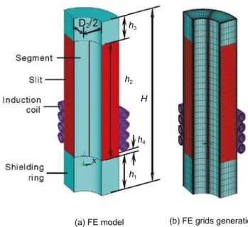
1.1 FE model
1.2 Model dimensions
The dimension of prototype crucible is listed in Table 1, and the parameters include: height of bottom (h1), slit length (h2),
height of upper shield ring (h3), total crucible height (H), outer
Shielding ring Calculation domain
Slit
Segment midpoint
Induction coil Segment
Fig. 1: Schematic diagram of bottomless type EMCC with four-turn induction coil
Fig. 2: 3-D calculation model of EMCC and four-turn induction coil
Table 1: Coniguration dimensions of prototype EMCC
Coniguration elements h1 h2 h3 h4 H D1 D2 d
Levels (mm) 30 100 20 3 150 60 30 1
Table 2: Physical properties of materials used in 3-D FE models
Materials Induction coil Cold crucible Air Resistivity (Ω·m) 1.673e-8 1.8e-8
Relative permeability (μr) 1 1 1
The EM energy in EMCC concentrates mainly near the crucible inner rim due to the skin effect of the melt; therefore in this study, the slit and the segment midpoint on the crucible inner rim were selected to calculate the magnetic lux density Bz, which are also highlighted in Fig. 1.
1.3 Governing equations and solution method
The copper crucible and the induction coil in FE models are considered as conductor region and the air is considered as non-conductor region. We assume that the permeability (μ) of all materials is a constant with value of 1.0. Therefore, M a x w e l l ’ s e q u a t i o n s g o v e r n i n g t h e t i m e - d e p e n d e n t electromagnetic ield at a lower frequency are given as:
(1) (2)
(3)
where, H is the magnetic ield intensity, E is the electric ield intensity, B is the magnetic lux density and A is the magnetic vector potential. In view of that the magnetic field is a curl ield, the function of scalar potential can not be applied in the conductor region. However, H can be described as a gradient of a scalar quantity in a free space (such as air):
(4)
The magnetic scalar potential φm has been adopted in FE
models for saving calculation time and reducing the usage of computational memory. To solve A and φm in the divergence
and curl field, Alembert equation with dynamic potential function can be rewritten as:
(5)
(6)
where, ε is the permittivity. When the ield source J (current intensity) and ρ (charge density) are given, A and φ can be solved and then B and E can be consequently solved using equations (2) and (3).
and inner diameter (D1 and D2), position of induction coil (h4),
and slit width (d). Further, a series of 3-D FE models were established with only one dimensional parameter varying at a time. Table 2 summarizes physical properties of materials used in FE models.
(a) FE model (b) FE grids generation
h3
h2
h4
h1
2 Results and discussion
2.1 Comparison of measured and calculated
results
In order to verify the numerical modeling and FE calculation, experimental magnetic ield measurements at the cold crucible center were compared with the 2-D [6] and a 3-D FE models.
The experimental and calculated (both 2-D and 3-D) results of Bz are shown in Fig. 3, which indicates that Bzcalculated using
a 2-D FE model is comparably higher than that measured, whereas the calculated Bz using a 3-D model is in good
agreement with the experimental results. The discrepancy between the 2-D calculation and the measurement might be due to the fact that the configuration of the segment and its shielding effect were neglected. It can therefore be concluded that the distribution of the magnetic ield in cold crucible can be precisely calculated by a 3-D FE model, and we applied 3-D FE model in this study.
2.2 Effect of power parameters and induction
coil on magnetic ield
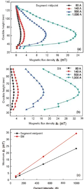
2.2.1 Current intensity
Bz under different current intensities but at a constant
frequency of 50 kHz were calculated, the results are shown in Fig. 4. It can be seen clearly from Fig. 4 that Bz increases
monotonically with the current intensity both at the segment midpoint and the slit location, and Bz reaches the maximum
value at the height of 60 mm which corresponds to the second turn of the induction coil (refer to Fig. 1). At the same height, Bz at the slit is about 1.5 times higher than that
at segment midpoint due to a higher EM transparency at the slit. Moreover, Figure 4 (c) indicates that the maximum of Bz
increases linearly with current intensity. It has been reported in Ref. [13] that a reasonable amount of molten material can be obtained under a critical current intensity, below which the melt will not form. Thus, the coil current must be increased enough for supplying the necessary energy to stabilize the melt at lower frequency. A recent research also reported that the meniscus shape gradually changes from concavity to convexity
Fig. 3: Comparison of Bz between experimental measurements
and the calculation results at crucible centre
Fig. 4: Effect of current intensity on Bz in cold crucible:
(a) at segment midpoint; (b) at slit; (c) maximum Bz
with the increasing of current intensity [14].
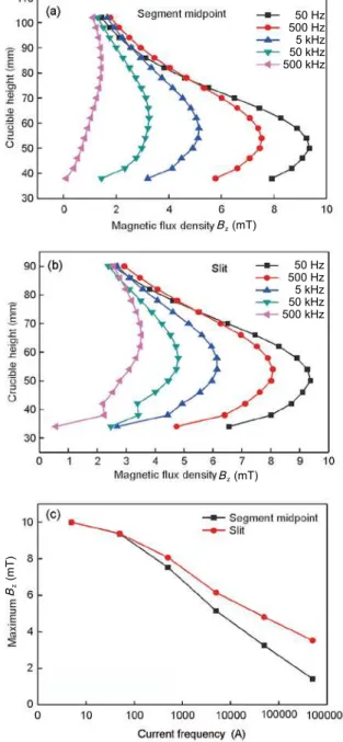
2.2.2 Current frequency
Under a constant current intensity of 140 A, Bz in EMCC as
a function of current frequency was calculated and the results are shown in Fig. 5. It can be seen from Fig. 5 (a) and Fig.5 (b) that the distribution of Bz at the segment midpoint and the slit
looks similar, Bz at both locations increases with the decreasing
of frequency. This phenomenon agrees with a previous study as reported in Ref. [15]. It is well known that a higher frequency leads to weaker EM penetration through the crucible wall due to the shielding effect by copper segment, thus a lower frequency is beneicial to EM penetration. Figure. 5 (c) shows that the maximum of Bz at the segment and at the slit is
almost equal at a frequency below 50 kHz, with the increasing of frequency, the difference between maximum Bz at the
segment midpoint and the slit increases gradually. Therefore, Bz in the cold crucible can have more uniform intensity
distribution by reducing the current frequency properly.
36
Fig. 6: Effect of h4 on Bz in cold crucible: (a) at segment
midpoint; (b) at slit; (c) maximum Bz
However, a low frequency leads to a weak power absorption in the melt, and therefore causes an unsuccessful skull melting, this situation has been discussed in Ref. [9] in details. The choice of the frequency should consider the inluences of both meniscus and EM penetrability [7] through crucible wall. As a rule of thumb, the operating frequency should be chosen to be equal or slight higher than the critical frequency in order to obtain the maximum power for a speciic EMCC system.
2.2.3 Position of induction coil
It was previously reported [15-16] that the position of the induction coil is also critical in governing the magnetic ield in the cold crucible, and the maximum Bz becomes smaller if the
induction coil is placed at a lower position.
Under a constant current density of 1,000 A and frequency of 10 kHz, h1 and h4 were varied to explore the effect of the gap
between the induction coil and the shielding ring on Bz, and the
Fig. 5: Effect of frequency on Bz in cold crucible:
(a) at segment midpoint; (b) at slit; (c) maximum Bz
results are shown in Fig. 6. Figures 6 (a) and 6 (b) show that Bz
decreases signiicantly when the shield ring moves closer to the induction coil (i.e. h4 decreases). When h4 increases from 3 mm
to 18 mm, the maximum value of Bz is increased by about 25%,
as presented by the curves in Fig. 6 (c). The similarity of h4
-dependent Bz variation at the segment midpoint and at the slit,
can be partly explained by the shielding effect. It is therefore proposed that when a suficiently high temperature gradient (GT)
is considered during DS using EMCC, a large h4 can reduce
effectively the power loss.
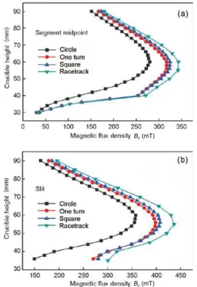
2.2.4 Section shape of induction coil
It has a long debate on the effect of cross sectional design of induction coil and its effect on the magnetic ield. In this study, Bz was calculated accordingly based on different copper
induction coil design, namely circular, square, one turn and racetrack, the results are shown in Fig. 7. It can be clearly seen from Fig. 7 that the induction coil with racetrack section has
h1 = 30, h4 = 3
h1 = 27, h4 = 6
h1 = 21, h4 = 12
h1 = 15, h4 = 18
h1 = 30, h4 = 3
h1 = 27, h4 = 6
h1 = 21, h4 = 12
h1 = 15, h4 = 18
h4
Bz (mT)
Bz (mT)
Bz
(mT)
Bz (mT)
Bz (mT)
50 Hz 500 Hz 5 kHz 50 kHz 500 kHz
3 Conclusions
A 3-D finite element (FE) method based on experimental veriication was applied to calculate the magnetic lux density Bz, and the calculated Bz were in good agreement with the
experimental results. The effects of power parameters, location of the induction coil and sectional design of copper coil on Bz at the segment midpoint and at the slit were numerically
evaluated.
(1) Bz at both the segment midpoint and the slit increases
with the increasing of current intensity, or the decreasing of current frequency, the maximum Bz at the slit is apparently
higher than that at the segment midpoint.
(2) Due to the shielding effect, a close spacing between the shield ring and the induction coil negatively impacts Bz.
(3) The induction coil with racetrack section shows the optimal performance for increasing Bz, and such a design is
promising in industrial applications.
an optimal performance with the increasing of Bz both at the
segment midpoint (Fig. 7a) and at the slit (Fig. 7b). Obviously, under the same power parameters, the induction coil with circle section results in the lowest value of Bz, and Bz induced
from the coil with square shape is slightly higher than that with one turn rectangular coil, but both have relatively weaker Bz than that with a racetrack section. It is anticipated that such
a result can provide a good guidance for industrial design and application.
Fig. 7: Effect of section shape of induction coil on Bz in
cold crucible: (a) at segment midpoint and (b) at slit
This research was financially supported by the National Basic Research Program of China (Grant No. 2011CB605504).
References
[1] Cha P R, Hwang Y S, Nam H S, et al. 3D numerical analysis on electromagnetic and luid dynamic phenomena in a soft contact electromagnetic slab caster. ISIJ International, 1998, 38(5): 403-410.
[2] Ding Hongsheng, Chen Ruirun, Guo Jingjie, et al. Directional solidiication of titanium alloys by electromagnetic coninement in cold crucible. Materials Letters, 2005, 59(7): 741-745. [3] Durand F. The electromagnetic cold crucible as a tool for melt
preparation and continuous casting. International Journal of
Cast Metals Research, 2005, 18(2): 93-107.
[4] Bewlay B P, Reeder W J, Lipsitt H A, et al. Toughness Enhancements in Intermetallic-Based Composites: Processing and Properties. In: Proceedings of Processing and Fabrication of Advanced Materials for High Temperature Application IV(TMS, Warrendale, PA), 1996: 371-383.
[5] Chen Ruirun, Ding Hongsheng, Guo Jingjie, et al. Process on cold crucible electromagnetic casting for titanium alloy. China Foundry, 2007, 4(3): 190-193.
[6] Fu Hengzhi, Ding Hongsheng, Chen Ruirun, et al. Directional solidification technology based on electromagnetic cold crucible to prepare TiAl intermetallics. Rare Metal Materials and Engineering, 2008, 37(4): 565-570.
[7] Westphal E, Milhlbauer A and Muiznieks A. Calculation of electromagnetic fields in cylindrical induction systems with slitted metallic walls. Electrical Engineering, 1996, 79(4): 251-263.
[8] Westphal E, Muiznieks A and Muhlbauer A. Electromagnetic ield distribution in an induction furnace with cold crucible. IEEE Transactions on Magnetics, 1996, 32(3): 1601-1604.
[9] Gross C, Assmus W, Muiznieks A, et al. Power consumption of skull melting, part I: Analytical aspects and experiments. Crystal Research and Technology, 1999, 34(3): 319-328.
[10] Gombert D, Richardson J R. Cold-crucible induction melter design and development. Nuclear Technology, 2003, 141(3): 301-308.
[11] Umbrasko A, Baake E and Nacke B. Numerical studies of the
melting process in the induction furnace with cold crucible. COMP- The International Journal for Computation and
Mathematics in Electrical and Electronic Engineering, 2008, 27(2): 359-368.
[12] Makino H, Kuwabara A and Asai S. Process analysis of
non-contact continuous casting of materials using cold crucible. ISIJ
International, 1996, 36(4): 380-387.
[13] Muiznieks A, Raming G and Muhlbauer A. Power consumption of skull melting, part II: Numerical calculation of the shape of the molten zone and comparison with experiment. Crystal Research and Technology, 1999, 34(3): 329-338.
[14] Zhang Z F, Xu J, Tian Z F, et al. The continuous casting of a semisolid aluminum alloy billet with a multiple magnetic field imposed. Journal of Ceramic Processing Research, 2006, 7(2): 152-155.
[15] Cho Y W, Oh Y J, Yi K W, et al. Numerical analysis of molten metal shape in cold crucibles by 3D FEM. Modelling and Simulation in Materials Science and Engineering, 1996, 4(1):
11-22.
[16] Cha P R, Hwang Y S, OH Y J, et al. Numerical analysis on cold crucible using 3D H-phi method and inite volume method with non-staggered BFC grid system. ISIJ International, 1996, 36(9):
1157-1165. Bz (mT)