Vol. 6, No. 2, November 2009, 253-265
Design Parameter Based Method of
Partial Discharge Detection and
Location in Power Transformers
Annadurai Santosh Kumar
1, Ram Prakash Gupta,
Athikkan Venkatasami, Kodhandaraman Udayakumar
Abstract: Insulation defect detection in time ensures higher operational reliabi-lity of power system assets. Power transformers are the most critical unit of power systems both from economical and operational front. Hence it becomes necessary to have knowledge of the actual insulation condition of transformer to increase dependability of the system. The performance and ageing of the transformer insulation is mainly affected by Partial discharges (PD). Proper diagnosis in terms of amplitude and location of partial discharge in a power transformer enables us to predict well in advance, with much confidence, the defect in insulation system, which avoids large catastrophic failures.
In this work a 20kVA, 230/50kV single phase core type transformer is used for evaluation of the transfer function-based partial discharge detection and location using modeling of the winding, using design data. The simulation of capturing on-line PD pulses across the bushing tap capacitor is done for various tap positions. Standard PD source model is used to inject PD pulse signal at 10 tap locations in the winding and corresponding response signatures are captured at the bushing tap end (across 1000pF). The equivalent high frequency model of the winding is derived from the design parameters using analytical calculations and simulations in packages such as MAGNET and ANSOFT. The test conditions are simulated using ORCAD-9 and the results are evaluated for location accuracy using design parameter based PD monitoring method.
Keywords: Power transformers, Partial discharge detection, Insulation defect detection, Design parameters.
1 Introduction
Partial discharges (PD) are localized electrical breakdowns within the insulation, which do not bridge the end electrodes. During the occurrence of PD, energy dissipation takes place and can be attributed to various kinds of generated signals such as electrical current pulses through earth, voltage drop across electrodes, electromagnetic radiations, optical signal and acoustic energy
1CMDRC, CG Global R&D Centre, Crompton Greaves Ltd., Kanjur Marg (E), Mumbai, India. 400 042;
emission simultaneously. Furthermore, PD is also attributed to post effect which is reflected in chemical property of insulation oil (Dissolved Gas Analysis). PD measurements can be conducted either continuously or intermittently, on-line or off-line. PD results are a reliable source to assess the health of electrical equipment and to plan for maintenance.
Acoustic Emission (AE) PD detection method is based on the fact that partial discharges produce acoustic waves in a frequency range up to 150 kHz within the transformer tank [1]. Special piezo-electric sensors are placed on the outer surface of the transformer tank in order to detect these waves that propagate from the PD source to tank through dielectric medium. AE method is usually sensitive to PD level of above 500pC [2]. The optical method uses multiple fibre optic cables placed at various PD prone locations, which increases complexity and decreases reliability. Ultra high frequency (UHF) PD detection method detects radiated electromagnetic waves in the frequency range of 0.3–3GHz for detecting discharges in power transformers [3, 4, 5]. A major difficulty of this method is the suppression of noise and external disturbances that are similar to the PD signal, which affect the accuracy and sensitivity of detection [18].
Electrical PD detection methods are classified as conventional off-line methods [2], which measure apparent charge quantity using conventional PD measuring circuitry and instruments with a centre frequency of 500kHz and 250kHz for narrowband method and wideband methods respectively [10]. PD type and location can be determined by analyzing the shape of the captured PD signal in time domain. The other electrical method, which is preferable for on-line monitoring, captures the earth current and bushing current signals propagated along the winding height. Recent developments in electrical methods are based on the fact that while a discharge signal propagates from the location to the measuring terminals, the terminal response acquires the information on the location of the PD source. The PD type and location can be determined by frequency spectrum analysis of the captured signal.
2 Theoretical
Background
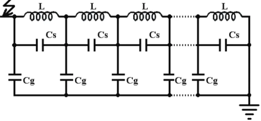
Considering the mathematical model of a single layer transformer winding shown in Fig. 1, high frequencies in the measurement are due to the capacitance present between transformer windings and earthed parts (core, tank, etc.), within each winding, between discs, turns and layers, and between individual coils. Owing to this capacitance the voltage distribution of steep-front over voltages within the transformer will not be uniform [19, 21]. A section of the model two of its element, each of its length dx, the inductance of each element is denoted by L [H/m], its shunt capacitance by Cg [F/m], and its series capacitance by
s
Fig. 1 – Mathematical model of a single layer transformer winding at high frequencies.
In the low frequency range, the signal travels through the equivalent transmission line of the winding with a finite propagation velocity. The time delay between the two terminal signals depends on the position of the PD source relative to the terminals. This time delay can be used for location and such a technique is called the travelling wave method. In the higher frequency range, the capacitive ladder network applies. The ratio of the two terminal signal magnitudes can be used for location. This is called the capacitive ratio method. From the previous works on the PD location using the series resonant frequencies the equation is given as:
2 2 0 1 4 1 2 s g f LC n x f LC − π
= − , (1)
where:
0
x – location PD along the winding height (p.u.);
n – order of series resonant frequency considered;
f – value of the series resonant frequency [Hz].
Equation (1) can be used to calculate the location of the PD source when the frequency of a series resonance of the line-end discharge signal (f) and its order (n) is known, provided that LCg and LCs values of the equivalent circuit of winding are also known. Equations (2) and (3) shows that if two series resonances f1 and f2 can be obtained corresponding to n1 and n2, then LC
and LK can be found for the equivalent circuit of the winding and are given by
(
)
(
)
2 1 2 2 2 2 2 1 2 2 1 1 1 4 g n n LC f f n n ⎛ ⎞ = ⎜ − ⎟(
)
2 2
2 1
2 2 2
2 1 2 1 1 4 s n n LC f f n n ⎡⎛ ⎞ ⎛ ⎞ ⎤ ⎢ ⎥ = ⎜ ⎟ −⎜ ⎟
π − ⎢⎣⎝ ⎠ ⎝ ⎠ ⎥⎦. (3)
3 Performed
Work
In this work a 20kVA, 230V/50kV, transformer was designed for the experimentation with 10 accessible taps on the HV to facilitate injection of PD across the winding height. The design parameters are as follows:
LV winding:
Type of winding: Layer No. of layers: 2
Total No. of turns: 92 No. of turns / layer: 46
Insulation between turn = 0.4mm Inner Diameter: 119mm
Outer Diameter: 145mm
Electrostatic shield (copper foil):
Inner Diameter: 210mm Outer Diameter: 211mm
HV winding:
Type of winding: Crossover coils No. of crossover coils: 10
No. of turns / coil: 2000 No. of Layer / coil: 53 No. of Turns / Layer: 38 Inner Diameter: 212mm Outer Diameter: 288mm
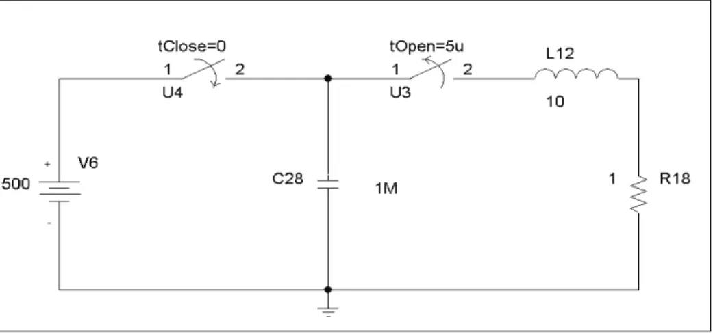
are simulated for the test condition i.e., PD signals are injected at various tap positions and corresponding bushing end current signals are captured for analysis the snapshot of the simulation is as shown in Fig. 3. The accuracy of the location algorithm in term of percentage height of winding is evaluated and compared.
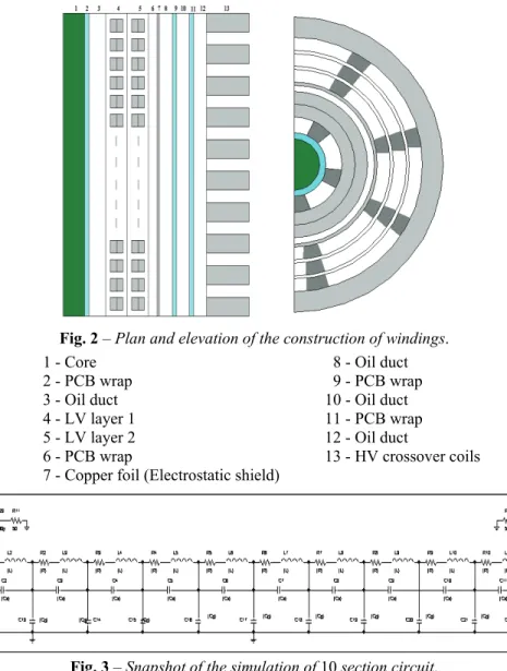
Fig. 2 – Plan and elevation of the construction of windings.
1 - Core 8 - Oil duct
2 - PCB wrap 9 - PCB wrap
3 - Oil duct 10 - Oil duct
4 - LV layer 1 11 - PCB wrap
5 - LV layer 2 12 - Oil duct
6 - PCB wrap 13 - HV crossover coils 7 - Copper foil (Electrostatic shield)
Fig. 3 – Snapshot of the simulation of 10 section circuit.
Fig. 4 – PD signal generator.
4
High Frequency Model
The lumped parameters for the HV winding are as shown in the Table 1. DC Resistance of the winding was done by knowing the design parameters and the resistivity of the conductor used.
Table 1
High frequency model lumped parameters.
Parameter Analytical results Simulation results
g
C 1.946 × 10⁻¹¹ 1.99 × 10⁻¹¹
s
C 3.11966 × 10⁻¹¹ 3.0108 × 10⁻¹¹
L 2.075 H 1.47 H
R 1.6366 × 10⁻⁴ Ώ 1.6366 × 10⁻⁴ Ώ
Mutual inductances have been considered in the simulation using the coupling coefficients.
5
Results and Discussions
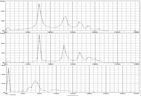
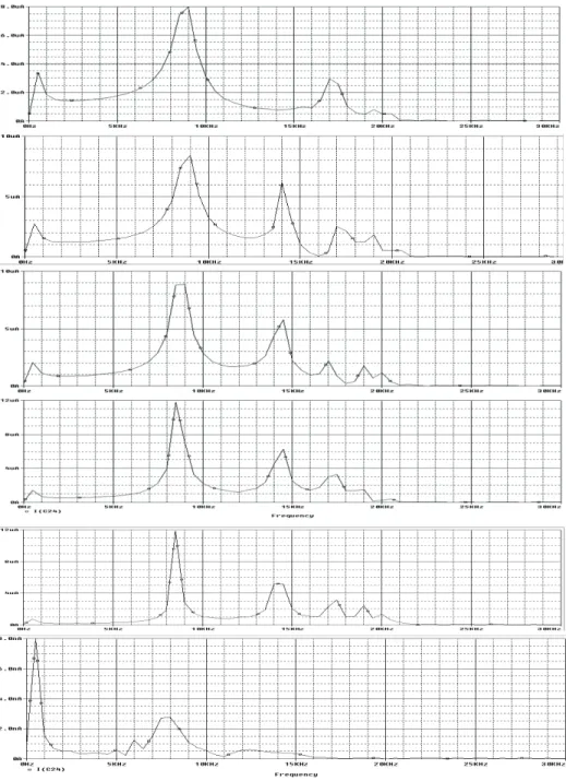
In first simulation, analytically calculated lumped parameters are simulated in ORCAD, and FFT of the captured bushing current signals for various PD locations are taken. Their corresponding frequency for peaks and troughs is used for the PD location estimation. Fig. 4 illustrates the FFT of various signals captured at bushing tap.
Fig. 4 – FFT of the PD signal captured at bushing tap
for various PD source locations for analytically calculated parameters.
Table 2
Series resonant frequencies of the signals captured at bushing tap for input at all taps.
PD Location Algorithm
Series resonance frequencies PD Location
F1 F2 F3 F4 Line end 8 14 17.5 19
Tap 1 9 15 18
Tap 2 10 16 19
Tap 3 11.4 17.4 19.5 Tap 4 13.5 19 20.5 Tap 5 15.5 17.5 20 Tap 6 16 17 19.5 Tap 7 17.5
Tap 8 18 19.5 20.5 Tap 9
Table 3
Lumped parameters derived from series resonance peaks. Value of LK and LC from resonances f1 and f2 of Line end signal
s
LC 3.50765E-09
g
Table 4
Estimation of PD location using series resonance peaks. Comparison between actual and measured PD Location
Tap No
Actual PD position
[%]
Estimated position due to F1 [%]
Actual Height
Measured height
Error in mm
Error in % height of winding
Bush 0 0 0 0 0 0
Tap 1 10 12.463 36 44.8668 8.8668 2.463 Tap 2 20 22.599 72 81.3564 9.3564 2.599 Tap 3 30 34.062 108 122.6232 14.6232 4.062 Tap 4 40 47.328 144 170.3808 26.3808 7.328 Tap 5 50 57.219 180 205.9884 25.9884 7.219 Tap 6 60 59.408 216 213.8688 -2.1312 -0.592 Tap 7 70 65.49 252 235.764 -16.236 -4.51 Tap 8 80 67.39 288 242.604 -45.396 -12.61
Tap 9 90 ND 324 ND ND ND
Fig. 5 – FFT of the PD signal captured at bushing tap
for various PD source locations for analytically simulated parameters.
Table 5
Series resonance frequencies of the signals captured at bushing tap for input at all taps.
PD Location Algorithm
Series resonance frequencies PD Location
F1 F2 F3 F4 Line end 9.5 15 18 20
Tap 1 10 15.5 18.6 Tap 2 11.5 16.6 18 Tap 3 12.5 16 18 Tap 4 14 18.5 19 Tap 5 15.5 18.5 Tap 6 16 18 19.5 Tap 7 18.5 20
Tap 8 19.6 19.5 Tap 9 19.6
Table 6
Lumped parameters derived from series resonance peaks.
Value of LK and LC from resonances f1 and f2 of Line end signal
s
LC 2.21196E-09
g
LC 5.65494E-11
Table 7
Estimation of PD location using series resonance peaks. Comparison between actual and measured PD Location
Tap No. Actual PD position [%] Estimated position due to F1 [%]
Actual Height Measured Height Error [mm] Error in % height of winding
Bush 0 0 0 0 0 0
6 Conclusion
The propagation of partial discharge pulses in the HV winding is analyzed based on the change in PD location. The high frequency model of the transformer was derived using both analytical calculation and simulations within an accuracy of ±5%. Calculation of PD location using the sectional transfer function from the design parameter gave PD location within accuracy of ±10% of the winding height. Maximum variation and error is noticed nearer to the neutral end as the resonant peaks are not prominent enough.
7 References
[1] A. Akbari, P. Werle, H. Borsi, E. Gockenbach: Transfer Function-based Partial Discharge Localization in Power Transformers: A Feasibility Study, IEEE Electrical Insulation Magazine, Vol. 18, No. 5, Sep./Oct. 2002, pp. 22 – 32.
[2] M. Gopalakrishnan, M.A. Panneerselvam, R.B. Sreeshankar, S. Jayalalitha, V. Jayashankar: Location of partial discharges in transformers, Annual Report Conference on Electrical Insulation and Dielectric Phenomena, 19-22 Oct. 2003, pp. 620 – 623.
[3] High-voltage Test Techniques – Partial Discharge Measurements, British Standard BS EN 60270:2001, IEC60270:2000, 2001.
[4] High-voltage Test Techniques – Partial Discharge Measurements, IEC standard 60270,
Third Edition, 2000.
[5] IEEE Guide for the Detection and Location of Acoustic Emissions from Partial Discharges in Oil Immersed Power Transformers and Reactors, IEEE C57.127-2007 (Revision of IEEE Std C57.127-2000).
[6] M.D. Judd, B.M. Pryor, S.C. Kelly, B.F. Hampton: Transformer Monitoring Using the UHF Technique, International Symposium on High Voltage Engineering, London, UK, 1999, Vol. 5, pp. 362 – 365.
[7] H. Borsi, P. Werle, E. Gockenbach: Various Partial Discharge Measurement and Evaluation Techniques Adapted to Different Transformer Types, University of Hannover, Germany, January 2002.
[8] P. Werle, A. Akbari, E. Gockenbach, H. Borsi: An Enhanced System for Partial Discharge Diagnosis on Power Transformers, International Symposium on High Voltage Engineering, Rotterdam, Netherlands, 2003.
[9] D. Konig, Y.N. Rao: Partial Discharges in Electrical Power Apparatus, VDE-Verlag GmbH, Berlin, 1993.
[10] S. Xu, S.D.Mitchell, R.H. Middleton: Partial Discharge Localization for a Transformer Based on Frequency Spectrum Analysis, Australasian Universities Power Engineering Conference, Christchurch, New Zealand, 28. Sept.-1. Oct. 2003.
[11] M.A.A. Rahman, H. Hashim, P.S. Ghosh: Frequency Response Analysis of a Power
Transformer, Australasian Universities Power Engineering Conference, Christchurch, New Zealand, 28. Sept.-1. Oct. 2003.
[13] M. Hassig, R. Braunlich, R. Gysi, J.J. Alff, V. der Honhanessian, W.S. Zaengl: On-site Application of Advanced Diagnosis Methods for Quality Assessment of Insulation of Power Transformers, Conference on Electrical Insulation and Dielectric Phenomena, Piscataway, NJ, USA, , 14-17 Oct. 2001, pp. 441 – 447.
[14] J. Giddens, H. Edin, U. Gafvert: Measuring System for Phase Resolved Partial Discharge Detection at Low Frequencies, International Symposium on High Voltage Engineering, London, UK, 1999, Vol. 5, pp. 228 – 231.
[15] S.N. Hettiwatte, P.A. Crossley, Z.D. Wang, A. Darwin, G.Edwards: Simulation of a Trans-former Winding for Partial Discharge Propagation Studies, IEEE Power Engineering Society Winter Meeting, 2002, Vol. 2, pp. 1394 – 1399.
[16] S.N. Hettiwatte, P.A. Crossley, Z.D. Wang, A. Darwin, G.Edwards: Experimental
Investigation into the Propagation of Partial Discharge Pulses in Transformers, IEEE Power Engineering Society Winter Meeting, 2002, pp. 1372 – 1377.
[17] Z.D. Wang, P.A. Crossley, K.J. Cornick, D.H. Zhu, A.J. Shields, I.J. Kemp: Partial Dis-charge Location in Power Transformers, IEE Proceedings on Science, Measurement and Technology, Vol. 147, No. 5, Sept. 2000, pp. 249 – 255.
[18] F.H. Kreuger: Discharge Detection in High Voltage Equipment, Heywood Book, London, 1964.
[19] K. Karsai, D. Kerenyi, L. Kiss: Large Power Transformers, ELSEVIER, Amsterdam, 1987. [20] H.S. Carslaw, J.C. Jaeger: Operational Methods in Applied Mathematics, Dover Books,
1977.
[21] B. Heller, A. Veverka: Surge Phenomena in Electric Machines, Academia Publishing House of the Czechoslovak Academy of sciences, Prague, 1968.
[22] F.W. Grover: Inductance Calculations: Working Formulas and Tables, Dover Publications, 2004.
[23] M.S. Naidu, V. Kamaraju: High Voltage Engineering McGraw-Hill, 2004.
[24] P. Werle, H. Borsi, E. Gockenback: A New Method for Partial Discharge Location on Power Transformer based on a System Theoretical Approach, International Conference on Properties and Applications of Dielectric Materials, 2000, Vol. 2, pp. 831 – 834.
[25] Partial Discharges in Transformer Insulation, CIGRE WG 15-302, Session 2000.