High Performance VLSI Design Using Body Biasing
in Domino Logic Circuits
Salendra.Govindarajulu1, Dr.T.Jayachandra Prasad2 1Associate Professor, ECE, RGMCET, JNTU
2Principal, RGMCET, JNTU
Abstract— Dynamic domino logic circuits are widely used in modern digital VLSI circuits. These dynamic circuits are often favoured in high performance designs because of the speed advantage offered over static CMOS logic circuits. The main drawbacks of dynamic logic are a lack of design automation, a decreased tolerance to noise and increased power dissipation. Dynamic CMOS circuits, featuring a high speed operation are used in high performance VLSI designs. In this work, different types of AND gates with Conventional Body Bias & Forward Body Bias inverters are compared with their performances and the high performance circuit was specified. The different design styles are compared by performing detailed transistor-level simulation on bench mark circuits using CAD tools of DSCH3 and Microwind3 in sub-micron regime. The simulated results are compared in terms of power dissipation, propagation delay, PDP and area.
Index Terms—CMOS, Conventional Body Bias, Domino logic, Dynamic power, Forward Body Bias, Full-swing.
I. INTRODUCTION
The power consumed in high performance microprocessors has increased to levels that impose a fundamental limitation to increasing performance and functionality [1]–[3]. If the current trend in increasing power continues, high performance microprocessors will soon consume thousands of watts. The power density of a high performance microprocessor will exceed the power density levels encountered in typical rocket nozzles within the next decade [2]. The generation, distribution, and dissipation of power are at the forefront of current problems faced by the integrated circuit industry [1]– [5]. The application of aggressive circuit design techniques which only focus on enhancing circuit speed without considering power is no longer an acceptable approach in most high complexity digital systems. Dynamic switching power, the dominant component of the total power consumed in current CMOS technologies, is quadratically reduced by lowering the supply voltage. Lowering the supply voltage, however, degrades circuit speed due to reduced transistor currents. Threshold voltages are scaled to reduce the degradation in speed caused by supply voltage scaling while maintaining the dynamic power consumption within acceptable levels [1]–[5]. At reduced threshold voltages, however, subthreshold leakage currents increase exponentially. Energy efficient circuit techniques aimed at lowering leakage currents are, therefore, highly desirable. Domino logic circuit techniques are extensively applied in high performance
microprocessors due to the superior speed and area characteristics of domino CMOS circuits as compared to static CMOS circuits [7]–[8]. However, deep sub micrometer (DSM) domino logic circuits utilizing low power supply and threshold voltages have decreased noise margins [9]–[11]. As on-chip noise becomes more severe with technology scaling and increasing operating frequencies, error free operation of domino logic circuits has become a major challenge [9], [10], [11].
The focus of this paper is to implement different types of AND gates with Conventional Body Bias & Forward Body Bias inverters and they are compared with their performances. The organization of the paper is as follows. A brief review of the sources of power dissipation in CMOS circuits is provided in Section II. In Section III various Circuit techniques in domino logic circuits for power reduction and delay reduction are proposed. In Section IV simulation and implementation results are presented. Finally, conclusions are presented in Section V.
II. SOURCESOFPOWERDISSIPATION
The power consumed by CMOS circuits can be classified into two categories:
A. Dynamic Power Dissipation
For a fraction of an instant during the operation of a circuit, both the PMOS and NMOS devices are “on” simultaneously. The duration of the interval depends on the input and output transition (rise and fall) times. During this time, a path exists between Vdd and Gnd and a short-circuit current flows.
However, this is not the dominant factor in dynamic power dissipation. The major component of dynamic power dissipation arises from transient switching behavior of the nodes. Signals in CMOS devices transition back and forth between the two logic levels, resulting in the charging and discharging of parasitic capacitances in the circuit. Dynamic power dissipation is proportional to the square of the supply voltage. In deep sub-micron processes, supply voltages and threshold voltages for MOS transistors are greatly reduced. This, to an extent, reduces the dynamic power dissipation. B. Static Power Dissipation
length and oxide thickness. It varies exponentially with threshold voltage and other parameters. Reduction of supply voltages and threshold voltages for MOS transistors, which helps to reduce dynamic power dissipation, becomes disadvantageous in this case. The subthreshold leakage current increases exponentially, thereby increasing static power dissipation.
III. CIRCUIT TECHNIQUES
Dynamic domino logic circuits are widely used in modern VLSI circuits. These dynamic circuits are often favoured in high performance designs because of the speed advantage offered over static CMOS logic. The main drawbacks of dynamic logic are a lack of design automation, a decreased tolerance to noise and increased power dissipation. This work discusses several domino circuit design techniques to reduce the power dissipation of domino logic while simultaneously improving noise immunity.
Forward body biasing can be used to reduce threshold voltage and improve system speed. However, as threshold voltage is decreased through body biasing, sub-threshold leakage increases. In the case where PMOS pre-charge transistor bodies are also connected to the clock, the variation in threshold voltage is such as to yield low pre-charge time and leakage.The dynamic node of a domino gate is susceptible to charge loss due to leakage and charge redistribution, with consequent reduction in dynamic node voltage. Charge sharing can be addressed by connecting a charge restoring keeper device to the dynamic node. The keeper addresses both leakage and charge sharing but increases capacitance, reducing speed and increasing power consumption. Alternatively, internal nodes can be pre-charged. This approach however is not effective against leakage.
Fig.1.CMOS inverter with conventional body bias
Fig2.CMOS inverter with forward body bias
Speed comparison:
A number of choices can be made for the static output inverter of domino gates, permitting designs that strike a balance between speed and power dissipation. The above Fig.1&2 show schematic for static CMOS inverters using conventional-body biasing and forward body biasing.
Five body biasing schemes, labeled A through E, for the evaluation networks are shown in Fig.3. Techniques for domino circuits operating in the sub threshold region are presented. Comparison of body biasing methods using delay, power and PDP indicates that separately biasing the precharge and evaluation tree transistor bodies permits high speed and energy-efficient ultra-low voltage domino circuits to be realized. In addition, forward biasing the NMOS transistors in the evaluation tree can reduce both delay and PDP. Minimum energy in the sub threshold region then depends not only on supply voltage but also on the sub threshold bias voltage.
Type A
Type B
Type C
Type D
Type E
DIFFERENT TYPES
OF CMOS DOMINO
AND GATES
Fig.3. Different types of CMOS domino AND gates
Performance of domino gates depends on the properties of the output inverter, which dominates power dissipation for low fan-in gates. A pseudo NMOS output inverter yields high speeds but consumes more power than conventional static CMOS with zero body bias. A forward body-biased static CMOS output inverter, on the other hand, yields significant reduction in power-delay product compared to similarly biased pseudo-NMOS inverter at moderate frequencies and low activities.
particularly for large fan-in gates at moderate frequencies; these two methods together provide a balanced trade-off among power, delay and robustness.
Sensitivity to discharge the dynamic node is strongly dependant on body biasing, forward body-biasing NMOS evaluation transistors increases charge sharing compared to zero body-biasing. In addition, clock feed through effects are most significant in dynamic biasing schemes in which both PMOS and NMOS bodies are connected to the clock signal. By inter connecting the all types of CMOS and gates with both Conventional Body Bias and Forward Body Bias circuits we can get 10 types of circuits.
Finally all these circuits are compared with their power dissipation, delay and power delay product values, the Type-E circuit connected with Forward Body Bias circuit is shown less power delay product value i.e. this circuit offers high performance value when comparing with the remaining circuits. In Fig .4 Type A-CBB and2 is shown and in Fig.5 Type A-FBB and2 is shown.
Fig.4 Type A-CBB
Fig.5 Type A-FBB
IV.SIMULATION AND IMPLEMENTATION RESULTS
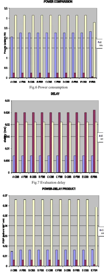
By inter connecting the all types of CMOS and2 gates with both Conventional Body Bias and Forward Body Bias circuits we can get 10 types of circuits. The different design styles are compared by performing detailed transistor-level simulation on bench mark circuits using CAD tools of DSCH3 and Microwind3 in sub-micron regime. Finally all these circuits are compared with their power dissipation, delay and power delay product values, the Type-E circuit connected with Forward Body Bias circuit is shown less power delay product value i.e. this circuit offers high performance value when comparing with the remaining circuits. Table1 shows the power consumption of the 10 circuits. Fig.6 shows the bar diagram of the power consumption. Table2 shows the evaluation delay of the 10 circuits. Fig.7 shows the bar
diagram of the evaluation delay. Table3 shows the power delay product of the 10 circuits. Fig.8 shows the bar diagram of the power delay product.
Fig.6 Power consumption
Fig.7 Evaluation delay
Comparison of all types of AND gates:
Table1. Power consumption A
CBB A FBB
B CBB
B FBB
C CBB
C FBB
D CBB
D FBB
E CBB
E FBB
POWER (Micro
Watt)
2.061 2.255 2.255 2.255 2.255 2.255 2.255 2.255 2.255 2.326 45 nm
0.242 0.242 0.242 0.242 0.242 0.242 0.242 0.242 0.242 0.055 65 nm
3.143 3.143 3.143 3.143 3.143 3.143 3.143 3.143 3.143 2.784 120nm
Table2.Evaluation delay A
CBB A FBB
B CBB
B FBB
C CBB
C FBB
D CBB
D FBB
E CBB
E FBB
DELAY (nano sec)
0.007 0.007 0.007 0.007 0.007 0.007 0.007 0.007 0.007 0.007 45 nm
0.025 0.025 0.025 0.025 0.025 0.025 0.025 0.025 0.025 0.026 65 nm
0.021 0.021 0.021 0.021 0.021 0.021 0.021 0.021 0.021 0.021 120 nm
Table3.Power delay product A
CBB
A FBB
B CBB
B FBB
C CBB
C FBB
D CBB
D FBB
E CBB
E FBB
PDP
(μW * ns)
0.014 4
0.015 7
0.0157 0.015 7
0.0157 0.0157 0.0157 0.0157 0.0157 0.0162 45 nm
0.006 0
0.006 0
0.006 0.006 0
0.0060 0.0060 0.0060 0.0060 0.0060 0.0014 65 nm
0.066 0
0.066 0
0.0660 0.066 0
V.CONCLUSIONS
We have proposed new leakage tolerant high speed domino logic circuits with reduced power dissipation and also higher speed. In these circuits, we obtain excellent noise immunity and higher speed compared to existing domino circuits. The proposed techniques use a small keeper transistor to reduce power dissipation. The results for these circuits were excellent compared with previous works. It provides leakage tolerance by using keeper transistor.
REFERENCES
[1] S. Borkar, “Obeying moore’s law beyond 0.18 micron,” in Proc. IEEE
Int. ASIC/SOC Conf., Sept. 2000, pp. 26–31.
[2] R. Ronen et al., “Coming challenges in microarchitecture and
architecture,”Proc. IEEE, vol. 89, pp. 325–339, Mar. 2001.
[3] M. T. Bohr, “Nanotechnology goals and Challenges for electronic
applications, ”IEEE Trans.Nanotechnol., vol. 1, pp. 56–62, Mar. 2002.
[4] D. J. Frank et al., “Device scaling limits of Si MOSFET’s and their
application dependencies,” Proc. IEEE, vol. 89, pp. 259–288, Mar. 2001.
[5] R. K. Krishnamurty, A. Alvandpour, V. De, and S. Borkar,
“High-performance and low-power challenges for sub-70 nm microprocessor circuits,”in Proc. IEEE Custom Integrated Circuits Conf., May 2002, pp.125–128.
[6] S. Mutoh et al., “1-V power supply high-speed Digital circuit
technology with multithreshold- voltage CMOS,” IEEE J. Solid-State Circuits, vol.30, pp. 847–854, Aug. 1995.
[7] V. Kursun and E. G. Friedman, “Domino logic with dynamic body
Biased keeper,” in Proc. Eur. Solid- State Circuits Conf., Sept. 2002, pp.675–678.
[8] “Variable threshold voltage keeper for contention reduction in dynamic
circuits,” in Proc. IEEE Int. ASIC/SOC Conf., Sept. 2002, pp.314–318.
[9] S. Borkar, Low Power Design Challenges for the Decade, Proceedings of
the IEEE/ACM Design Automation Conference, pp. 293-296, June 2001.
[10] P. Srivastava, A. Pua, and L. Welch, .Issues in the Design of Domino
Logic Circuits,. Proceedings of the IEEE Great Lakes Symposium on VLSI, pp. 108-112, February 1998.
[11] G. Balamurugan and N. R. Shanbhag, .Energy- efficient Dynamic Circuit
Design in the Presence of Crosstalk Noise,. Proceedings of the IEEE International Symposium on Low Power Electronics and Design, pp. 24-29, August 1999.
[12] Salendra.Govindarajulu, Dr.T.Jayachandra Prasad “Considerations of
Performance Factors in CMOS Designs,” in Proc. of 2008 International Conference in Electronic Design, IEEE , December 1-3, 2008, Penang, Malaysia.
[13] Salendra.Govindarajulu, Dr.T.Jayachandra Prasad “Low Power,
Energy-efficient Domino logicCircuits,”CEE2009, IJRTE, Volume 2, Number 7, November 2009,pp.30-33.
Biographical Notes
1
He is working as an Associate Professor in the Dept. of Electronics & Communication Engg. at RGMCET, Nandyal, Andhra Pradesh, India. He presented more than 15 International/National Technical Papers. He is a Life Member of ISTE, New Delhi. His Research interest includes Low Power VLSI CMOS design.
2