Reversed lateral cyclic loading test of two flat slab specimens with
punching shear stud reinforcement
Brisid Isufi1, António M. P. Ramos2 and Válter J. G. Lúcio2
1PhD Student, Civil Engineering Department, Faculty of Sciences and Technology, Universidade NOVA de Lisboa, Caparica, Portugal
2CERIS, Civil Engineering Department, Faculty of Sciences and Technology, Universidade NOVA de Lisboa, Caparica, Portugal
Abstract
An experimental campaign was conducted on the behaviour of flat slab – column connections with punching shear stud reinforcement under reversed lateral cyclic loading. In this communication, the test results for two specimens are described and compared to a previously tested reference slab without shear reinforcement. The specimens had nominally identical geometry and longitudinal reinforcement, whereas the shear reinforcement differed between the two specimens only in the number of perimeters around the column (namely, three and five perimeters).
Gravity load was kept constant at a value approximately equal to 55% of the Eurocode 2 nominal punching shear resistance for concentric loading without shear reinforcement for both specimens. The test setup previously developed at Faculdade de Ciências e Tecnologia, Universidade NOVA de Lisboa (FCT/UNL) was used. In contrast to most test setups found in literature for these types of tests, this setup allows modelling of the flat slab with both negative and positive bending moment regions.
Both specimens containing shear reinforcement sustained relatively high drift ratios, opposed to the low drift ratio attained by the reference slab without shear reinforcement. The specimen with three perimeters of studs failed in a brittle manner at 4.0% lateral drift ratio. The other specimen sustained drift ratios as high as 6.0%, with a gradual loss of lateral load. For both specimens with shear reinforcement, the top bars at the column region yielded before the ultimate failure and the peak unbalanced moment was reached at around 3.0% drift ratio. Saw-cuts of the specimens and the readings from strain gauges installed in the longitudinal and shear reinforcement revealed that diagonal cracks tended to develop through the shear studs but were effectively restricted by them.
Keywords: cyclic loading, punching, flat slab, shear studs, reinforced concrete
1 INTRODUCTION
Shear studs are commonly considered as an effective means of providing punching shear resistance in flat slabs. Their enhanced behaviour compared to other types of shear reinforcement is commonly attributed to the good anchorage conditions at both ends of the stud. The usage of shear studs in buildings is encouraged by their advantage in construction speed. They are often used in practice as ready-made proprietary products which are ready to be placed on site after the slab longitudinal reinforcement has been fixed.
Cyclic loading tests of slabs with such reinforcement can found in the literature. For instance, Brown and Dilger [1], Cao and Dilger [2], Robertson et al. [3], Tan and Teng [4], Broms [5], Kang and Wallace [6], Song et al. [7], Matzke et al. [8] and Park et al. [9] have tested headed studs or stud rail shear reinforcement in interior slab-column connections under lateral cyclic loading. However, it should be noted that cyclic loading tests of flat slabs with this type of shear reinforcement have considerable differences in between them, due to the various types of products, methods of fabrication, varying material characteristics, diameters of studs, layout of reinforcement and test setups.
2 EXPERIMENTAL PROGRAM
2.1 Description of the specimens
Lateral cyclic loading tests of two flat slab specimens with stud rail shear reinforcement are described in this communication. The specimens are named C-SSR3 and C-SSR5a. Shear reinforcement consisted of common reinforcing steel bars welded into rectangular steel bars. The specimen C-SSR3 was prepared with only three perimeters of shear studs, whereas five perimeters of studs were placed in the specimen C-SSR5a.
The specimens represent a 2/3 scale model of the column and the area bounded by the mid-span lines in the longitudinal direction of the specimen and by lines parallel to the longitudinal direction located at a distance equal to 22% of the span length in the transversal direction in the prototype building. The specimens had overall dimensions 4.15m × 1.85m, thickness equal to 150mm and a 2.0m high column with square base plate cross section dimensions equal to 250mm.
The two specimens had the same detailing of longitudinal reinforcement. The top reinforcement consisted of Φ12mm bars spaced at 100mm in vicinity of the column and at 200mm outside the column region. One of the rebars in the column region was positioned at spacing 110mm, in order to accommodate the shear reinforcement at the specimen with 5 rows of studs. Rebars parallel to the longest direction were placed on top of the rebars in the shortest direction (i.e. rebars parallel to N-S direction had larger internal lever arm). For both specimens, the nominal concrete cover for the top and bottom longitudinal bars was 20mm.
Before casting, the effective depth of the top rebars was measured. The average value is summarized in the following table, where N-S (North-South) and E-W (East-West) represent the directions of the rebars being measured.
Table 1 Measured average effective depth specimen dN-S (mm) dE-W (mm) d = 0.5 (dN-S + dE-W) (mm) C-SSR3 124.0 111.8 117.9 C-SSR5a 123.2 111.8 117.5
yield strength of the longitudinal steel bars was fy=523.91MPa for bottom bars (10mm
diameter) and fy=544,86MPa for the top bars (12mm).
Table 2 Tested concrete characteristics specimen age (days) fc,cub (MPa) fc (MPa) Ecm (GPa) fct,sp (MPa) C-SSR3 63 44.24 41.16 35.23 3.15 C-SSR5a 76 28.58 26.97 30.90 2.30
The main characteristics of concrete as determined by the tests are summarized in Table 2. In this table, the second column shows the age at compressive strength test day. The other columns show respectively the mean concrete compressive strength measured in cubes fc,cub,
in cylinders fc, and the tensile splitting strength fct,sp. The concrete of specimen C-SSR5a had
considerably lower strength compared to the other specimen and due consideration of this fact is given in the derivation of conclusions in this communication.
2.3 Shear reinforcement
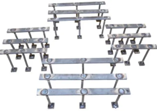
Specimen C-SSR3 had three rows of shear reinforcement (Figure 1). In order to facilitate the production, there were only two types of rails in this specimen. The top connecting element was directly supported on the top longitudinal bars in the North-South direction, which in turn were above the East – West top bars. A photo of the complete set of shear studs for specimen C-SSR3 is given in Figure 2.
Figure 2 Photo of the complete set of studs for specimen C-SSR3
The other specimen (C-SSR5a) had similar details but for five layers of shear reinforcement. Again, there were only two types of rails in this specimen. A plan view of the shear reinforcement for both specimens is given in Figure 1 along with the Eurocode 2 [11] outer punching perimeter uout,ef. The length of the outer perimeter is uout,ef =3211mm. Due to
the restrictions imposed on Eurocode 2 critical perimeter for the cruciform layout of shear reinforcement, the exact same value of uout,ef applies to both specimens.
2.4 Test setup and loading protocol
Common test setups used in the past for lateral cyclic loading of flat slab-column connections usually employ specimens with dimensions equal to the region of the slab under negative bending moments. They usually employ pinned or movable supports for the slab and pinned support for the column. Lateral cyclic loading is usually applied at column ends (or at one column end) or at slab ends. Such test setups have been commonly accepted and used as good and simple representatives of slab-column connections. However, they use simplified boundary conditions, such as borders that are bending moment free and vertically fixed, which lead to a static position of the zero moment line, the inability to have bending moment redistribution and supported borders that can absorb vertical load. In order to overcome some of these limitations a different test setup has been developed at Department of Civil Engineering, Faculty of Science and Technology, Universidade NOVA de Lisboa (DEC/FCT/UNL). An idealized schematic representation of the test setup is shown in Figure 3-a. This setup allows vertical displacements at the opposite slab borders; equal magnitude shear forces, bending moments and rotations at the slab edges; mobility of the line of inflection location along the longitudinal direction and high vertical load ratios.
The vertical load is applied through steel plates to the top slab surface in eight points to better approximate a uniformly distributed load, and is intended to be constant throughout the whole test. This is accomplished by using a system of steel elements that follow the slab horizontal deformations without exterior conflicts. The load is applied using four hydraulic jacks connected to a Load Maintainer machine. A photograph of the setup is shown in Figure 3-b. A more detailed description of this test setup is included in Almeida et al [10].
After reaching the target value, the vertical load is kept constant during the rest of the test. The total vertical load at the critical perimeter was 196.35 kN for specimen C-SSR3 and 169.21 kN for C-SSR5a. These loads correspond to approximately 55% of the concentric punching shear resistance of each specimen (without the contribution of shear reinforcement), calculated based on Eurocode 2 [11] with average values for material characteristics.
After the application of the gravity load, lateral cyclic displacements were applied at the top end of the column, as described in Figure 4. The height of the column is 2000mm, therefore the lateral drift ratios are obtained by dividing the horizontal displacement by the column height (values for drift ratio are plotted in the right Y-axis in Figure 4).
Figure 4 Lateral displacements history
For drift ratios smaller than 4%, the cycles for each target drift are repeated three times, in order to observe the strength and stiffness degradation during successive cycles. Two repetitions are performed for 4% drift ratio. For higher drifts, only one cycle per target drift is completed. Target drifts are increased in steps of 0.5% until failure of the specimen.
2.5 Instrumentation
Strain gauges were installed in 15 studs of specimen C-SSR3 and in 25 studs of the specimen C-SSR5a, as indicated in Figure 1. Four rebars of the top reinforcement were equipped with strain gauges in two symmetric locations near the column. Strain gauges were installed in two bottom rebars at locations near the column and at the positive bending moment region. Fourteen deflectometers were installed along the longitudinal axis of the slab and four deflectometers were installed in the perpendicular direction to monitor deflections of the slab, in similarity with the tests of Almeida et al [10].
-140 -120 -100 -80 -60 -40 -20 0 20 40 60 80 100 120 140 -7.0% -6.0% -5.0% -4.0% -3.0% -2.0% -1.0% 0.0% 1.0% 2.0% 3.0% 4.0% 5.0% 6.0% 7.0% dr ift rat io [% ] horiz ont al dis plac em ent [m m ] time
3 EXPERIMENTAL RESULTS 3.1 Load-deformation response
The hysteretic diagrams showing the horizontal force – displacement (unbalanced moment – drift ratio) relationships are given in Figure 5 and Figure 6 for specimen C-SSR3 and C-SSR5a respectively.
Figure 5 Hysteretic diagram for specimen C-SSR3
-140-120-100 -80 -60 -40 -20 0 20 40 60 80 100 120 140 -80 -60 -40 -20 0 20 40 60 80-7 -6 -5 -4 -3 -2 -1 0 1 2 3 4 5 6 7 -160 -120 -80 -40 0 40 80 120 160 Drift (%) U nbala nc ed m om ent (k N m ) H oriz ont al fo rc e (k N ) Horizontal displacement (mm) -140-120-100 -80 -60 -40 -20 0 20 40 60 80 100 120 140 -80 -60 -40 -20 0 20 40 60 80-7 -6 -5 -4 -3 -2 -1 0 1 2 3 4 5 6 7 -160 -120 -80 -40 0 40 80 120 160 Drift (%) U nbala nc ed m om ent (k N m ) H oriz ont al fo rc e (k N ) Horizontal displacement (mm)
The other specimen (C-SSR5a) attained a maximum horizontal force of 54.5kN (unbalanced moment 109.0kNm) and gradually lost it with each cycle until the test was stopped at 6.0% due to limitations of the test setup. At the final cycle, the horizontal force dropped at 44.5kN (unbalanced moment 89.0kNm), which is about 82% of the maximum attained force and unbalanced moment.
3.2 Strains in the reinforcement
Based on the strain gauge readings for both specimens, it was noticed that the studs in the second perimeter of shear reinforcement (measured from the column) experienced the highest strains. Strains in few studs were close to yielding values starting from 3.0% drift ratio. For specimen C-SSR5a, it was noticed that strains in the fifth perimeter of shear reinforcement were very low (close to zero).
4 COMPARISON WITH THE SPECIMEN WITHOUT SHEAR
REINFORCEMENT
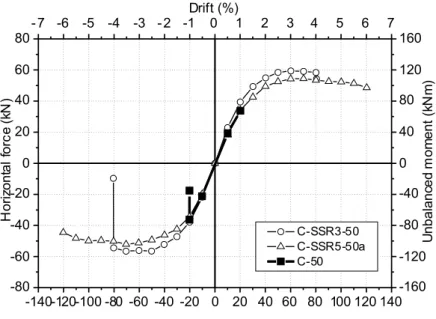
The specimen without shear reinforcement is named C-50 and it is described in detail in Almeida et al [10]. The material characteristics in specimen C-50 were similar to those of specimen C-SSR3. The Gravity Shear Ratio was approximately 50%. A comparison of the backbone curves for the three specimens is shown in Figure 7.
Figure 7 Comparison of backbone curves
In contrast to the two previously described specimens with shear studs, specimen C-50 failed in a brittle manner before reaching the negative bending moment flexural capacity, at a drift ratio of only 1.0%.
5 CONCLUSIONS
The lateral reversed cyclic loading tests of two specimens reinforced with shear studs were presented. A comparison was made with a similar specimen but without shear reinforcement. The comparison showed that the enhancement in strength and deformation capacity for both specimens with shear reinforcement was considerable. It was shown that,
-140-120-100 -80 -60 -40 -20 0 20 40 60 80 100 120 140 -80 -60 -40 -20 0 20 40 60 80-7 -6 -5 -4 -3 -2 -1 0 1 2 3 4 5 6 7 -160 -120 -80 -40 0 40 80 120 160 C-SSR3-50 C-SSR5-50a C-50 Drift (%) U nbala nc ed m om ent (k N m ) H oriz ont al fo rc e (k N ) Horizontal displacement (mm)
even though the outer perimeter uout,ef was the same for both specimens, the specimen with
three rows of studs failed outside the shear reinforced zone, whereas the other specimen had a gradual failure. In both specimens, the flexural capacity of the section close to the column was reached. In contrast, the specimen without shear reinforcement failed in a brittle manner for a drift ratio of only 1.0%. Relatively large strains in the second perimeter of studs for both shear reinforced specimens reveal that diagonal cracks tended to develop through the shear studs but were effectively restricted by them. It should be noted, however, that the two specimens with shear studs had considerably different concrete strengths and further investigation is required in order to derive more general conclusions.
REFERENCES
[1] S. J. Brown and W. Dilger, Seismic Response of Slab Column Connections, Calgary, Alberta, Canada: University of Calgary, 2003.
[2] H. Cao and W. H. Dilger, Seismic Design of Slab-Column Connections (Master of
Science Thesis), Calgary, Alberta, Canada: University of Calgary, 1993.
[3] I. N. Robertson, T. Kawai, J. Lee and B. Enomoto, "Cyclic Testing of Slab-Column Connections with Shear Reinforcement," ACI Structural Journal, vol. 99, no. 5, Sept.-Oct., pp. 605-613, 2002.
[4] Y. Tan and S. Teng, "Interior Slab-Rectangular Column Connections Under Biaxial Lateral Loadings," in SP-232 Punching Shear in Reinforced Concrete Slabs,, Farmington Hills, Michigan, USA, American Concrete Institute, 2005, pp. 147-174.
[5] C. E. Broms, "Flat Plates in Seismic Areas: Comparison of Shear Reinforcement Systems," ACI Structural Journal, vol. 104, no. 6, November-December, pp. 712-721, 2007.
[6] T. H.-K. Kang and J. W. Wallace, "Seismic Performance of Reinforced Concrete Slab-Column Connections with Thin Plate Stirrups," ACI Structural Journal, vol. 105, no. 5, September-October, pp. 617-625, 2008.
[7] J.-K. Song, J. Kim, H.-B. Song and J.-W. Song, "Effective Punching Shear and Moment Capacity of Flat Plate-Column Connection with Shear Reinforcements for Lateral Loading," International Journal of Concrete Structures and Materials, vol. 6, no. 1, pp. 19-29, 2012.
[8] E. M. Matzke, R. D. Lequesne, G. J. Parra-Montesinos and C. K. Shield, "Behavior of Biaxially Loaded Slab-Column Connections with Shear Studs," ACI Structural Journal, vol. 112, no. 3, May-June, pp. 335-346, 2015.
[9] H.-G. Park, Y.-N. Kim, J.-G. Song and S.-M. Kang, "Lattice Shear Reinforcement for Enhancement of Slab-Column Connections," Journal of Structural Engineering ASCE, vol. 138, no. 3, March, pp. 425-437, 2012.