Abstract
An experimental procedure is carried out to investigate response features of semi-deep reinforced concrete (RC) beams with domi-nant static shear failure subjected to low-velocity impact dynamic load both in intact and retrofitted cases. Built specimens have scaled geometry and material properties preserving physical simi-larity with full-scale members and are strengthened using external-ly bonded carbon fiber reinforced poexternal-lymer (CFRP) sheets. Con-ducted tests gather reliable and robust data revealing notable stiffness and strength recovery within skin attachment. Desired performance criterion is detected here as concrete flexural cracking along span only when brittle shear collapse is prevented. Peak absorbed impulse capacity is attained for unidirectional carbon fiber retrofit. Stiffness is recovered initially during first impacts and then starts degrading due to rupture of horizontal fibers in cross-ply retrofit, but provided stiffness is stable for unidirectional retrofit during all impacts.
Keywords
Reinforced Concrete Beam, Shear Failure, Low-Velocity Impact, CFRP Retrofit, Damage Assessment.
Effects of CFRP Retrofit on Impact Response
of Shear-Deficient Scaled Reinforced Concrete Beams
1 INTRODUCTION
Reinforced concrete structures with transportation, offshore and naval applications endure impul-sive transient loads frequently during their service life. Stability and functionality of such members subjected to high-rate dynamic forces depends on the strength and resilience of components. The brittle fracture of concrete, strictly depends on strain rate and increases the response fragility for impulsive loadings. Severe concrete block punching causes global stability loss without exploit of potential material strength and ductility. Dissimilar to flexural failure, discontinuities arise in con-crete volume due to steel stirrups rupture and degrade energy absorption as a consequence in shear collapse mode.
Erfan Shafei a
Mohammad Zaman Kabir b
a Ph.D. Student, Structural Engineering,
Department of Civil and Environmental Engineering,
Amirkabir University of Technology, Teh-ran, Iran.
b Professor, Structural Engineering,
Department of Civil and Environmental Engineering,Amirkabir University of Tech-nology, Tehran, Iran.
http://dx.doi.org/10.1590/1679-78251290
Latin American Journal of Solids and Structures 12 (2015) 60-76 Khalifa and Nanni (2000) investigated the strength and ductility improvements in carbon fiber reinforced polymer (CFRP) retrofitted T-section RC beams. The studies conducted by Al-Mahaidi et al. (2001), Zhang and Hsu (2005) are related to the static shear strength and ductility assessment of strengthening RC members with initial shear damages. The impact behavior of beams with dom-inant shear failure was target of Zineddin and Krauthammer (2007) experiments. Later Saatci and Vecchio (2009) investigated the formation process of punching shear cracks and their sensitivity to shear strength of the section. Bhatti et al. (2009) also studied the response features of intact RC beams and detected catastrophic shear failures for beams with various shear-to-flexure strength ratios. Therefore, an intensive study is necessary on retrofitting techniques of impact-induced shear failure. Further wide data are essential in order to declare response feature of both intact and retro-fitted members.
Current studies investigates the dynamic response features of intact and CFRP wrapped simply supported RC beams with initial shear strength deficiencies subjected to drop-weight impacts with an experimental approach. External-bond sheets are to restrain severe velocity gradients and miti-gate damages in concrete. The provided extra stiffness is to improve the frequency content of dy-namic response in the form of a stable oscillation domain during impact recurrences. Lay-up type effects on stiffness recovery and the peak strain of the load-resisting elements are the main target. Peak strain values in adhering CFRP sheet mainly govern subsequent failures in concrete and em-bedded steel.
Recorded time histories consist of mid-span deflection, over-span accelerations, and strains of all material components. Dynamic records also monitor and evaluate the strain components next to the probable failure zone for all samples. Observations aim local failures in concrete, CFRP, and steel, which discuss collapse modes of intact and strengthened members in detail. The fast Fourier trans-formation (FFT) method extracts the vibration frequency content and demonstrates variations in the form of spectrum amplitude (FSA) diagrams. The changes of dominant modes with respect to elastic case quantifies the damage mitigation capability of each retrofit scheme. Spectrum amplitude change in retrofitted beams with respect to damaged intact case additionally quantifies strengthen-ing effect of CFRP. Peak material strains, deflection and impulse also provide scalar data definstrengthen-ing shear damage measures in impact tests.
2 EXPERIMENTAL OUTLINE 2.1 Structural Strength Scaling
Although full-scale members are targets of retrofit procedures, model samples are practical to cast and test in laboratory site due to apparatus and fixture limitations. Keeping constant the dimen-sionless sets of primary variables satisfies physical similarity of scaled and original size continua
Latin American Journal of Solids and Structures 12 (2015) 60-76
concrete beam leads to Equation 1 with some terms defined in the form of crushing strength (
f
́c) as Equations 2 along with CEB-FIP (1990) suggests.P
d .5√E Gf= φ
f́ d .5 √E Gf,
fyd .5 √E Gf ,
vfyvd .5 √E Gf ;
E
d .5√E Gf → P̂ = φ (N , N , NV; ̂) (1)
E = f́ .5, f́ = . f́ .5, G
f= . f́ − (2)
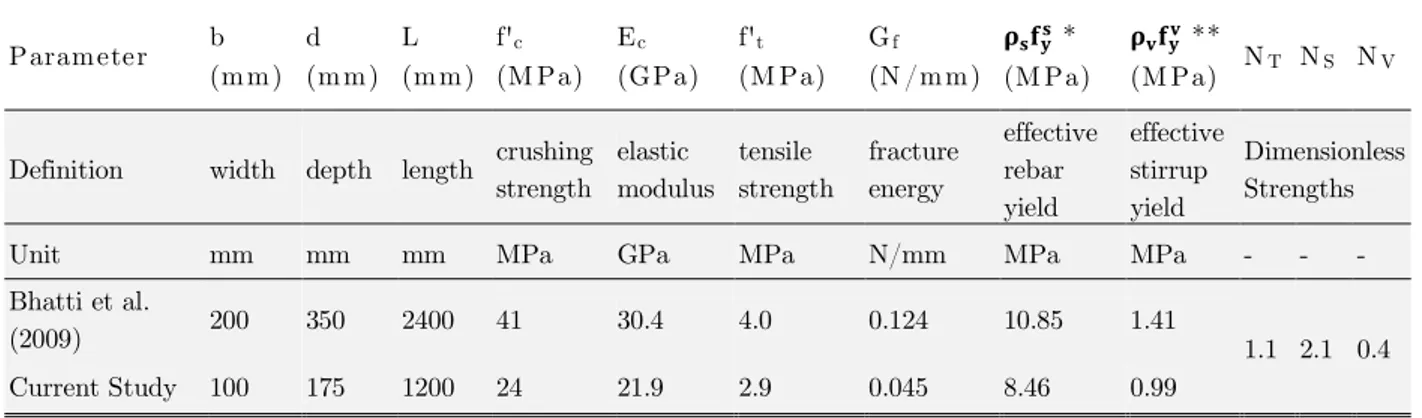
The terms NT, NS, and NV are dimensionless strengths of tensile concrete, flexural rebar, and shear stirrup respectively. Load and deflection marked with hat sign identify their dimensionless form. Beam depth (d) is the only independent variable in current study while the length (L) and width (b) are proportional to depth due to the geometric similarity. The physical similarity exists only if the dimensionless strengths are constant among full-scale and small-scale RC beams.
Parameter b (m m) d (m m) L (m m) f'c (M Pa) Ec (GPa) f't (M Pa) Gf
(N /m m) ����� * (M Pa)
����� **
(M Pa) NT NS NV
Definition width depth length crushing strength elastic modulus tensile strength fracture energy effective rebar yield effective stirrup yield Dimensionless Strengths
Unit mm mm mm MPa GPa MPa N/mm MPa MPa - - -
Bhatti et al.
(2009) 200 350 2400 41 30.4 4.0 0.124 10.85 1.41 1.1 2.1 0.4
Current Study 100 175 1200 24 21.9 2.9 0.045 8.46 0.99
* = total rebar area width × depth⁄ ** v= total stirrup area width × stirrup spacing⁄
Table 1: Full-scale and small-scale properties and dimensionless mechanical parameters
Target test samples in the current study are considered ½ scales of shear-deficient RC beams tested by Bhatti et al. (2009), which showed 41 MPa crushing strength with 2.5 shear span-to-depth (L/2h) ratio, and 20 mm maximum aggregate size. Therefore, iterative calculations demonstrate that a concrete mixture with 24 MPa crushing strength and 10 mm maximum aggregate size is appropriate for scaled beams in order to provide 1.1NT, dimensionless strength, as calculated in Bhatti et al. (2009)tests. The details of material and geometry variables are in Table 1, which is the basis for specimen preparation.
2.2 Specimen Preparation and CFRP Retrofit
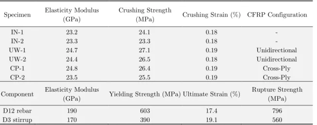
Latin American Journal of Solids and Structures 12 (2015) 60-76 are water-cured with 21 days in 17 °C warmth. Capped concrete cylinders are compressed quasi-statically to crush with strain rate of 2×10⁻⁵ (Sec-1) in 28-day age, which average modulus, strength, and related strain are acquired as 20.2 GPa, 25.5 MPa, and 0.25% in order.
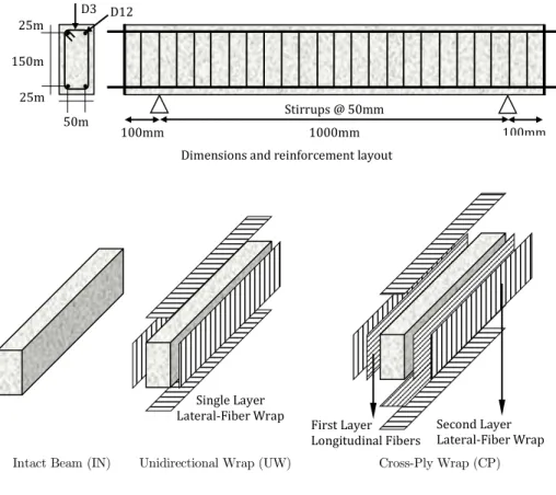
Two D12 bars with 603MPa yield stress in each bending side at 25 mm concrete cover and D3 wire ties with 390 MPa yield stress with 50 mm spacing are flexural and shear reinforcements re-spectively in order to provide 2.1 and 0.4 for NS and NV dimensionless strengths. Longitudinal rebar anchors to ends mechanically using 8 mm thick plates. Beam specimens have identical material and reinforcement layouts, but different CFRP retrofit outlines. Beams without any retrofits are intact and have IN letters in name for demonstration. However, beams with unidirectional and cross-ply CFRP wraps are retrofitted and have UW and CP name letters respectively. Target is to investi-gate the fiber alignment effect on dynamic response. Figure 1 shows the details and layout of all specimens and Table 2 summarizes the concrete and steel material properties.
Dimensions and reinforcement layout
Intact Beam (IN) Unidirectional Wrap (UW) Cross-Ply Wrap (CP)
Figure 1: Reinforcement and CFRP wrapping scheme configurations of specimens.
100mm 1000mm 100mm
25m m
D3 D12
25m m 150m
m
50m m
Stirrups @ 50mm
Single Layer Lateral-Fiber Wrap
First Layer Longitudinal Fibers
Latin American Journal of Solids and Structures 12 (2015) 60-76 Specimen Elasticity Modulus
(GPa)
Crushing Strength
(MPa) Crushing Strain (%) CFRP Configuration
IN-1 23.2 24.1 0.18 -
IN-2 23.3 23.3 0.18 -
UW-1 24.7 27.1 0.19 Unidirectional
UW-2 24.4 26.5 0.18 Unidirectional
CP-1 24.8 26.4 0.19 Cross-Ply
CP-2 23.5 25.5 0.19 Cross-Ply
Component Elasticity Modulus
(GPa) Yielding Strength (MPa) Ultimate Strain (%)
Rupture Strength (MPa)
D12 rebar 190 603 17.4 796
D3 stirrup 170 390 19.1 560
Table 2: Material Property Test Results of RC Specimens.
Two specimens are intact control prototypes (IN) without any retrofitting, but carbon fiber sheets with 0.17 mm thickness (tf) wraps four specimens with unidirectional and cross-ply stacking. Speci-mens with UW letters have three 700×500 mm sheet wraps in length and vertical fibers (90°). Se-ries with CP identification have an initial 1200×500 mm sheet with horizontal fibers bonded to webs and bottom face that form a cross-ply (0°/90°) stacking with three vertical-fiber 700×500 mm sheets. The overlap length is 50 mm according to ACI 440.2 (2008) guides. The Figure 2 demon-strates the process of manufacture and strengthening of test samples.
The mechanical properties of the selected CFRP material are introduced as 1764 kg/m3 density ( f), 230 GPa elastic modulus (Ef), 3450 MPa tensile strength (ft), 2690 MPa compressive strength (fc), 1.5% ultimate strain ( u) a“d 0.33 P”iss”“’s rati” (νf) properties. The epoxy resin has 17.2 GPa elastic modulus (Em), 55 MPa tensile strength (fm) a“d 0.45 P”iss”“’s ratio (νm) with optimum 1.0 mm thickness required for each CFRP sheet wrap as recommended by Zhang and Hsu (2005). Al-terations in impact response of repairing members during transient and steady state phases are main investigation targets with respect to intact shear-deficient case. Additional horizontal fibers in a cross-ply scheme is to enhance both shear and flexural stiffness simultaneously and control the strain field near failure zone.
Concrete de-molding CFRP sheet bonding CFRP sheet wrapping Curing of CFRP retrofits
Latin American Journal of Solids and Structures 12 (2015) 60-76 2.3 Impact Load Identification
Weight and height of drop are determined generally considering the equilibrium of applied kinetic energy and external work required to generate a total collapse of the structure (either shear or flex-ural), which results in an impact force much higher than static capacity. Equations 3 and Equation 4 determines the nominal flexural and shear capacities of an intact specimen according to ACI 318-08 (20318-08) respectively as below.
Mn= . f́ β cb (d −β c) , c = . f́ βfyd , β = . − . f́ → . ≤ β ≤ . (3)
Vn= . √f́ + vfyv bd (4)
Based on material properties of specimens, the nominal moment (Mn) and shear strength (Vn) of beam section are 20.84 kN.m and 34.32 kN, respectively. Therefore, the mid-span static point load for flexural and shear collapse is evaluated as 78.3 kN and 69.8 kN, correspondingly.
The static internal energy of intact beam collapse is the basis for weight and velocity determina-tion of the projectile. Static monotonic test reveals an ultimate load capacity as 70.1 kN and failure deflection 11.2 mm as with an internal energy absorption equal to 392.3 kN×mm. The 1.0-meter drop height selected by Bhatti et al. (2009) in full-scale tests is also valid in the current study with 4.3 m/sec collision velocity (Vd) in order to maintain the low-velocity conditions. Thus, the projec-tile mass (m ) is taken to be 40 kg to provide the required kinetic energy. The elastic ideal impact force is V�√K m according to Jones (1997). Bending-shear stiffness of test beam (K ) is given by
Equation 5. If the structure is assumed to behave elastically, the applied impact dynamic force will be 229.5 kN that is much higher than its static capacity.
K =L + . d LE bd (5)
2.4 Outline of Test Setup and Instrumentation
Latin American Journal of Solids and Structures 12 (2015) 60-76
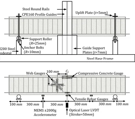
Figure 3: Set-up and instrumentation used for drop-weight impact test.
Figure 4 demonstrates the provided experimental setup for drop-weight impact tests. Output cables of all sensors connect to external bridges of 10-channel wideband digital dynamic data logger with a 20 kHz sampling rate. Primary response records consist of mid-span deflection, over-span location
accelerati”“s, a“d c”mp”“e“t strai“i“g time hist”ries. Acc”rdi“g t” Nyquist’s (1928) sampling theo-rem, digitizing rate should at least be twice the highest frequency covered in record signal to avoid aliasing. Thus, signals with frequencies lower than 10 kHz capture accurately in current study. De-flection and acceleration signals are to have frequency contents lower than 5.7 kHz, which covers 93% of modal mass participation according to elastic vibration eigenvalue analysis. Acquired oscilla-tion frequencies are upper bonds of inelastic transient response due to material nonlinearity and fracture mechanisms. Thus, logging rate is quite enough to capture continuous response of the structure and satisfies the required accuracy.
Figure 4: Provided drop-weight test setup, dynamic data logging, and imaging systems.
300 mm 300 mm
100 mm
100 mm CL
Web Gauges Compressive Concrete Gauge
Tensile Rebar Gauges
300 mm 300 mm
Optical Laser LVDT
(Stroke=50mm)
MEMS ±2000g Accelerometer
100 mm
Support Roller (R=25mm) H200 Steel
Pedestal
Anchor Bolts
(R=10mm)
Uplift Plate (t=5mm)
Steel Base Frame Guide Support
Plates (t=7mm)
CPE160 Profile Guides Steel Round Rails
Latin American Journal of Solids and Structures 12 (2015) 60-76
3 EXPERIMENT RESULTS 3.1 Time History Records
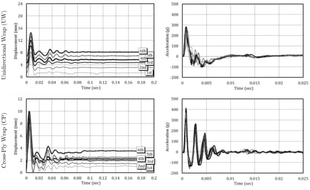
Mid-span deflection and acceleration histories of beams are present in Figure 5. There is no record-able data for intact samples (IN) after fourth impact due to excessive damage such as deep shear cracks and thoroughly scabbed concrete block. The oscillation ability of intact beam suddenly fails after the first impact. Peak and residual deflections at fourth impact are 25.1 mm and 23.2 mm where the relative difference is small without any meaningful recovery. Response time increases intensively from 5.6 milliseconds up to 19.6 millisecond, as impacts are repeated. Mid-span accelera-tion is 155.4 g at first impact and drops to 41.9 g at fourth impact. The dramatic difference be-tween first response and last response indicate concrete damages.
Unidirectional-wrapped beams (UW) endure several impacts with stable plastic deflection. They resist six impacts by flexural plastic hinge at the mid - span location without losing stability. Re-strained deflections have a peak and residual values as 14.5 mm and 8.2 mm in final impacts with sensible recovery. Considering fourth impact, the maximum and residual deflections decrease by 50% and 76% respectively in comparing to intact case. The peak deflection time is 8.1 milliseconds for all impacts and the vibration damps totally by 0.1 sec period. Resisted acceleration at mid-span point is 177.1 g for first impact, increases up to 269.1 g regarding third repeat, and remains almost same for the rest load repeats. The increase and stabilization in acceleration intensity here is a func-tion of gradual stress transfer from concrete to CFRP and steady confined concrete crushing. Cross-ply (CP) CFRP improves the response to significant stiffness restoration. Peak and resid-ual deflections are 9.8 mm and 3.5 mm, respectively, for sixth impact with 32% and 43% reduction with respect to UW beams. Residual deflection remains almost the same during five load repeats and slightly increases in sixth repeat due to rupture of longitudinal CFRP fibres. Peak deflection occurs in 5.6 milliseconds and the vibration continues up to 120 milliseconds. Mid-span acceleration is 193.4 g for first impact, then increases up to 422.8 g at third repeat and finally decreases to 318.3 g. The decay in peak acceleration is due to rupture of horizontal fibres in bottom surface.
In
ta
ct
(
IN
Latin American Journal of Solids and Structures 12 (2015) 60-76
U
ni
di
re
ct
io
na
l
W
ra
p
(U
W
)
C
ro
ss
-P
ly
W
ra
p
(C
P
)
Figure 5: Mid-span deflection and acceleration time histories.
3.2 Detected Failure Remarks
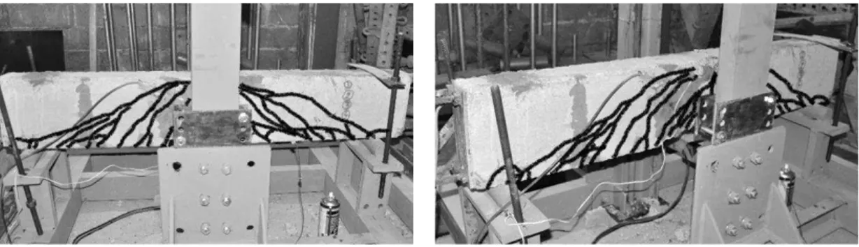
The visible cracking of specimens are marked after each impact drop as shown in Figure 6. Several vertical cracks form in concrete free cover of intact beams (IN) and two 45°-incline shear cracks were developed in ¼ and ¾ of span initially. Diagonal cracks adjacent to supports appear by second impact and develop toward major shear cracks. The third impact deepens, extends, and congregates shear cracks over shear-span and orients them toward steel rebar level causing loss of concrete-rebar bond strength and increasing shear damage. Last impact results in 0.8 mm opening of major shear cracks, scabbing of tension look and a detachment of compressive concrete. The inclined near-support cracks develop suddenly and propagate toward collision point. The crack pattern damages whole the span-length beam web and therefore failure classifies into a shear mode that ruins poten-tial structural capacity.
Samples with unidirectional wraps (UW) have flexural cracks in a resin matrix parallel to carbon fibres initially, which propagate toward mid-height of the web. Then CFRP fibres separate along opened resin cracks at 2h-length in mid-span location during second impact. The third impact re-tains penetration of drop weight and increase of vertical crack depth. The fourth and fifth impacts result in volumetric expansion of confined concrete, inclination and distribution of flexural cracks over ¼ and ¾ of span length. Finally, the swelling of confined concrete in 50×100 mm block size and CFRP rupture along crack inclinations reveal within sixth impact repeat.
Latin American Journal of Solids and Structures 12 (2015) 60-76 third impacts. The fourth impact causes minor swelling of compressive concrete and redistribution of flexural cracks along the beam height. Finally, partial rupture of CFRP fibers along inclined shear deformation path, crushing of concrete confined beneath composite and total rupture of hori-zontal CFRP fibers in bottom face are apparent for fifth and sixth impacts respectively. Detach-ment between CFRP and concrete surface is not effectively governing in current tests, as the wrap-ping is thorough along samples for both UW and CP retrofits. There is no free edge is CFRP-concrete interface and the overlap length is quite sufficient to prevent the interface disengagement. If there is any detachment between CFRP and concrete surface, retrofit confines concrete and beam resists impact without losing strength and stiffness.
(a) Deep opening along shear cracks and tensile concrete scabbing is dominant in IN beams
(b) Vertical cracks and confined concrete occur in UW retrofitted beams
(c) Shear-flexural resin cracking and CFRP rupture raise in CP retrofitted beams
Latin American Journal of Solids and Structures 12 (2015) 60-76
4 DYNAMIC DAMAGE ASSESSMENT 4.1 Material Strain Peaks
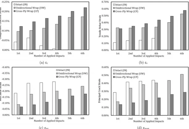
Material components providing stiffness and strength of reinforced concrete members subjected to impulsive loadings shall be operational during transient and steady state responses without losing stability, but mitigating imposed damages. CFRP material is to restrain damage and rearrange load-carrying mechanisms. In order to measure the damage-mitigating efficiency of retrofit, peaks of compressive concrete strain (εc), tensile rebar strain (εs), web shear strain (εxy) and principal crack strain (εmax) measured using foil gauges. Records are present in all beams and materials.
Compressive Concrete Strain (εc)
Horizontal gauge attached on top mid-span side face next to impact point measuring compression is used for evaluation of concrete compressing capacity and recorded peak values are stated in Figure 7-(a). Axial quasi-static crushing test of unconfined concrete cylinders reveals peak and ultimate strains as 0.19% and 0.45% respectively. However the intact samples were only little straining up to 0.06% in second load repeat and then loses its stability in the form of a sudden drop off by earlier shear failure. Unidirectional CFRP wrapping scheme provides uniform strain rising with value sta-bilization toward 0.17% for laterally confined concrete with higher ductility. Cross-ply course makes straining raise regime of concrete linear because of horizontal CFRP fibers up to 0.22% level where material starts to crush plastically. Thus employing composite skin improves ductility level of com-pressive concrete especially when additional flexural stiffness is present.
(a) εc (b) εs
(c) εxy (d) εmax
Latin American Journal of Solids and Structures 12 (2015) 60-76
Tensile Steel Rebar Strain (εs)
Embedded foil gauges attached to bottom rebar face in mid-span location also record extension of steel material and provide records as Figure 7-(b). Average yield strain is 0.32% regarding monoton-ic tensile test results for D12 mild steel. Catastrophmonoton-ic shear failure occurred in intact samples pre-vents rebar plasticity with only 0.21% tensile strain in 4th load repeat waiving ductile flexure mech-anism. Providing vertical fracture-restraining CFRP material initiates stable yielding toward fourth impact and then intensifies to 0.53% at ending. This observation is equivalent to completion of plastic flexural hinge in mid-span as marked with crack widening and concrete confinement previ-ously. Although horizontal carbon fibers provide additional flexural restrains in cross-ply CFRP scheme, steel yielding has a stronger and uniform growth versus load repeats up to 0.58% strain level. Here the enhanced ductility of CP samples is due to parallel increase of steel and concrete straining which recommends current retrofit scheme than a unidirectional fiber case.
Web Shear Strain (εxy)
Although major shear cracks generate farther than a gauging point, recorded shear strain in Figure 7-(c) has a value of 0.28% much higher than shear fracture strain, 0.01%. Localization of shear cracks has very high rate leading to deterioration of load carrying paths of concrete block under direct shear and results in steel stirrup rupture. Supplementation of vertically orientated CFRP sheets in UW specimens significantly reduces web shear strain, especially during first impact re-sponse. The shear straining regime is stable for rest impact repeats and final value is 0.24% tolerat-ed by carbon fibers and internal steel stirrups. Cross-ply retrofit stabilizes shear strain increase and minimizes distortion of the web for all impact repeats. The ultimate reached shear strain recorded as 0.18% with a distributed shape over shear-span of CP strengthened samples. As a general idea, cross-ply CFRP sheet implementation reduces shear deformation of specimens using a homogenous shear stiffness provided for web directly than unidirectional CFRP sheet wrap only if shear restrain-ing is preferred as performance target.
Principal Crack Strain (εmax)
Intact samples exhibit sudden damage response based on the hysterical increase of the principal strain in Figure 7-(d) up to 0.44%, beyond 0.02% fracture strain) as shown in figure. The similar variation regime of tensile and shear strains proves the domination of the shear fracture on exces-sive cracking of concrete volume. However, when vertical CFRP fibre is present in UW specimens, crack strain diminishes significantly for first impact and then rises up to 0.51% of the rest impacts. The shear-cracking pattern changes into flexural mode with span-over distribution. However, cross-ply retrofit restrains flexural cracking and reduces ultimate crack strain to 0.29%. Generally the unidirectional CFRP pattern is strongly preferred than cross-ply case if the ductility enhancement is the performance criterion.
4.2 Frequency Content Spectrum
The frequency content of beam vibration can evaluate the damage mitigation capability of retrofits. Frequency values (ω) are independent variables and the spectrum amplitudes (Aω) calculate as
Latin American Journal of Solids and Structures 12 (2015) 60-76
theoretically has use of post-damage assessment according to Chang and Liu (2003) literature, eval-uation of dynamic fracture and the affectivity of CFRP retrofit reveal well with this method.
Aω =
√ ∫ f t e−iω dt (6)
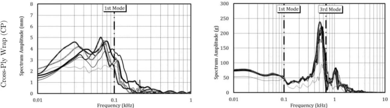
The period selected for frequency decomposition is 0.2 sec when the kinetic energy of the beam is ignorable. Content deviation from the elastic oscillation frequency depicts the damaging rate within whole components. For simplification of analysis, peak spectrum amplitude monitors the stiffness degradation of beams. Extracted data are presented in Figure 8 and represent Aω spectrum ampli-tude versus ω vibrati”“ freque“cy. The 102.1 Hz and 677.4 Hz vertical dashed lines stand for fre-quencies of first and third elastic vibration mode.
Intact samples have peak deflection amplitudes in 47.7, 26.5, 15.9, and 10.6 Hz regarding impact repeats, which are severely far from the first mode elastic limit due to high-intensity shear damage. Stiffness quantification here is function of the quadratic ratio of nonlinear-to-linear deflection oscil-lation frequencies as a global response characteristic of the structure. The effective residual stiffness is 23%, 7%, 3% and 1% of initial status assuming the consistency of the mass. Recorded acceleration has also a peak at 78, 58, 39, and 19 Hz frequencies while the third mode heap is active apparently in the spectrum. Shear fracture causes continuum discontinuities and lead to overall rigidity loss. Stiffness of shear-deficient samples lacks in recovery and gives rise to higher deflection time and resisting acceleration potential. In addition, frequency content below stated points has levelheaded amplitudes showing the strong probability of further strength degradation along next impact re-peats.
Deflection Acceleration
In
ta
ct
(
IN
)
U
ni
di
re
ct
io
na
l
W
ra
p
(U
W
Latin American Journal of Solids and Structures 12 (2015) 60-76
C
ro
ss
-P
ly
W
ra
p
(C
P
)
Figure 8: Deflection and acceleration frequency content spectrum of testing specimens.
Strengthened members with unidirectional CFRP wraps exhibit unique spectrum characteristics as a strong reduction in amplitudes and frequency deviation. Extracted curves have peaks at 74.3 Hz for first 3 impacts, 68.9, 63.6, and 58.4 Hz for rest successive repeats regarding 55%, 48%, 41%, and 38% conservation of initial stiffness consequently. Curves almost cover a frequency band with 50-Hz length showing off shear strength improvement in comparing to intact case. Damaging rate is stable for first impacts along acquired frequencies, but then starts to increase within concrete failure, rebar plasticity, and vertical CFRP fibre split as loading repeats. Another remarkable notice is on accel-eration spectrum where almost all curves have close peaks at 97.6 Hz for first two loadings and 78.1 Hz for next four repeats. Activation of third vibration mode is much clearer here, but does not have the noteworthy amplitude as first mode. Capability of flexural response in deflection and stiffness recovery of specimens depicts as stabilized frequency content, stabilized damage level, and inaugu-ration of higher vibinaugu-ration modes inside the response. The hysterical degrading regime of intact sam-ples converts into uniform outline while unidirectional CFRP retrofit scheme is used.
Cross-ply CFRP orientation mostly change the observed pattern of spectrum in the form of peak-sharpening and dominant mode shifting. Peak amplitudes of first up to fourth impact curves have the same 79.6 Hz frequency and then occur at 74.3 and 68.9 Hz for fifth and sixth impact re-peats respectively. Here the effective stiffness is 65%, 55% in that order supplied with a 70-Hz broad curve spread domain. Flexural-shear strengthening technique engages higher modal stiffness terms and maintain up to fifth impact as gradual fibre ruptures occur in horizontal CFRP fibres. Acceler-ation spectrum owns a sharp heap passing through 102.1 Hz first mode limit and has an adjacent smooth heap beyond 677.4 Hz third mode limit. Shear deformation effect is stronger in higher vi-bration modes due to curvature variation and caused by cross-ply CFRP skin stiffness. Peak ampli-tudes occur for 605.5, 585.9, 566.4, 546.8, 527.3, and 507.8 Hz for following impacts which show incremental degradation in high-mode stiffness due to fracture of horizontal CFRP fibres. Spectrum pattern of UW case changes in double-heap curves in CP case with 15% relative stiffness alteration.
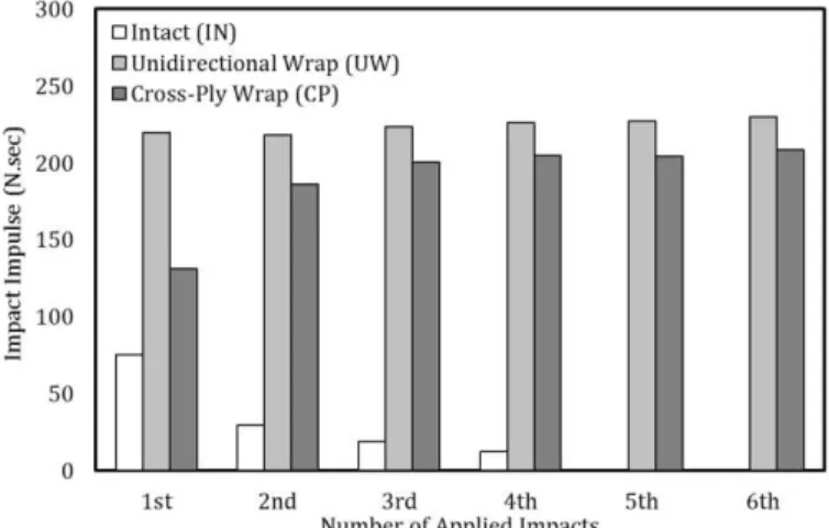
4.3 Absorbed Impulse
Latin American Journal of Solids and Structures 12 (2015) 60-76
to Jones (1997), which is 354.3 N×sec, but the nonlinearity of response results in lower values than above. In addition, main assumption here is the piecewise linear distribution of accelerations over the beam span. This causes approximations in I t Impulse calculation due to local discontinuities that occur in shear failure. Specimen accelerations in three span stations (� , � , �) are the inputs of Equation 7 as below that enable the impulse calculation.
I t = ∫ ∫ Adu̇dxL = ∫ AL A + A + A dt (7)
The calculated values are present in Figure 8 for intact, unidirectional wrap retrofits, and cross-ply wrap retrofits. Intact specimens reveal damaging feature in the form of 75.4, 29.3, 18.6, and 12.2 N×sec straight impulse drop pattern (resisting only 21% of elastic value) while the rigid body mo-tion mechanism is generated over shear fractured stiffness-lacking concrete beam blocks.
Unidirec-ti”“al CFRP wrap scheme stabilizes specime“s’ capacity t” 223.9 N×sec f”r all l”ad repeats, provid-ing 64% elastic impulse level. Governprovid-ing mechanism in this case is flexural crackprovid-ing rather than rebar yielding whereas concrete dissipates collision energy. The desired impact performance of such specimens is constant impulse bearing within restrained shear fracture and uniform flexural defor-mation.
Cross-ply CFRP retrofitting holds 131.6 and 185.9 N×sec impulse level for first two impacts and continue 204.5 N×sec for rest load repeats forming 58% of elastic impulse. Gradual increase of rec-orded impulse is relevant to the undamaged status of horizontal CFRP fibres, which retains re-sponse in almost elastic form. Then, incremental rupture of carbon fibre speeds up flexural cracking and activates rebar-yielding phenomena that results in an increase of absorbed impulse after second impact. It is apparent that plasticity and flexural cracking mechanisms act in an impulse absorption enhancing way by means of improved ductility, but the shear fracture acts in reverse order and reduces impulse absorption. Thus, the strengthening used for shear-deficient concrete members sub-jected to impulsive loads shall consider stiffness, strength, and stability restoration titles indeed of enhanced component ductility and distributed strains.
Latin American Journal of Solids and Structures 12 (2015) 60-76
5 CONCLUSIONS
Current studies investigate dynamic response characteristics of small-scale semi-deep simple rectan-gular reinforced concrete beams with initial shear strength deficiency subjected to drop weight low-velocity with an experimental approach. The properties of constructing samples preserve physical similarity with full-scale beams. Sample also have externally bonded carbon fibre reinforced polymer (CFRP) retrofits in unidirectional and cross-ply stacking. Mid-span deflection, three quarter-span accelerations and strains of materials (concrete, steel and CFRP retrofit) all monitor the global and local responses during the impact load phase.
Based on obtaining results, the unidirectional and cross-ply wrapping schemes decrease highest deflection time by 2.4 and 3.5 ratios respectively, restrain intact dominant shear failure and stabilize damage generation over concrete volume by flexural mode activation. Unidirectional and cross-ply schemes have 52% and 61% peak deflection decrease rates beside 74% and 173% resisted accelera-tion improvements in that order. Shear fracture caused severe discontinuities convert into flexural concrete cracking within yielding of steel rebar especially in cross-ply CFRP retrofitting. Effective dynamic stiffness is 2.5 and 4.2 times in intact case for unidirectional and cross-ply retrofits accord-ing in FFT spectrum analysis. Unidirectional and cross-ply retrofits provide 2.9 and 2.7 enhance-ment ratios regarding absorbed impulse. Outcomes extracted from the present study program are as following points:
Catastrophic fracture degrades the effective resisting material potential to withstand imposed impact energy and thus results in excessive deformation, severe concrete discontinuity along span and steel stirrup ruptures. Also compressive concrete and tensile steel rebar lack to reach their crushing and yielding strain limits respectively on preceding shear collapse. However, ret-rofitting procedures stimulate ductile flexural mode by restraining inclined shear cracks (unidi-rectional fibres) or providing extra flexural stiffness (cross-ply fibres).
Distribution length of flexural cracks in unidirectional CFRP wraps (UW) is larger than analo-gous cross-ply CFRP wrapping (CP) and results in less compressive concrete and tensile steel straining values as impact repeats. Affording higher stiffness in a cross-ply wrapping robustly enhances ductility, but conversely localizes failures.
Although cross-ply retrofit has the minimum shear strain values, shear and principal crack strains grow slower in beams with vertical-only fibres (UW) than the beams with cross-ply fi-bres (CP).
Flexural-shear stiffness provided in cross-ply CFRP retrofit result in wider frequency content in deflection spectrum and major mode-shift in acceleration spectrum in comparing to unidirec-tional CFRP retrofit. However, deflection and acceleration spectrums have the same active fre-quency domain for unidirectional CFRP retrofits, which depicts simultaneous stiffness and duc-tility enhancement.
Latin American Journal of Solids and Structures 12 (2015) 60-76
Unidirectional CFRP retrofit results in desired impulse-absorbing performance than cross-ply scheme, according to stable flexural cracking while preventing the shear fracture.
Based on acquiring results, designer decision on even deflection-restraining or impulse-increasing criterion leads to selection of cross-ply or unidirectional CFRP wrapping techniques. However, sta-bilized failure propagation along strengthened samples is preferred in comparison to the case where components are restricted to deform, although demand stiffness and strength is present.
References
ACI 211.1-08, Sta“dard Practice f”r Selecti“g Pr”p”rti”“s f”r N”rmal, Heavyweight, a“d Mass C”“crete , Ameri-can Concrete Institute, Farmington Hills, MI 48331, USA, 2008.
ACI 318-08, Buildi“g C”de Requireme“ts f”r Structural C”“crete a“d C”mme“tary , America“ C”“crete I“stitute, Farmington Hills, MI 48331, USA, 2008.
ACI 440.2R-08, Guide f”r the Desig“ a“d C”“structi”“ ”f Exter“ally B”“ded FRP Systems f”r Stre“gthe“i“g
C”“-crete Structures , America“ C”“C”“-crete I“stitute, Farmington Hills, MI 48331, USA, 2008.
Al-Mahaidi, R., Lee, K., a“d Tapli“, G. (2001) Behavi”r a“d A“alysis ”f RC T-Beams Partially Damaged in Shear
a“d Repaired with CFRP Lami“ates Structures 2001: pp. 1-8.
ASTM E695, Sta“dard Meth”d f”r Measuri“g Relative Resistance of Wall, Floor, and Roof Construction to Impact
L”adi“g , America“ S”ciety f”r Testi“g a“d Materials, Philadelphia, PA 19103, USA, 2009.
Barenblatt GI. Scaling, self-similarity, and intermediate asymptotics, Cambridge University Press; 1996. Bazant, Z.P. and J. Planas, Fracture and Size Effect in Concrete and Other Quasi-Brittle Materials, CRC Press, ISBN 0-8493-8284-X, 1998.
Bhatti, A.Q., Kishi, N., Mikami, H., a“d A“d”, T., Elast”-plastic impact response analysis of shear-failure-type RC
beams with shear rebars , J”ur“al ”f Materials a“d Desig“, 30, 2009, pp. 502–510.
CEB-FIP Model Code 1990, Comité Euro-International du Béton, Thomas Telford House, 1993.
Cha“g, P. C. & Liu, S. C., Rece“t research i“ “”“destructive evaluati”“ ”f civil i“frastructures , J”ur“al ”f
Materi-als in Civil Engineering, ASCE, 15(3), 2003, pp.298–304.
Jones, N., Structural Impact, Cambridge University Press, London, UK, 1997.
Khalifa, A., a“d Na““i, A, Impr”vi“g shear capacity ”f existi“g RC T-secti”“ beams usi“g CFRP c”mp”sites Ce-ment and Concrete Composites Journal, Volume 22, Issue 3, 1 June 2000, pp: 165–174.
Nyquist, H., "Certain topics in telegraph transmission theory", Trans. AIEE, vol. 47, pp. 617–644, Apr. 1928. Selcuk Saatci, S., Vecchi”, F. J., Effects ”f Shear Mecha“isms ”“ Impact Behaviour ”f Rei“f”rced C”“crete Beams. ACI Structural Journal, V. 106, No. 1, January-February 2009.
Zha“g, Z. a“d Hsu, C., Shear Stre“gthe“i“g ”f Rei“f”rced C”“crete Beams Usi“g Carb”“-Fiber-Reinforced Polymer
Lami“ates. ASCE, J”ur“al ”f C”mp”sites f”r C”“structi”“, 9(2), 2005, pp. 158–169.
Zineddin, M., and Krauthammer, T., Dynamic response and behavior of reinforced concrete slabs under impact