Abstract
This paper presents both the analytical and theoretical investiga-tions on ultimate load carrying capacity and behaviour of CFS unlipped channels with their ends fixed and subjected to axial compression. The numerical studies have been carried out in the elastic as well as in the plastic ranges of loading. The slenderness ratio of the channels chosen is 40, 80,100 and 120. Three different web depths [shallow, medium and deep] with five thicknesses have been chosen. In addition to the numerical studies, compari-son with the design strengths predicted by using North American Standards for CFS structures. It is observed that the design strength predicted by the specifications are conservative for axially loaded columns. In the present investigation, an attempt is made to study the ultimate load carrying capacity and the mode of failure. Load versus axial shortening behaviour has been studied for various slenderness ratios for a few specimens.
Keywords
Cold-formed Steel, Buckling, Axial compression, Unlipped channel, Finite element analysis, Codal provisions.
Numerical and Theoretical Studies
on Cold-Formed Steel Unlipped Channels
Subjected to Axial Compression
Abbreviations
ʎ - Slenderness ratio [Leff/rmin]
CFC - Cold-formed channel FEA - Finite element analysis NAS – North American Standards PFEA - Ultimateload from FEA
PNAS - Ultimateload from NAS
Dr. G. Beulah Gnana Ananthi 1* Dr. G.S.Palani 2
Dr. Nagesh.R.Iyer 3
1* Assistant Professor, Department of
Architecture, SAP Campus, Anna University, Chennai - 600025, India Author email: [email protected]
2 Sr.PrincipalScientist,CSIR-structural
Engineering Research Centre, CSIR Road, Taramani, Chennai- 600113, India 3 Director,CSIR-Structural Engineering
Research Centre, CSIR Road,Taramani, Chennai- 600113, India
http://dx.doi.org/10.1590/1679-78251178
Latin American Journal of Solids and Structures 12 (2015) 1-17
1 INTRODUCTION
Cold-formed steel (CFS) members are fabricated from thin cold or hot rolled steel sheets of thick-ness ranging from 0.4 mm to 6mm to a required shape either by press-braking or by roll forming. CFS structural members can lead to more economic design than hot-rolled members as a result of their high strength to weight ratio, ease of fabrication and construction and hence they can be used efficiently as structural members. Further, their increased yield strength, their post-buckling strength and their suitability for a wide range of applications are the key advantages of CFS sec-tions. However, since the thin-walled sections may undergo local, distortional, overall or mixed modes of buckling, the accurate prediction on the member strength becomes more complex. These sections are essentially thin-walled members with moderate to very high flat width to thickness ratio of the web or flange plate components. However, a considerable reserve of post-local bu-ckling strength exists due to the possibility of membrane actions after local bubu-ckling. A brief re-view of the research carried out during the last ten years related to the behaviour of CFS channel sections subjected to axial compression is presented for the past 15 years. Literature pertaining to experimental, theoretical and analytical investigations are also critically reviewed. Many times the process of evaluating the ultimate load carrying capacity is tedious, since all these codes involve empirical formulas. Also codal provisions lack in ambiguity with uncommon sections. The basis for the determination of member capacities of CFS sections is either Allowable Stress Design (ASD) or the Limit State Design referred to as Load and Resistance Factor Design (LRFD). Most of the spe-cifications namely BS and the NAS switched over from ASD to LRFD. However the Indian Stan-dards (IS) is still in the process of conversion to limit state design.
Anbarasu et al [2013] describes a method which can be adopted to improve the distortional strength of web stiffened thin walled cold-formed steel columns under axial compression by adding simple spacers. Finite element models were developed by using ANSYS and validated on the basis of the test results and very good agreement was achieved. Anil Kumar and Kalyanaraman [2010] studied the suitability of Direct Strength Method (DSM) to evaluate the compressive strength of plain channel, I and rectangular tubular members. The comparative study with test results and Effective Width Method has shown that DSM estimates the strength of these compression members within an acceptable accuracy, for practical purposes. Becque and Rasmussen [2009] studied the numerical investigation of local-overall interaction buckling of stainless steel lipped channel co-lumns under axial compression. The model was verified against programs of 29 laboratory tests on stainless steel lipped channels and yielded excellent predictions of ultimate strength and specimen behaviour. Ben Young and Jintang Yan [2004] conducted numerical investigations on channel co-lumns with complex stiffeners. Parametric studies on channel coco-lumns with complex stiffeners was performed by using FEA analysis and concluded that the design strengths obtained from the
Latin American Journal of Solids and Structures 12 (2015) 1-17 channel columns. The column strengths obtained from the FEA are compared with the design co-lumn strength calculated using the American, Australian/New Zealand, and European specifications for CFS structures. It is shown that the design column strength calculated from the three specifica-tions are generally conservative for lipped channels having a maximum plate thickness of 6.0 mm. Beulah Gnana Ananthi et al [2012] presented the results of a parametric study conducted on cold-formed steel plain single channel columns with fixed ends, loaded concentrically and eccentrically. It was observed that the design strengths predicted by the various standards are generally conservati-ve for both concentrically and eccentrically loaded columns. The failure modes predicted by the numerical investigation was similar to the experimental results. Beulah Gnana Ananthi et al [2012]
studied on the numerical investigations of ultimate load capacity prediction and behaviour of cold-formed unlipped single channels with their ends fixed subjected to axial compression using finite element analysis. The numerical study was carried out in the elastic as well as in the range of loading beyond ultimate load. Load verses axial shortening behaviour was studied for slenderness ratio 40 and 120.
Chou et al [2000] used FEA for the design of stub columns. FEA results on the post-buckling of thin-walled cold-formed lipped channel and hat-section stub columns under axial compression were presented. Numerical predictions on the load versus end-shortening characteristics and ultimate load capacity of the structures were obtained by using non-linear FEA. Lam et al [2006] discussed the load carrying capacities of CFS cut stub columns with lipped C- sections. Cutting CFS lipped C-sections can produce different extent of cross-section distortion along the lengths of the sections and will lead to additional initial geometric imperfections. This indicates that geometric imperfec-tions caused by cutting will significantly reduce the ultimate strength of stub columns. Moharrami et al [2014] studied optimal folding of open cold formed steel cross sections under compression. Star-ting with a fixed coil width, a design point in the design space is defined by a vector of turn angles at a set of points along the coil width. The optimal cross sections are found to have compressive capacities that are higher than the original designs by a factor of more than three in many cases. The shape of the optimal folding is shown to be greatly influenced by the choice of boundary con-dition. Strategies for identification of instability modes, a necessary first step to using DSM, are also discussed in detail. Macdonald and Rhodes [2005] discussed the results obtained from the FEA investigation and studied the load capacity of column members of lipped CFC cross-section of type 304 stainless steel, subjected to concentric and eccentric compression loading. The main aim of this investigation is to determine the effect of nonlinearity of the stress-strain behaviour of the material on the column behaviour under concentric or eccentric loading.
Latin American Journal of Solids and Structures 12 (2015) 1-17
channels. Wang et al [2006] investigated the behaviour of thirty pin-ended CFS channel columns with inclined simple edge stiffeners and with three different lengths. It was observed that the capa-city of the specimens with 45° inclined angle for bearing compression is appreciably higher than the other two types of specimens with 90° or 135° inclination with the same negative eccentricity, but obviously lower than the other two specimens with the same positive eccentricity. All the columns loaded with positive eccentricity and the concentrically loaded columns with 45° sloping lip
stiffe-ners failed in combined distortional and exural buc’ling modes, but other concentrically loaded columns failed in combined local and exural buc’ling modes. From the literature survey it is con-cluded that much work has not been reported in the area of axially loaded fixed end CFS unlipped channel sections. The objective of this paper is to present the results of numerical and theoretical studies of various unlipped CFS sections with varying the geometric parameters. In this study, FEA is proposed as an alternative and complementary method to the design of CFS structures. The FEA was developed and validated by using the experimental results available in the literature. The accuracy of the various codal provisions is investigated by comparing with the FEA ultimate load carrying capacities from the parametric study and with which suitable design rules is also recom-mended.
2 MATERIAL CHARACTERISTICS
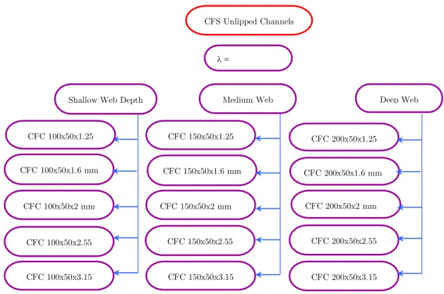
The geometric limitations given as per Direct Strength Method are satisfied for the sections chosen for the study. (Table 1). The specimens were analyzed as single unlipped channels to study their behaviour as shown in Figure 1.
Section Geom etric Lim itation
d/t< 472
b/t<159
0.7<d/b<5.0
Ø=90o
E/fy> 340(fy<593 MPa)
Table 1: Section Properties and Geometry. d
b
t
Latin American Journal of Solids and Structures 12 (2015) 1-17 Figure 1: Details of Studies Conducted.
AISI recommends the yield point of the steels to range from 172 to 482 N/mm2. Similarly AISI standards specifies the ultimate tensile strength of the steel to range from 289 to 584 N/mm2 and the ratio of tensile strength to yield strength ranges from 1.21 to 1.8. The recommended AISI mi-nimum percentage elongation ranges from 12 to 27. It is observed that the yield strength, ultimate tensile strength and percentage elongation of the chosen steel falls within the ranges specified by the AISI. The typical stress-strain behaviour of the tensile coupon for the specimens used in the nume-rical study is shown in Figure 2, Table 2 gives the respective mechanical properties.
Figure 2: Stress Strain Behaviour of the Coupon. 0
50 100 150 200 250 300 350
0 0,1 0,2 0,3
St
re
ss
(N
/m
m
2)
Strain (%)
E=196000 N/mm2, y=186 N/mm2
CFS Unlipped Channels
=
Shallow Web Depth Medium Web Deep Web
CFC 100x50x1.25
CFC 100x50x2 mm CFC 100x50x1.6 mm
CFC 100x50x2.55
CFC 100x50x3.15
CFC 150x50x1.25
CFC 150x50x1.6 mm
CFC 150x50x2 mm
CFC 150x50x2.55
CFC 150x50x3.15
CFC 200x50x1.25
CFC 200x50x1.6 mm
CFC 200x50x2 mm
CFC 200x50x2.55
Latin American Journal of Solids and Structures 12 (2015) 1-17
Young s
M odulus (E) (M Pa)
Y ield Stress (Fy) (M pa)
U ltim ate Stress (Fu)
(M pa)
Fu/Fy Percentage Elongation
196 186 319.06 1.72 18.7
Table 2: Material Properties of the Coupons.
3 FE MODELLING, ANALYSIS AND CALIBRATION
3.1 General
FEA of CFS plays an increasingly important role in engineering problems, as it is relatively inex-pensive and requires less effort and time compared to physical experiments, especially when a pa-rametric study of cross- section geometries is involved. Furthermore, it is difficult to investigate the effects of geometric imperfections and residual stresses of structural members experimentally. The FEA software nonlinear module ABAQUS version 6.10 is used to simulate the experimental beha-viour of fixed-ended CFS plain channel columns.
3.2 Element type and mesh
For performing static analysis general-purpose 4-noded shell elements (S4R) are appropriate and are adopted for most of the FE models. S4R elements with reduced integration with hourglass control and with finite membrane strains is used as shell element. Higher resolution of the transverse shear can be obtained by stacking continuum shell elements. C3D8R solid element is used to model the end plates, which are used to distribute the load over the column section. This element is defi-ned by 8-noded linear brick, reduced integration with hourglass control.
3.3 Boundary condition
Latin American Journal of Solids and Structures 12 (2015) 1-17
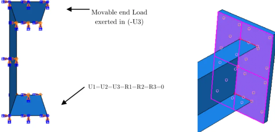
Figure 3: Ends with boundary condition and tie constraint.
3.4 Loading and analysis
Prior to analyzing the post-buckling behaviour the structure, linear buckling analysis is performed secondly on the specimens to obtain its buckling mode shape. The main purpose of the perturbation analysis is to establish probable buckling modes (eigen mode) of the columns. The eigen mode is then scaled by a factor (scale factor) to obtain a perturbed mesh of the column for the nonlinear analysis. The buckling analysis is carried out to predict the buckling loads and the corresponding buckling shapes. These are used as a parameter in determining the post-buckling strength and for incorporating the input values of the geometric imperfection by using first few buckling modes shape values. The buckling analysis is carried out for the eigenvalues of 50 by using LANCZOS eigensolver by applying an initial displacement of 1 mm at the point of application of the load. Then the displacement corresponding to local and overall buckling is added to get the total displa-cement. Figure 4 shows the first buckling mode and also the overall buckling modes.
Figure 4: Local and overall buckling modes respectively.
Movable end Load exerted in (-U3)
Latin American Journal of Solids and Structures 12 (2015) 1-17
The displacement control loading method is used, which is identical to the loading method used in the experiments. Nonlinear post-buckling analysis is carried out to study the load versus end-shortening characteristic curves and ultimate load capacity. Material and geometrical nonlinearity are applied to predict the experimental strength and behaviour.
3.5 Geometric Non-Linearity
While obtaining buckling deformation during nonlinear analysis, the column was assumed to have initial geometric imperfections. This was achieved by modelling the structure with an initial out-of-plane deflection. The scaled value of linear buckling mode shape was used to create an initial geo-metric imperfection for the non linear post buckling analysis. The degree of imperfection was assu-med as the maximum amplitude of the buckling mode shape and considered as a percentage of the elements thickness. Geometric imperfections were considered as a maximum local imperfection in the stiffened element and maximum deviation from straightness in the unstiffened element. Pekoz and Schafer (1996) suggested expressions for the average degree of imperfection for the cold-formed steel members was between 0.14t and 0.66t, where t is the thickness of sheet steel. Hence, in this study, the results based on the expression suggested by Pekoz were used. The local buckling imper-fection amplitude of 0.25t and the overall imperimper-fection amplitude of L/1000 were used for the axially loaded channels respectively. The section is loaded axially at the movable end by prescri-bing suitable increments of axial displacements. For each incremental step of end-shortening, the total load or reaction at the end is obtained. Modified Riks arc length method for equilibrium path is used in the analysis.
3.6 Verification
Latin American Journal of Solids and Structures 12 (2015) 1-17 Specimen PEXP (kN) PFEA (kN) PEXP/ PFEA
CFC 40x20x2.1 58.29 57.93 1.01
CFC 60x30x2.1 73.42 80.92 0.91
CFC 80x40x3.3 112.1 97.8 1.15
CFC 100x50x3.3 135.7 135.68 1.00
Mean 1.01
Standard Deviation 0.08
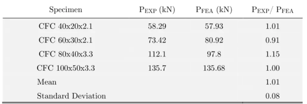
Table 3: Comparison of FEA and experimental results of unlipped channel columns tested by Vishuvardhan and Samuel Knight (2005).
The mean values and the standard deviation of the experimental and the FEA results are 1.01 and 0.08 respectively of 4 tests in Table 3, yet the second and third tests are 9 and 15 percent too low and too high, respectively similar to the studies conducted by BenYoung and Jintang Yan.Figure 5 shows the prediction by the experiment and FEA for the specimen 100x50x3.3. It can be observed that the deformed shapes of FEA and experiments are almost the same.
Figure 5: FEA and Experimental Deformed shape of CFC 100x50x3.3 mm.
4 PARAMETRIC STUDY
4.1 General
Latin American Journal of Solids and Structures 12 (2015) 1-17
Figure 6: Labelling of the Specimen.
NAS considers the effect of reduction in the effective section only in the calculation of effective area and effective section modulus, which are used to reduce the corresponding fully effective section strength. This may be a conservative or un conservative assumption.
4.2 Comparison of Ultimate capacities from design column strengths with FEA
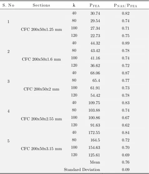
The column strength obtained from FEA is compared with the predicted design strength by NAS as shown in Tables 4 to 6. The mean and standard deviation for the ratio of FEA results to that of NAS prediction are calculated based on geometry, thickness and slenderness ratios. The mean and standard deviation of the PFEA to PNAS is 0.76-0.8 and 0.07-0.09 respectively. The prediction by
North American Standard is conservative for all the unlipped channels.
S. N o Sections PFEA PN A S /PFEA
1
CFC 100x50x1.25 mm
40 26.39 0.86 80 21.81 0.79 100 19.88 0.79 120 15.53 0.78
2
CFC 100x50x1.6 mm
40 43.76 0.80 80 35.74 0.92 100 24.72 0.95 120 20.86 0.84
3
CFC 100x50x2 mm
40 57.59 0.88 80 54.62 0.66 100 48.15 0.67 120 39.89 0.61
4
CFC 100x50x2.55 mm
40 93.00 0.75 80 88.25 0.57 100 77.06 0.58 120 65.22 0.51
5
CFC 100x50x3.15 mm
40 114.4 0.78 80 111.6 0.56 100 101.5 0.58 120 70.83 0.62
Mean 0.78
Standard Deviation 0.09
Table 4: Ultimate loads predicated by FEA and various Standards for web depth 100 mm and flange width of 50 mm.
Cold-Formed Channel
Web Depth
(mm) Flange Width (mm)
Thickness (mm)
Latin American Journal of Solids and Structures 12 (2015) 1-17
S. N o Sections PFEA PN A S/PFEA
1
CFC 150x50x1.25 mm
40 29.54 0.82
80 26.11 0.78
100 19.18 0.93
120 18.18 0.83
2
CFC 150x50x1.6 mm
40 43.73 0.87
80 39.75 0.80
100 39.61 0.70
120 29.95 0.78
3
CFC 150x50x2 mm
40 67.19 0.84
80 63.26 0.82
100 55.16 0.79
120 44.07 0.84
4
CFC 150x50x2.55 mm
40 96.32 0.88
80 91.24 0.79
100 75.62 0.81
120 69.67 0.83
5
CFC 150x50x3.15 mm
40 141.47 0.82 80 123.61 0.71 100 103.91 0.70
120 72.26 0.80
Mean 0.80 Standard Deviation 0.07
Table 5: Ultimate loads predicated by FEA and various Standards for web depth 150 mm and flange width of 50 mm.
Latin American Journal of Solids and Structures 12 (2015) 1-17
S. N o Sections PFEA PN A S/PFEA
1
CFC 200x50x1.25 mm
40 30.74 0.82
80 29.54 0.74
100 27.34 0.71
120 22.73 0.75
2
CFC 200x50x1.6 mm
40 44.32 0.89
80 43.42 0.78
100 41.16 0.74
120 36.62 0.72
3
CFC 200x50x2 mm
40 68.06 0.87
80 65.4 0.77
100 61.91 0.73
120 54.42 0.78
4
CFC 200x50x2.55 mm
40 109.75 0.83
80 103.88 0.74
100 100.86 0.67
120 91.63 0.62
5
CFC 200x50x3.15 mm
40 172.55 0.84
80 164.5 0.72
100 154.63 0.70
120 125.61 0.69
Mean 0.76 Standard Deviation 0.09
Table 6: Ultimate loads predicated by FEA and various Standards for web depth 200 mm and flange width of 50 mm.
4.3 Proposed column strength equation
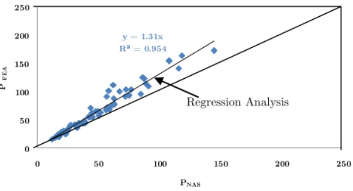
In general, the ultimate load carrying capacity predicted by FEA overestimates the results from experiments as shown in Table 2. This is probably due to the small values of residual stresses and rounded corners of the sections that were ignored in the FEA. Hence, a column strength equation is proposed. A regression analysis is done as shown in Figure 7 by comparing the the ultímate load carrying capacity from FEA (PFEA) and the predicted columns strengths by NAS (PNAS) for the 60
Latin American Journal of Solids and Structures 12 (2015) 1-17
y = 1.31x R² = 0.954
0 50 100 150 200 250
0 50 100 150 200 250
P
F
E
A
PNAS
Figure 7: Comparison curve of PFEA versus PNAS.
The proposed column strength equation for unlipped channels is
P*FEA = 1.31PNAS
Where P*FEA is the proposed column strength, PNAS is the ultimate load carrying capacity
predic-ted by NAS. The proposed column strength equation for the unlipped channels is calibrapredic-ted with the test results conducted by Ben Young and Jintang Yan (2002).
4.4 Comparison of experimental results with the recommended column strengths
The recommended column strengths (P*FEA) obtained from the regressive analysis is compared
with the experimental ultimate loads for the six specimens as shown in Table 7. The proposed equa-tion is generally conservative compared to the experimental results. The meanvalues of the propo-sed columns equation with NAS method (P*FEA/PNAS) and proposed columns equation with test
results (P*FEA/PExp) are 1.31 and 1.01 respectively.
S.No Specimen Identity
Experimental Ultimate Load
PExp (kN)
Predicted Ultimate Load
PNAS (kN)
Proposed Ultimate Load
(P*FEA)
P*FEA /PNAS
P*FEA /PExp
1 P36F0280 65.00 57.78 75.69 1.31 1.16
2 P36F1000 59.00 48.54 63.59 1.31 1.08
3 P36F1500 50.10 38.42 50.33 1.31 1.00
4 P36F2000 41.70 30.03 39.34 1.31 0.94
5 P36F2500 32.80 22.67 29.70 1.31 0.91
6 P36F3000 24.70 17.80 23.32 1.31 0.94
Mean 1.31 1.01
Table 7: Comparison of Experimental results with the Propsosed Equation.
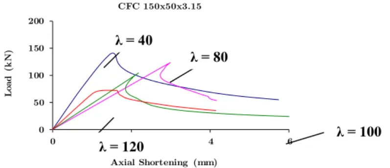
Latin American Journal of Solids and Structures 12 (2015) 1-17 4.5 Load versus Axial Shortening Behaviour
The behaviour of CFS unlipped single channels under axial loading, load versus axial shortening behaviour under elastic as well as plastic ranges of loadingthe effect of slenderness ratio, cross-section geometry of the unlipped channels on the load carrying capacity, and the mode of buckling of the unlipped channels have been studied. The Figures 8 to 10 show the load versus axial shorte-ning behaviour for the various slenderness ratios ranging from 40 to 120 for the shallow, medium and deep web depth plain channel sections with thickness 3.15 mm used for the parametric studies. During the initial stages of loading, all the curves show a linear relationship between the load and end-shortening. As the end-shortening increases and exceed the critical buckling loading, the co-lumns enter the post-buckling range, where nonlinear behaviour dominates. In the post-buckling range, the load increases progressively at a slower rate as the end-shortening increases.This can be noticed as the gradient of the curves is slightly gentler than that at the initial stage. At ultimate load, the columns failed and lost its ability to carry further loading. Therefore, the load curve de-creases with the end-shortening beyond the ultimate load. The load versus axial shortening beha-viour is initially linear in all the cases upto 80% of the ultimate load irrespective of the cross-section of the specimens. The initial stiffness is the highest for the least slenderness ratio. The co-efficient of ductility is more for the highest slenderness ratio compared to the lesser slenderness ratios. In all the cross-sections, there is a substantial increase in the load carrying capacity of about 50% for the decrease in slenderness from 120 to 40. The increase in the initial stiffness comparing slenderness ratio of 40 and 80 for CFC 200x50x3.15 mm is upto a margin of 40%.
0 50 100 150 200
0 2 4 6
L
o
a
d
(
k
N
)
Axial Shortening (mm)
CFC 100x50x3.15
Figure 8: Load versus Axial Shortening behaviour with varying λ
for CFC section 100x50x3.15 mm. λ = 40
λ = 80
λ = 100
Latin American Journal of Solids and Structures 12 (2015) 1-17
0 50 100 150 200
0 2 4 6
L
oa
d
(
k
N
)
Axial Shortening (mm) CFC 150x50x3.15
Figure 9: Load versus Axial Shortening behaviour with varying λ
for CFC section 150x50x3.15 mm.
0 50 100 150 200
0 2 4 6
L
oa
d
(
kN
)
Axial Shortening (mm)
CFC 200x50x3.15
Figure 10: Load versus Axial Shortening behaviour with varying λ
for CFC section 200x50x3.15 mm.
5 MODES OF FAILURE
The modes of failure for all channel sections observed from FEA studies shows that short and in-termediate channels failed either by local plate buckling and flexural buckling about the weak axis. The mode of failure and the location of the failure depend on the slenderness ratio and the cross-section of the cross-sections. Unlipped channel cross-sections with the lesser thickness fail by local buckling of the flange, which occurs between one third and mid-height of the specimens. Unlipped channel sections with slenderness ratio more than 100 predominantly failed by flexural buckling with local plate buckling in the flanges. In the case of deep web depth channels, the failure is initiated by local plate buckling for the short and intermediate columns. Long columns failed by overall bu-ckling which occurs between one third and mid height.
λ = 40
λ = 80
λ = 100
λ = 120
λ = 40 λ =
80
λ = 100
Latin American Journal of Solids and Structures 12 (2015) 1-17 6 CONCLUSIONS
Based on the review of the three international code provision and from FEA studies for the CFS unlipped channel sections subjected to axial compression, the following conclusions are drawn.
It is observed that for sections with 100 mm web depth, there is an increase in the load carrying capacity from 6 to 23% irrespective of the section and slenderness ratio.
The initial stiffness is 80% higher for sections with area of the web four times that of the area of the flanges.
There is a sudden drop in the ultimate load of the order of 30%, which is caused due to local buckling in the flanges for the specimens with the area of the web is thrice to the area of the flang-es. There is a gradual drop in the ultimate load for specimens with area of web twice to that of the area of flanges and the redection is of the order of 15%.
For the web depth being greater, there is a drastic decrease in the load carrying capacity for a given slenderness ratio.
With increase in the web depth from 100 mm to 200 mm, the load carrying capacity by FEA in-creases almost twice for the least slenderness ratio and upto 1.7 times for the higher slenderness ratio.
The failure observed is combined local buckling in the unstiffened element and minor axis flexural buckling for the slenderness ratio of 40 and 80 and the mode of failure for sections having slender-ness ratio 100 and 120 is predominantly by overall flexural buckling about the weak axis.
The North American Standards conservatively disregards the stress gradient and assumes uniform compression of intensity equal to the maximum compressive stress, over the entire width of the plate element.
For both the medium and deep web depth unlipped channel sections, the percentage of underes-timation is slightly more in NAS compared with FEA.
The load versus axial shortening behaviour is initially linear in all the cases upto 80% of the ulti-mate load irrespective of the cross-section of the specimens. The very long horizontal plateau after the ultimate load is noticed, which indicates high degree of ductility.
The initial stiffness is calculated for all the sections taken for the parametric study and it is ob-served that the initial stiffness for the sections with slenderness ratio of 30 is the greatest as com-pared to that of other slenderness ratios irrespective of whether lipped or plain sections.
All the unlipped channel sections fail by local buckling of the flange, which occurs between one third and mid height for the specimen with slenderness ratios of 40 and 80.
Unlippedchannel sections with slenderness ratio of more than 100 predominantly failed by flexural buckling with local plate buckling in the flanges.
The singly symmetric unlipped channel sections failed by local buckling of the flanges.
FEA predictions are proven to be in good agreement with the test results and hence it can be considered as an alternative to the experiments.
The proposed equation for the unlipped channels gives a higher bound and lower values for short and long columsn respectivelty.
Latin American Journal of Solids and Structures 12 (2015) 1-17 References
Anbarasu M, Amali.D, S.Sukumar 2013. New Approach to Improve the Distortional Strength of Intermediate Len-gth Web Stiffened. Thin Walled Open Columns. KSCE Journal of Civil Engineering, Vol. 17, No. 7, 1720-1727. Anil Kumar MV, Kalyanaraman V 2010. Evaluation of Direct Strength Method for CFS Compression Members without Stiffeners. Journal of Structural Engineering, Vol. 136, No. 7, 879-885.
Becque.J and Rasmussen.K.J.R 2009. A Numerical investigation of local-overall interaction buckling of stainless steel lipped channel columns. Journal of Constructional Steel Research. Vol. 65, No.8-9, 1685-1693.
Ben Young and Jintang Yan 2004 Numerical investigation of channel columns with complex stiffeners- part II: pa-rametric study and design. Thin Walled Structures, Vol. 42, 895-909.
Ben Young and Jintang Yan 2002. Finite Element Analysis and Design of Fixed-Ended Plain Channel Columns. Journal of Finite Elements in Analysis and Design. Vol. 38, 549-566.
Beulah Gnana Ananthi, Samuel Knight, Nagesh. R.Iyer and V.Marimuthu 2012. Behaviour of Cold-Formed Plain Channels Under Compression. Journal of Structural Engineering (SERC),Vol39, No 30, August-September 2012. pp: 237-244.
Beulah Gnana Ananthi.G, Samuel Knight G.M and Nagesh.R.Iyer 2012. Numerical Analysis of cold-formed Steel Open Sections under axial Compression. Journal of Structural Engineering (SERC), Vol.39, No.4, April-May 2012. pp: 13-20.
Chou.S.M, Chai.G.B and Ling.L 2000. Finite element technique for design of stub columns, Thin Walled Structures, Vol. 37, 97-112.
Lam.S.S.E, Chung.K.F and Wang.X.P 2006. Load Carrying Capacity of Cold-Formed Steel Cut Stub Columns with Lipped C-Section. Thin Walled Structures, Vol.44, 2006, pp 1077–1083.
Moharrami.M , Louhghalam A, Tootkaboni M 2014. Optimal folding of cold formed steel cross sections under Compression. Thin Walled Structures, Vol 76, pp145-156.
Macdonald.M and Rhodes.J 2005. Finite Element Modelling of Cold-Formed Stainless Steel Columns. Acta Polytechnica, Vol. 45 No.3, 92-98.
NAS Manual 2007. Cold-formed Steel Design Manual. American Iron and Steel Institute.
Pandian, N., Arul Jayachandran, S., Seetharaman, S. and Kad Vasanti Badasaheb 2003. Limit State Design of Cold-formed Steel Compression Members - Codal Comparisons. Journal of Structural Engineering. SERC, Vol. 30, No. 3, 173-178.
Vishnuvardhan.S and Samuel Knight. G.M (2007). Review of Codal Provisions for Cold-forming sections subjected to Compression. INSDAG S STEEL IN CONSTRUCTION. Vol. 8, No, 2, 31-42.