ABSTRACT: Concerns about the rising fuel price and environmental changes have led to the search for alternative fuels and energy sources. The interest in improving the performance of power generation, with the aim of reducing costs, increasing operating eficiency, and reducing the emissions of pollutants, has driven the scientiic community to work on new burning technologies. Flameless combustion is one of the best alternative new technologies for a clean and eficient one. The burning of liquid fuels in power generation and propulsion systems depends on the effective atomization to increase the surface area of the fuel and thus to achieve high rates of mixing and evaporation. This work described the spray characteristics of hydrous ethanol in a blurry injector for applications in a lameless compact combustion chamber. The experimental results are obtained over a range of relatively low low rates with different air-to-liquid mass low ratios.
KeywoRdS: Blurry injector, Hydrous Ethanol, Drop size, Discharge coeficients.
Experimental Valuation Diagnostics of
Hydrous Ethanol Sprays Formed by a
Blurry Injector
Claudia Gonçalves de Azevedo1, José Carlos de Andrade1, Fernando de Souza Costa1
INTRODUCTION
Spray combustion is extensively used in power generation and liquid-fueled rocket engines. In general, before burning, liquid fuels need to be dispersed in small droplets that are rapidly vaporized and mixed with the oxidizer. he atomization process increases the surface area of the fuel, aiming at making the contact area between the fuel and oxidizer higher and, therefore, its rates of mixing and fuel evaporation and in the time available for complete combustion. Efective fuel atomization is essential to minimize emissions of particulate matter (PM), carbon monoxide (CO), unburned hydrocarbons (UHC), and nitric oxides (NOx).
he increasing costs of fossil fuels, environmental concerns, and stringent regulations on fuel emissions have caused a signiicant interest for the use of biofuels. Ethanol has become an attractive alternative fuel for: it is a renewable energy source, easily available from common biomass sources, biodegradable, contributes to sustainability and is oxygenated, thereby providing the potential to reduce pollutants emissions. Due to its combustion characteristics, it also has been considered as a low polluting liquid propellant for the combustion rocket propulsion application (Gajdeczko et al., 2000).
he most typical mixing twin luid atomization technique is the air-blast atomization. Air-blast injectors have been widely used and studied (Lefebvre, 1992a, b; Clack et al., 2004; Hoeg et al., 2008; Bolszo and McDonell, 2009; Batarseh et al., 2010). In this technique, air and liquid are supplied separately to the injector, and mixing takes place downstream of the
1.Instituto Nacional de Pesquisas Espaciais – Cachoeira Paulista/SP – Brazil
Author for correspondence: Claudia Gonçalves de Azevedo | Instituto Nacional de Pesquisas Espaciais, Laboratório Associado de Combustão e Propulsão | Rodovia Presidente Dutra, km 40 | CEP 12.630-000 Cachoeira Paulista/SP – Brazil | E-mail: [email protected]
nozzle orii ce, externally. h e liquid discharges through a circular orii ce, while the air is supplied through an annular slot around the periphery, resulting in a conical discharge pattern. h e main atomization technique is shear interaction caused by high relative velocities between the air and liquid. A liquid jet is exposed to a stream of air l owing at high velocities, which impinge on the liquid jet outside the discharge orii ce, producing threads and ligaments. According to Lefebvre (1989), their initial hydrodynamic instabilities are augmented by aerodynamics disturbances, so that they expand away from the nozzle and their thickness slenderizes. When the ligaments collapse, droplets are produced. According to Lorenzetto and Lefebvre (1977), the air-blast injector produces i ner droplets as the supply pressure or mass l ow rate of the atomizing air is higher, which also increases the power requirement of the atomizer. However, the air blast injector performs poorly with fuels of high kinematic viscosity, creating large droplets that burn in dif usion mode to result in high PM, CO, and NOx emissions.
Another typical atomization technique of internal mixing type is known as ef ervescent atomization (Lefebvre, 1988; Lefebvre et al., 1988). A pressurized gas is injected into the bulk liquid in a mixing chamber, upstream of the discharge orii ce. h e injected gas forms bubbles to produce a two-phase mixture that l ows through the orii ce. h ey are expanded quickly when the mixture is exposed to a low-pressure zone at the injector exit, shattering the liquid into droplets. h ere have been many studies reported in the literature involving ef ervescent injectors over a range of air-to-liquid mass and liquid l ow rates (Lörcher et al., 2005; Konstantinov et al., 2010). According to Sovani et al. (2001), compared with an air blast injector, ef ervescent ones present advantages like the formation of a spray with i ner droplets over a wide range of operating conditions, even for less rei ned fuels; the injector performance is relatively insensitive to the liquid kinematic viscosity; the larger diameter of the orii ce alleviates clogging problems and simplii es fabrication.
Gañan-Calvo (2005) describes the l ow-blurring injector, or blurry injector, a novel twin l uid atomization technique, which exploits the advantages of internal and external mixes. h is injection method presents several advantages over other injectors, such as formation of a uniform spray, better atomization, high atomization ei ciency, robustness, excellent fuel vaporization and mixture with air, and potential for the application in compact combustion systems that can be used
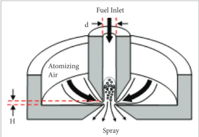
as portable power sources. Also, for a specii ed liquid l ow rate and total energy input, the l ow-blurring injector creates about 5 to 50 times more droplet surface areas than any other pneumatic injector of the “plain-jet air blast” type. Figure 1 presents the scheme of the l ow-blurring injector.
h e l ow-blurring injector consists of a fuel tube and an exit orii ce both of diameter (d). h e concept behind l ow-blurring atomization is that the air is forced through a small gap between the fuel tube exit and a coaxial orii ce located H distance downstream the fuel tube. As shown in Fig. 1, when H/d < 0.25, part of the air is forced a short distance into the fuel tube and the remaining produces shear layer as it leaves the injector orii ce enhancing the atomization process. h e back l ow of air at the tip of the fuel tube results in a two-phase turbulent l ow passing through a positive pressure i eld. h is mixture undergoes sudden decrease in pressure, while exiting through the injector orii ce. Due to the signii cant pressure decrease, air bubbles in the two-phase l ow expand and shatter the liquid into i ne droplets. h e l ow-blurring injector is capable of producing internal and external mixes of the two phases simultaneously, providing then superiority over other injectors.
Figure 1. Scheme of the l ow-blurring injector (Dent, 2012). Atomizing
Air
d
Fuel Inlet
Spray H
injector, using kerosene and diesel burning in a swirl stabilized combustor operated at atmospheric conditions, and verii ed that for such fuel and atomizing air l ow rates, the l ow-blurring injector produced three to i ve times lower NOx and CO emissions as compared to the air blast injector. Reduction in emissions was attributed to improved fuel atomization that resulted in a decrease in the mean droplet size for the l ow-blurring injector.
Sadasivuni and Agrawal (2009) used the l ow-blurring injector in a compact combustion system with a counter l ow heat exchanger. h e volumetric energy density of the system was substantially higher than that of the concepts previously developed. Heat release rate of up to 460 W was achieved in a combustor volume of 2.0 cm3. h e combustion system produced clean, compact, quiet, distributed, and attached l at l ame. No soot or coking problems were experienced during or at er combustor operation on kerosene fuel. Simmons and Agrawal (2010) used laser sheet visualization and a phase Doppler particle analyzer to obtain the spray characteristics of a l ow-blurring injector, operating with a coni guration where H/D=0.23 and using as working l uids water and air. h e authors also compared the performance of such injector with that of an air blast and from the results, they concluded that the l ow-blurring injector can ef ectively atomize liquids at relatively low air-to-liquid mass ratio (ALR) compared to the air-blast injector, while reducing the pressure drop penalty in the atomizing air line.
Rapid fuel vaporization and mixing with oxidizer are key requirements for liquid-fueled small-scale combustion systems. h us, the optimization of combustion systems is very attractive, since the use of non-renewable liquid hydrocarbon fuels is responsible for most of the energy production and pollutants emissions. h erefore, improvements in the design and operation of this equipment are essential for current environmental and energy requirements.
h e l ow-blurring injector is ef ective in generating a i ne spray for liquid fuels in mesoscale systems to promote vaporization. h erefore, this work presents the characterization of hydrous ethanol sprays formed by a blurry injector with a divergent exit. h e liquid and air mass l ow rates were measured experimentally and, since lower l ow rates and pressures were adopted, the injector will be considered for applications in a l ameless compact combustion chamber. Flameless combustion is a homogeneous low temperature
burning process leading to strongly reduced pollutant emissions and higher ei ciency compared to the traditional processes (Wünning and Wünning, 1997). Experiments are conducted for dif erent liquid and air mass l ow rates at ambient conditions of temperature and pressure.
EXPERIMENTAL SETUP
BLURRy INJeCToR
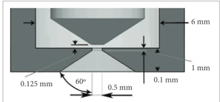
Figure 2 shows the injector developed that will be possibly used in a l ameless compact combustor. h e blurry injector consisted of a central liquid tube (d = 0.5 mm) and a coaxial atomizing air passage with 6 mm inner diameter. h e two-phase mixture exits through the orii ce of diameter (d=0.5 mm) in the discharge plate located, such that H=0.125 mm. As discussed, this geometry creates a turbulent mixing between the air and liquid phases at the tip of the liquid supply tube to produce a i ne spray.
Figure 2. Schematic representation of the blurry injector.
6 mm
1 mm
0.1 mm 0.5 mm
60º 0.125 mm
Test bench
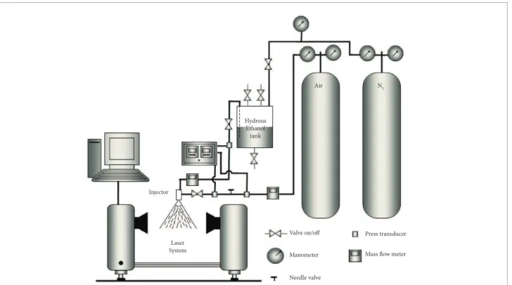
Compressed air was used as the atomizing gas and was supplied from a high-pressure cylinder, controlled by a needle valve, and measured by a calibrated l ow meter with an uncertainty of ± 1.5 standard liters per minute (slpm). h e l ow rates of hydrous ethanol were measured by rotameters, with the uncertainty in the measurements being ± 2%. Supply pressure in the fuel and atomizing air lines were measured using pressure transducers at locations depicted in Fig. 3.
( M a l v e rn Spraytec®
) at atmospheric conditions. h e operating principle of this system is the laser scattering produced by the droplets. h e laser dif raction system can measure droplet diameters from 0.1 to 2,000 µm with accuracy of ± 1% of full scale (specii ed by the manufacturer). It could measure the droplet size and distribution of sprays with obscurations up to 95% and calculates spray average properties along a sight line across the spray.
h e laser measurements were taken 50 mm downstream of the injector exit, where the spray drop size was constant further downstream. h e centre of the spray was positioned at the laser beam centre, so it could be fully covered by the laser beam.
Table 1 shows the properties of the hydrous ethanol. Density ρ, surface tension σ, and dynamic viscosity ν were determined by measurement in laboratory.
RESULTS AND DISCUSSION
Initially, the liquid flow rate was kept constant and the airflow rate was varied to obtain the variation in ALR in the injector. Then, the liquid flow rate was varied for different values of airflow rate. Air density was calculated considering the supply pressure and temperature of the atomizing air.
PReSSURe dATA
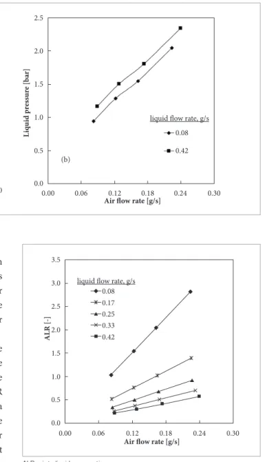
Figure 4 shows the pressure in the atomizing air line and the pressure in the hydrous ethanol one for dif erent air l ow rates. h e pressure measured was ef ectively that drop in the line because the injector was open to the room.
It can be seen in Fig. 4 that the air and liquid pressures in the injector increase with air l ow rate being higher. h e air pressure ranged from 1.02 and 2.88 bar for air l ow rate from 0.082 to 0.24 g/s, and the liquid pressure varied between 0.94 to 2.34 bar for air l ow rate from 0.082 to 0.24 g/s. h e pressure is higher when there is an increase of both air and hydrous ethanol mass l ow rates.
Figure 3. Schematic representation of the test bench. I njector
Hydrous Ethanol tank
Laser System
Manometer
Press transducer Valve on/off
N2
Needle valve
Mass flow meter Air
Table 1. Properties liquid fuel at 95 kPa.
Surface tension, σ (N/m)
density, ρ (kg/m3)
dynamic viscosity, ν (Ns/m2)
0.024* 806.7** 0.00124**
AIR-To-LIQUId MASS FLow RATIoS
h e ALR for the operational conditions are depicted in Fig. 5. To obtain the plots in Fig. 5 the liquid l ow rate was initially kept constant and the air l ow rate was varied over a range to obtain the variation in ALR. h e liquid l ow rate was then varied and the entire procedure was repeated for dif erent values of air l ow rate.
It is observed in Fig. 5 that for a given liquid l ow rate an increase in the air one leads to an increase in ALR. h e data in Fig. 5 also show an increase in ALR with a decrease in the liquid l ow rate. h e reason for the increase in ALR can be attributed to the fact that with the decrease in the area occupied by the liquid due to the decrease in its l ow rate the area available for air l ow increases, doing the same in the air l ow rate. For the liquid l ow rates analyzed, it was verii ed that the air l ow rate varied between 0.082 and 0.24 g/s and the ALR was seen changing from 0.21 to 2.88.
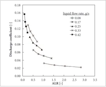
dISCHARGe CoeFFICIeNT
h e discharge coei cient is the ratio between the experimental mass l ow rate and the maximum theoretical mass l ow rate of the liquid in the injector. It is given by Eq. 1 (Delmeé, 1983):
cd = ml
A√2ρl∆Pl (1)
where cd is the discharge coei cient of the liquid; ml the experimental liquid mass l ow rate, kg/s; A is the total
cross-sectional area of the discharge orii ces, m2; ∆P
l is the pressure dif erence of the liquid l ow across the nozzle, Pa; and ρlis the density of the liquid, kg/m3. At each test condition, the discharge coei cient was determined by substituting into Eq. 1 the measured values of liquid l ow rate and pressure drop across the injector, along with injector l ow area and liquid density. Figure 6 shows the typical curve of the discharge coei cients versus ALR.
It is seen in Fig. 6 that for a given liquid l ow rate the discharge coei cient decreases with an increase in ALR. Lefebvre (1983) has dei ned the discharge coei cient to be a measure of the extent to which the liquid l owing through the i nal discharge orii ce
Figure 4. Air and liquid pressures. 2.5
2.0
1.5
1.0
0.5
0.0
A
ir p
ress
ur
e [b
ar]
Air flow rate [g/s]
0.00 0.06 0.12 0.18 0.24 0.30
(a)
0.08
0.42
liquid flow rate, g/s
2.5
2.0
1.5
1.0
0.5
0.0
L
iq
ui
d p
ress
ur
e [b
ar]
Air flow rate [g/s]
0.00 0.06 0.12 0.18 0.24 0.30
(b)
0.08
0.42 liquid flow rate, g/s
Figure 5. Air-to-liquid mass l ow ratio. 2.5
2.0
1.5
1.0
0.5
0.0
ALR [-]
Air flow rate [g/s]
0.00 0.06 0.12 0.18 0.24 0.30
0.08
0.42 liquid flow rate, g/s 3.0
3.5
0.17 0.25 0.33
makes full use of the availabl ow area. h erefore, the discharge
coei cient depends on the amount of l ow area available for the liquid phase. As ALR increases, the l ow area available for liquid decreases and Cd is inferior. h e rate of change in discharge coei cient decreases with an increase in ALR, which is responsible for a slower rate of decrease in the liquid l ow rate at higher values of ALR as seen in Fig. 6. h e values of discharge coei cient shown in Fig. 6 vary from 0.022 and 0.157 over the entire operating range.
dRoPLeT dIAMeTeR dATA
Dif erent characteristic diameters can be obtained to represent a spray. In this work, the Sauter mean diameter (SMD)
and the mass median diameter (MMD) were obtained with aid of the laser system. h e SMD is the droplet size that possesses a volume-to-surface-area ratio proportional to that of the entire spray, and MMD is the drop diameter such that 50% of the total mass of spray consists of droplets of smaller diameter.
Figure 7 illustrates the ef ect of ALR on the SMD and MMD at dif erent liquid mass l ow rates for hydrous ethanol.
h e results show that the droplet size is strongly inl uenced by the ALR. h e data presented in Fig. 7 conclude that the droplet size decreases with an increase in ALR for a given liquid l ow rate. It is verii ed that a decrease in liquid mass l ow rate causes a decreasing in the mean drop size. h e higher the ALR is, the higher the air l ux will be, and then a larger smashing energy can be provided for liquid atomization. It can be speculated that this decrease in the droplet diameter value is due to two ef ects. First, the increase in ALR increases the air l ow rate and the ef ective area occupied by air, decreasing the ef ective area occupied by liquid and liquid l ow rate through the injector orii ce. Increase in air l ow area is benei cial to atomization, because it reduces the area available for the liquid l ow, i.e. it squeezes the liquid into thinner i lms and ligaments as it l ows through the injector orii ce. Secondly, the increase in ALR is accompanied by one in exit velocities and turbulence inside the injector, resulting in improved atomization.
Figure 8 illustrates the ef ects of atomizing air velocity on SMD and MMD at dif erent liquid mass l ow rates for hydrous ethanol. Table 2 shows the ranges of ALR, air velocity, SMD, and MMD measured.
Figure 6. Discharge coefi cient versus air-to-liquid mass ratio. 0.02
0.00
D
is
ch
a
rge c
o
e
ffi
ci
en
t [-]
ALR [-]
0.0 0.5 1.0 1.5 2.0 2.5
0.08
0.42 liquid flow rate, g/s
0.17 0.25 0.33
3.0 3.5
0.06
0.04 0.10
0.08 0.14
0.12 0.18
0.16
ALR: air-to-liquid mass ratio.
Figure 7. Inl uence of air-to-liquid mass ratio on Sauter mean and mass median diameters. 14
12
10
8
6
4
S
M
D
[µ
m
]
ALR [-]
0.0 0.5 1.0 1.5 2.5 3.0
0.08 liquid flow rate, g/s
16
18 0.17
0.25 0.33
2.0 3.5
20 22 24
14
12
10
8
6
4
MMD [µm]
ALR [-]
0.0 0.5 1.0 1.5 2.5 3.0
0.08 liquid flow rate, g/s
16
18 0.170.25
0.33
2.0 3.5
20 22 24
Figure 8. Inl uence of air velocity on Sauter mean and mass median diameters. 14
12
10
8
6
4
S
M
D
[µ
m
]
Air velocity [m/s]
160 200 240 280 360 400
0.08 liquid flow rate, g/s
16 18
0.17 0.25
0.33
320 20
22 24
12
8
4
MMD [µm]
Air velocity [m/s]
160 220 280 400
0.08 liquid flow rate, g/s
16
0.17 0.25 0.33
340 20
24
SMD: Sauter mean diameter; MMD: mass median diameter.
Figure 9. Cumulative drop size distributions. 50
0
C
u
m
u
la
ti
ve
(
%
)
Particle Diameter (µm)
1 10 100
Dx(90)
ALR Dx(10) Dx(50)
1000 100
0.26 0.35 0.51
0.76 0.68
1.02 2.82
8.39 7.20 5.92
4.88 5.16
4.19 3.65
21.03 16.27 13.75
11.10 12.22
10.11 7.97
44.51 32.66 30.36
22.84 27.19
22.46 15.50
Table 2. Ranges of air-to-liquid mass ratio, air velocity and average diameters.
Liquid mass l ow rate (g/s)
ALR (-)
Air velocity (m/s)
SMd (µm)
MMd (µm)
0.08 1.04–2.82 176.96–304.49 10.37–6.59 14.53–7.97
0.17 0.52–1.40 181.37–309.27 10.71–7.20 14.27–9.17
0.25 0.35–0.93 185.04–313.30 11.75–8.97 16.27–12.13
0.33 0.26–0.70 188.27–316.82 14.17–10.41 21.37–14.40
REFERENCES
Batarseh, F.Z., Roisman, I.V. and Tropea, C., 2010, “Characterization of a spray generated by an airblast atomizer with preilmer”, Atomization and Sprays, Vol. 20, No 10, pp. 887-903.
Bolszo, C.D. and McDonell, V.G., 2009, “Evaluation of plain-jet air blast atomization and evaporation of alternative fuels in a small gas turbine engine application”, Atomization and Sprays, Vol. 19, No 8, pp. 771-785.
Clack, H. L., Koshland, C. P., Lucas, D. and Sawyer, R. F., 2004, “Development of an air-blast atomizer for independent control of droplet size and spray density”, Atomization and Sprays, Vol. 14, No 3, pp. 265-288.
Delmeé G.J., 1983, “Manual de Medição de Vazão”, São Paulo, Editora Edgard Blucher, 474 p.
Dent, T.J., 2012, “Mesoscale power generation incorporating heat-recirculation, porous inert media, and thermoelectric modules”, Ph.D. Thesis, University of Alabama, Alabama, USA.
Gajdeczko, B.F., Luff, J., Dryer, F.L. and Lavid, M., 2000, “Laser Ignition of Liquid Oxygen/Ethanol Propellants”, Twenty-Eighth Symposium (International) on Combustion, Abstracts of Work in Progress Poster Presentations (No. 2-B20), The Combustion Institute, Pittsburgh, PA, 244 p.
Gañán-Calvo, A.M., 2005, “Enhanced Liquid Atomization: From Flow-Focusing to Flow-Blurring”, Applied Physics, Letters 86.
Hoeg, D.P., Wang, Z., Friedman, P. D. and Laoulache, R. N., 2008, “Investigation of a coaxial air-blast atomizer using particle image velocimetry and computational luid dynamics”, Atomization and Sprays, Vol. 18, No 8, pp. 739-759.
Konstantinov, D., Marsh, R., Bowen, P. and Crayford, A., 2010, “Effervescent atomization for industrial energy–technology review”, Atomization and Sprays, Vol. 20, pp. 525-552.
Lefebvre, A.H., 1983, “Gas Turbine Combustion”, Hemisphere, Washington, D.C.
Lefebvre, A.H., 1988, “A novel method of atomization with potential gas turbine applications”, Defense Sciences Journal, Vol. 38, pp. 353-362.
Lefebvre, A.H., 1989, “Atomization and Sprays”, Hemisphere, New York.
Lefebvre, A.H., 1992a, “Energy consideration in twin-luid atomization”, Journal of Engineering for Gas Turbine, Vol. 114, pp. 89-96.
Lefebvre, A.H., 1992b, “Twin Fluid Atomization: Factors Influencing Mean Drop Size”, Atomization and Sprays, Vol. 2, No 2, pp. 101-119.
Lefebvre, A.H. et al., 1988, “Spray characteristics of aerated-liquid
pressure atomizers”, Journal of Propulsion and Power, Vol. 4, pp. 293-298.
Lörcher, M., Schmidt, F. and Mewes, D., 2005, Effervescent atomization of liquids, Atomization and Sprays, Vol. 15, pp. 145-168.
Lorenzetto, G.E. and Lefebvre, A.H., 1977, “Measurements of Drop Size on a Plain-Jet Airblast Atomizer”, AIAA Journal, Vol. 15, Issue 7, pp. 1006-1010.
Panchasara, H.V., Sequera, D.E., Schreiber, W.C. and Agrawal, A.K., 2009, “Emissions Reductions in Diesel and Kerosene Flames Using a Novel Fuel Injector”, Journal of Propulsion and Power, Vol. 25, No. 4, pp. 984-987.
Sadasivuni, V. and Agrawal, A.K., 2009, “A novel meso-scale Combustion System for Operation with Liquid Fuels”, Proceedings of the Combustion Institute, Vol. 32, pp. 3155-3162.
Simmons, B. and Agrawal, A.K., 2010, “Spray Characterization of a Flow-Blurring Atomizer”, Atomization and Sprays, Vol. 20, pp. 821-835.
Simmons, B.M., Panchasara, H.V. and Agrawal, A.K., 2008, “Effect of fuel injection concept on combustion performance of liquid fuels”, Proceedings of 2008 Technical Meeting of the Central States Section of The Combustion Institute, Combustion Institute, Pittsburgh.
Sovani, S.D., Sojka, P.E. and Lefebvre, A.H., 2001, “Effervescent atomization”, Progress in Energy and Combustion Science, Vol. 27, pp. 483-521.
Wünning, J.A. and Wünning, J.G., 1997, “Flameless Oxidation to Reduce Thermal No-formation”, Progress in Energy and Combustion Science, Vol. 23, Issue 1, pp. 81-94.
Figure 9 depicts the efects of A L R on cu mulative drop
size distributions and on representative diameters, Dx10, Dx50 and Dx90, i.e. the drop diameters such that 10, 50 and 90% of total liquid volume are in drops of smaller diameter.
he particle size distribution at a low ALR depicts the presence of larger droplets compared to the case of higher ALR, where the percentage of smaller size droplets have increased signiicantly, relecting an improved atomization at higher ALR. As expected, it was veriied that an increase in ALR leads to a decrease in droplet diameters, since the increase in air low results in better atomization.
![Figure 8. Inl uence of air velocity on Sauter mean and mass median diameters.141210864SMD [µm]Air velocity [m/s]1602002402803604000.08liquid flow rate, g/s](https://thumb-eu.123doks.com/thumbv2/123dok_br/18889158.424587/7.892.85.816.153.307/figure-uence-velocity-sauter-median-diameters-velocity-liquid.webp)
