ABSTRACT: This paper provides an overview of the design and development process of the L75 Liquid Propellant Rocket Engine (LPRE). Being developed at Instituto de Aeronáutica e Espaço (IAE), it is the irst Brazilian open-cycle liquid rocket engine pressurized by turbopump, designed to deliver 75 kN of thrust in vacuum as a cryogenic upper stage engine using liquid oxygen and ethanol. The Preliminary Design Review (PDR) was accomplished in December 2011 and December 2012 the project received from Agência Espacial Brasileira (AEB) a inancial support, through an agreement with Fundação de Desenvolvimento da Pesquisa (FUNDEP), to proceeding with the development of models and tests. The main components of the engine, briely described here, are thrust chamber assembly, gas generator, turbopump assembly, control system and ignition system.
KEYWORDS: Liquid propellant rocket engine, Liquid propulsion, Ethanol.
Development Status of L75: A Brazilian
Liquid Propellant Rocket Engine
Daniel Soares de Almeida1, Cristiane Maria de Moraes Pagliuco1
INTRODUCTION
he knowledge already acquired on technology of solid propellant rocket motors enables Brazil to have propulsion systems for small launch vehicles. In order to obtain commercially feasible vehicles, however, the inclusion of stages with liquid propulsion becomes a necessary condition. To obtain the technology and the know-how to design, manufacture, test and operate a Liquid Propulsion Rocket Engine (LPRE) is a goal to be achieved within the National Program of Space Activity (PNAE, 2012) in order to enable the development of satellite launch vehicles with higher performance and accuracy than solid propulsion.
he development of a LPRE is based on foremost scientiic methods and complex technological processes which require a heavy and long-term investment. he experience of other countries shows that the development cycle of a large liquid system is around ive to ten years. At the same time, many activities are necessary to involve the broad participation of research centers, universities and industries in the solution of multi-disciplinary problems.
he analysis of successful examples such as occurred in China, India, Japan and South Korea which had access to space ater the irst three — former Soviet Union, Germany, and the United States of America — shows that foreign partners had always been present in the initial stages of their development. It indicates that an investment in partnership is the key factor to overcome initial diiculties, mistakes and associated risks of the liquid propulsion technology (Niwa and Yoshino, 1997).
he LPRE propels space vehicles better than any other type of chemical propulsion, giving generally a higher speciic
1.Instituto de Aeronáutica e Espaço – São José dos Campos/SP – Brazil
Author for correspondence: Daniel Soares de Almeida | Praça Marechal Eduardo Gomes, 50 - Vila das Acácias | CEP: 12228-904 – São José dos Campos/ SP – Brazil | Email: [email protected]
impulse compared with solid or hybrid rockets. Usually, the cryogenic propellants have the highest specific impulse in liquid rocket engines.
Some of the most important advantages of LPREs are the very wide range of thrust values to it speciic applications, multiple ignition possibility, fast pulsing, long term operation time and ready to reuse; thrust variation upon command; controlling attitude changes and the capability to be checked and even fully tested before use.
he restart of the LPRE thrust allows an accurate terminal flight velocity, which is important to achieve the required orbit. A remarkably high reliability has been achieved in the production of LPREs besides their lightweight structure, enabling more embedded payload for a mission. Most exhaust gases of LPREs using modern common propellants are non-toxic and environmentally friendly (Sutton, 2006).
he cryogenic propellant liquid oxygen (LOx) and liquid hydrogen (LH2) produce the higher speciic impulse available for all environmentally friendly bipropellant, which permit a considerable increase in cargo delivery for rocket launchers. However, cryogenic components have big issues with evaporation, which limits the duration of the mission light. In addition to that, LH2 has the disadvantage of needing big tanks due to its very low density.
he second more energetic and also non-toxic propellant pair is the LOx and kerosene, which has lower speciic impulse but higher density and a prolonged service in space rather than LOx/LH2. LPRE with this propellant combination is suitable for both irst and upper launcher stages.
Moreover, although less energetic, the LOx and ethanol propellant pair has the advantages of its ready availability in Brazil, its chemical composition uniformity, being non-toxicity, its cleanliness, its low cost, and it does not sufer pyrolysis or produces signiicant soot at high temperatures inside the cooling channels of the regenerative cooled combustion chamber (Haeseler et al., 2000).
Engines with higher speciic impulse are, in order, those using LH2 and LOx as propellants and those operating in closed cycle. However, the technological challenges of using LH2 as propellant and the design of a closed cycle engine would make its development in the country still more complex than that of an open cycle engine using LOx and ethanol.
here are several diferent designs whereby a turbine can be integrated into a LPRE, and this was identiied as diferent engine cycles. he open cycle has a separate gas generator, where fuel
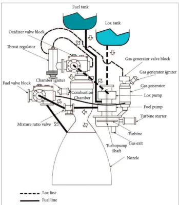
and oxidant are burned at a speciic mixture ratio, resulting in the low temperature of the turbine inlet gases to prevent destruction of the turbine blades. his cycle is the simplest, and it oten ofers the lowest overall cost, provides a low engine structural mass due to lower internal pressure, but gives somewhat not higher performance than the closed cycle, which is more complex in design, manufacturing and testing. Figure 1 shows the L75 scheme, a LPRE with a typical open cycle (Torres et al., 2009).
THE L75 ENGINE CHALLENGE
he current Brazilian Satellite Launcher Vehicle (VLS-1) cannot meet the overall strategic objectives of the space sector. However, it is envisaged the possibility to signiicantly increase the payload capacity of VLS-1 through partial modiication of the vehicle, especially with the replacement of the solid propellant motors by liquid propellant engines in an upper stage.
To achieve this goal, several activities have been conducted in Instituto de Aeronáutica e Espaço (IAE) such as the speciication, design and construction of liquid rocket engines. One of these projects is the L75 engine.
A timeline of the project with the major milestones is: • 2008 – Beginning of the L75 project;
• 2009 – System Requirement Review (SRR);
• 2010 – 2012 – FUNCATE (Fundação de Ciência, Aplicações e Tecnologia Espaciais) contract: technical service to support development of the project - 20 specialists; • 2011 – Preliminary Design Review (PDR);
• 2012 – Letter of exchange for Brazilian-German cooperation on the development and tests of a 75 kN engine;
• 2013 – Fuel change from kerosene to ethanol;
• 2013 – 2015 – FUNDEP agreement: to proceed with the development, manufacturing and test of some components.
agreement between the IAE and the DLR to the development and tests of a 75 kN LOx-ethanol were organized.
he L75 development is being based on the ECSS standards (ECSS, 2004), using development (DM), engineering (EM) and qualiication (QM) models engine components, parts and subsystems in order to verify the conformance to requirements. A veriication program was established through an engine development plan, according to the L75 engine requirements speciications, considering the veriication methods, levels and models.
For the L75 engine project, it is imperative to prioritize the development and mastery of critical space technologies, which are essential to the industrial progress, and the achievement of the necessary national autonomy in such a strategic activity. he allocation of speciic system engineering requirements and needs to the L75 engine depends strongly on the type of agreement established between customer — IAE — and supplier — Brazilian enterprises — and the nature and level of complexity of the overall system subject of the agreement. he system engineering organization plans its activities in conformance with the project phases as deined by the management, in accordance to the European Cooperation for Space Standardization (ECSS) standards (ECSS, 2009).
The L75 engine needs, program objectives and requirements identified in the present concept phase are
listed below. These requirements are preliminary in nature and not yet complete.
he project needs and objectives identiied by IAE are: • Consolidating the Brazilian space industry, by increasing
its competitiveness and innovation capacity;
• Encouraging funding of programs based on public or private partnership;
• Enabling Brazilian suppliers for manufacturing, brazing and welding processes;
• Encouraging the human resources development by training of experts needed in the Brazilian space activities, both domestically and abroad;
• Expanding partnerships with other countries, by prioritizing joint development of technological and industrial projects of mutual interest;
• Developing of the controlling, monitoring, transmission and the data log related to the project;
• Developing of high complexity turbopump technology; • Developing of an upper stage engine for a launch vehicle
capable to carry a payload;
• Developing of staf and enterprises on liquid propulsion activities.
Some tasks are not addressed to the L75 engine project, such as the launcher vehicle, the stage, the propellant tanks systems, the inert gas supply system, and the thrust vector control system.
he critical technologies considered for the development of L75 engine are feasible materials for speciic applications; bearings for the high rotation and low temperature operational conditions; seals for cryogenic application; welding and brazing process; development of cryogenic items as valves and regulators; regenerative thrust chamber; system feeding by turbopump; control system; assemblies and integrations; development of heat treatment ater brazing for copper alloy and test facilities.
L75 ENGINE MAIN
CHARACTERISTICS
he main high-level function of the L75 engine is providing (75.0 ± 5.0) kN of nominal thrust in vacuum with the main operation conditions shown below:
• Speciic impulse greater than 2,940 m/s in vacuum; • Minimum mission burn time of 400 s;
• Global mixture ratio in the range of 1.50 to 1.95;
• Total pressure inside of the combustion chamber in the range of 5 to 7 MPa.
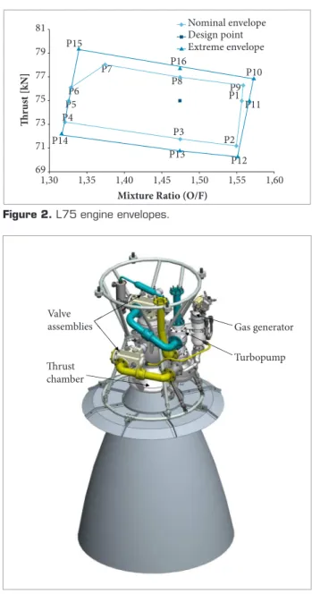
he L75 engine nominal and extreme operational envelopes, a set of physical data in which the propulsion system, subsystem, or component is intended to operate, are shown in Fig. 2.
The results obtained show that the L75 engine in the current coniguration has a decent mixture ratio envelope, despite a small margin for thrust variation. he restrictive factors are the thrust chamber maximum mixture ratio, the gas generator maximum and minimum mixture ratios and the turbopump maximum fuel low.
he L75 engine (Fig. 3) thrust chamber consists of three main components, the combustion chamber, where the propellants undergo a set of chemical reactions at high pressure creating hot gases during the combustion process; the nozzle, where the hot gases are accelerated to supersonic velocities; and the injector head, where the propellants are introduced, broken up into small liquid droplets and distributed over the cross section of the burning region inside the combustion chamber. he thrust chamber cooling is a major challenge because the gas temperature exceeds the melting point of the metallic wall. To overcome this problem, the L75 engine uses a lightweight brazed and welded cooling jacket with a thin inner-wall construction.
he turbopump is one of the most critical components during the development of a LPRE, since it is a high-precision and high-speed rotating machinery operating in critical conditions. he main goal of the turbopump is to feed the thrust chamber and gas generator with the necessary low and pressure of fuel and oxidizer provided by the pumps, which are driven by the turbine. Its manufacturing is expensive, and its design is complex and demands a great efort of engineering.
here are many diferent types of valves within the L75 engine project, such as fuel and oxidizer valves, vent valves, gas valves, pressure-regulating valves, check valves, thrust regulator, drain valves and safety valves. Most of the commercially available valves do not fulill the engine requirements, are too heavy, or are not available for the Brazilian space program. For those reasons, most valves and regulators are being developed. he L75 engine will operate with a thrust regulator, which is capable to regulate the LOx pressure for the gas generator, modulating the turbine power, which relects on the turbopump
shat speed and pumps power. It is also equipped with two main valve assemblies, one for LOx and another for ethanol. Both of them are very similar in coniguration and their functions cover chill-down/illing bypass, gas purging, pressure safety relief, opening at the start-up sequence and closing at the shutdown sequence. he aim of the L75 ignition system is to achieve a safe, predictable, and reliable transition to nominal thrust in vacuum. he ignition system devices include a turbine starter, gas generator igniter, thrust chamber igniter and pyrotechnic actuators.
he L75 engine igniter and the turbine starter are based on the operating principles of solid rocket motors, consisting of a metallic structure, an electro-pyrotechnic starter, a reinforcement
Thr
us
t [kN]
Mixture Ratio (O/F) 1,30 81 79 77 75 73 P1 P2 P3 P4 P6 P5 P7 P8 P9 P10 Nominal envelope Extreme envelope Design point P11 P12 P15 P16 P13 P14 71 69
1,35 1,40 1,45 1,50 1,55 1,60
Figure 2. L75 engine envelopes.
Turbopump� Gas�generator� Thrust� chamber� Valve� assemblies� Turbopump� Gas�generator� Thrust� chamber� Valve� assemblies� Valve
assemblies Gas generator
Turbopump Thrust
chamber
he development life cycle phasing was elaborated according to ECSS system, but this system can be adapted to speciic domains of application by use of tailoring activities necessary to meet specific project needs. The engine development is divided into ive main phases: mission identiication, feasibility (concept), preliminary design (development), detailed design (engineering) and qualiication.
Besides, the development models on thrust chamber, turbopump and gas generator (power pack), valves and regulators and control system level, two DM, one EM and two QM on engine level are considered the minimum necessary for engine development.
The two qualification models will be subject to all essential modifications needed to meet the requirements of the engine specification.
All engine components shall pass by acceptance tests before their integration to the engine.
The selected basic approach is to minimize the overall technical risk and to reduce non-recurring cost during development by use of demonstrated hardware designs as much as possible.
cartridge, the main cartridge propellant, and the thermal protection and nozzle.
he control system of the L75 engine is responsible for the starting procedure and ensures a safe transition to nominal thrust in vacuum; to achieve the desired thrust by controlling the fuel and oxidizer low rate and pressure drops; safe shutdown of the iring operation. Furthermore, additionally controlled features are the precision of the automatic thrust control, mixture-ratio control and condition monitoring (safety controls or health monitoring of the engine).
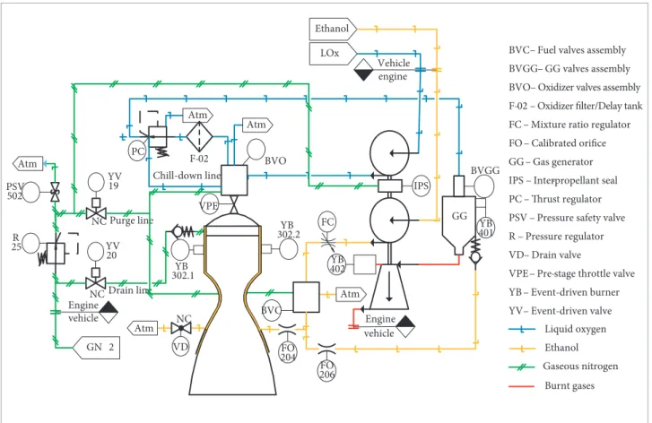
A low diagram of the L75 engine showing its components is given in Fig. 4.
DEVELOPMENT LOGIC
he development and qualiication philosophy dedicated to the L75 engine and its subsystems are presented in Fig. 5, where the hardware model low is shown.
GG YV 19 YV 20 NC BVGG BVC VD R 25 BVO PSV 502 GN 2 Atm Atm Atm YB
302.2 401YB
YB 402 F-02 Vehicle engine NC NC vehicle Engine LOx Ethanol Atm YB 302.1 FO 204 FO 206
BVC – Fuel valves assembly
BVGG – GG valves assembly
BVO – Oxidizer valves assembly
F-02 – Oxidizer filter/Delay tank FC – Mixture ratio regulator
FO – Calibrated orifice
GG – Gas generator
IPS – Inter-propellant seal
PC – Thrust regulator PSV – Pressure safety valve
R – Pressure regulator
VD – Drain valve
VPE – Pre-stage throttle valve
YB – Event-driven burner
YV – Event-driven valve Purge line Drain line Chill-down line Atm IPS VPE PC FC Liquid oxygen Ethanol Gaseous nitrogen Burnt gases vehicle Engine
OVERALL DEVELOPMENT STATUS
Until the end of 2012, the L75 project was developed using, in addition to the IAE’s human resources, services based in a contracts with FUNCATE. his contract had a technical and service expertise as an objective to support technology development of the L75. In December 2012, the project received from AEB a inancial support, through an agreement with FUNDEP, to proceed with the development of the irst components, allowing proceeding with the needed tests to conirm the design parameters. his agreement seeks to give more lexibility to the development of the project and involved Brazilian industries in the space program.
GAS GENERATOR
he gas generator is a combustion device used in LPREs for creating gases in suitable conditions, which are used as a working luid for driving the turbine of the turbopump.
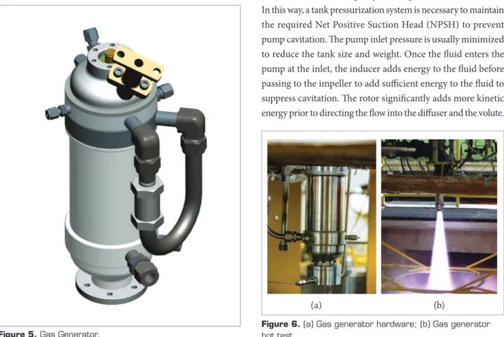
he basic elements of the gas generator (Fig. 5) are: injector element, cylindrical section, convergent section, in addition to ixing structural elements and interfaces. he igniter of the gas generator is part of the ignition system. he L75 gas generator
has a mass low rate of 1.3 kg/s, a mixture ratio of 0.3 and gas temperature of 900 K.
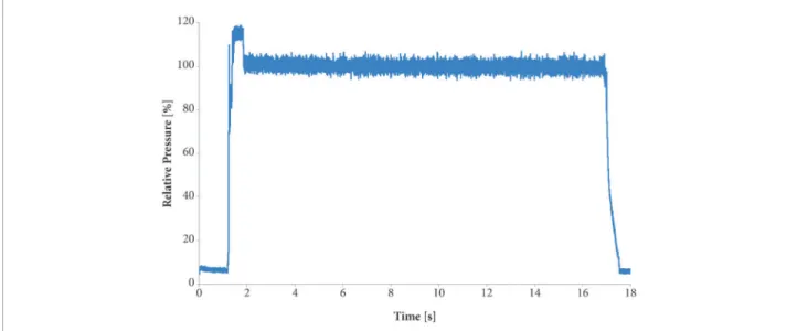
he irst L75 gas generator was tested in April 2014 on IAE’s 20 kN test bench (Fig. 6). hese tests are used in order to verify the overall component performance, the combustion process and to validate thermodynamic models used during the design. Figure 7 shows the gas generator relative chamber pressure versus the time during a hot test, demonstrating its stability.
TURBOPUMP
The L75 turbopump (Fig. 8) shaft is supported by two bearings, which are centrally mounted close to the fuel pump, so they can be lubricated and cooled by the fuel. Seals are also provided to limit leakage.
Considering cavitation characteristics and the fuel rich gas on turbine side, the LOx pump is located at one end of the shat and the fuel pump in the middle, connected by a spline between pumps and a shat. he gas generator exhaust ducting leads to an impulse type single stage axial low turbine with partial admission. Between the two pumps, an inter-propellant seal is adopted to avoid any interaction between propellants.
he luid enters the pumps at low pressure from the tanks. In this way, a tank pressurization system is necessary to maintain the required Net Positive Suction Head (NPSH) to prevent pump cavitation. he pump inlet pressure is usually minimized to reduce the tank size and weight. Once the luid enters the pump at the inlet, the inducer adds energy to the luid before passing to the impeller to add suicient energy to the luid to suppress cavitation. he rotor signiicantly adds more kinetic energy prior to directing the low into the difuser and the volute.
Figure 5. Gas Generator.
Figure 6. (a) Gas generator hardware; (b) Gas generator hot test.
he turbine’s (Fig. 9) main characteristics are power of 380 kW; inlet gas pressure of 5.0 MPa; outlet gas pressure of 0.4 MPa; gas low rate of 1.3 kg/s; temperature in the blades of 800 K, rotation speed of 24,000 rpm. he oxidizer pump works with
inlet pressure of 0.4 MPa; outlet pressure of 7.6 MPa; and mass low rate of 14.5 kg/s. he fuel pump works with an inlet pressure of 0.3 MPa; an outlet pressure of 10.6 MPa; and a mass low rate of 9.4 kg/s (Fig.10).
Figure 7. Gas generator relative chamber pressure versus time during a hot test.
LOx pump rotor Fuel pump
Turbine
Figure 8. (a) Turbopump; (b) Rotor assembly.
Figure 9. (a) SAE 422 stainless steel turbine disk; (b) Finite element analysis of distribution of temperature on turbine disk. (a)
(a)
THRUST CHAMBER
he main characteristics of the thrust chamber are: mass low of 22.8 kg/s; mixture ratio of 1.7; temperature in the combustion chamber of 3400 K; and area expansion ratio of 150. Figure 11 shows the L75 thrust chamber in the short coniguration for sea level hot tests.
COMPONENTS
he main characteristics of the L75 thrust regulator (Fig. 12), responsible for the control of the thrust level, are the nominal mass low rate of 0.3 kg/s (LOx); the inlet pressure of 7.0 MPa and the outlet pressure of 6.0 MPa.
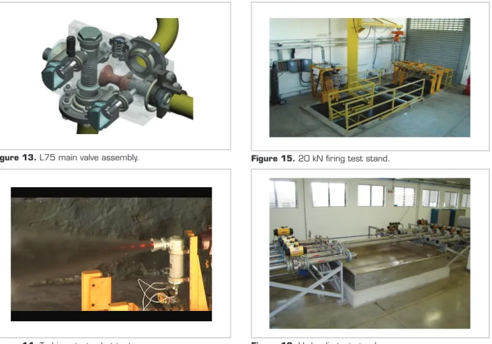
L75 will operate with two main valve assemblies (Fig. 13) with the following parameters: LOx inlet pressure 7.5 MPa; nominal LOx mass low rate 14.5 kg/s; ethanol inlet pressure 10.6 MPa; ethanol mass low rate 9.4 kg/s.
The ignition of the L75 engine is a challenging issue. he dominating criterion is reliability, repeatability and robustness of the ignition system (Jean and Dalbies, 2000).
Several tests have already been executed with the thrust chamber and gas generator igniters and the turbine starter, as can be seen in Fig. 14.
TEST FACILITIES
Liquid rocket engines for launch vehicles as well as their subsystems need to be veriied and qualiied during cold and hot-runs. A high test cadence combined with a lexible test team helps to reduce the cost for test veriication during development and qualification as well as during acceptance testing for
Figure 11. (a) thrust chamber; (b) equivalent stress in MPa (von Mises stress).
Figure 12. Thrust regulator valve. (a) Figure 10. AA 7075 aluminum alloy high-speed rotor
pumps (a) ethanol and (b) LOx.
(a) (b)
(b)
he basic strategies for development and veriication of the L75 engine are based on appropriate veriication methods of the requirements, levels that the component occupies in the product tree, stage of development and deinition for the development, engineering and qualiication models. One or more models may be required to demonstrate compliance with speciied requirements of the design, depending on the level of veriication. Acceptance tests will be carried out on component, equipment and engine level. Prior to acceptance test, these items should be checked-out according to the deined assembly or integration procedures.
To conirm adequacy of the design methodology of L75 engine, the construction of test facilities is in progress. he test benches in operation or under implementation are described hereater.
20 KN FIRING TEST STAND
Designed for iring MFPLs up to 20 kN of thrust using pressurized tanks of LOx and ethanol as a propellant and with a combustion chamber pressure up to 100 bar. his test bench, which currently is used for testing the engines L5 and L15, was adapted for the L75 gas generator hot tests (Fig. 15).
HYDRAULIC TEST STAND
The hydraulic test stand is a facility whose main objective is the characterization of LPRE components, using distilled water as working fluid. It consists basically of the specimens test area, the drive system consisting of pumps and electric motors, the distilled water storage tank, a filtration system, water cooling system and the data acquisition and control systems, which is able to achieve a water flow up to 30 kg/s, working pressure of 35 bar. The system power is 180 HP (132kW). Figure 16 shows the test area of the hydraulic test stand.
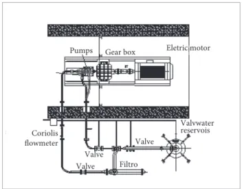
PUMPS AND TURBINE COLD TEST STAND Pumps and turbine cold test stand will allow the testing of the L75 hydraulic pumps and turbine through the operation of individual pumps and turbine, control of components and data acquisition allowing the veriication of functional requirements of these pumps and adequacy of the design of the component being tested. Figure 17 shows the scheme of the pumps and turbine cold test stand.
Figure 13. L75 main valve assembly.
Figure 16. Hydraulic test stand. Figure 14. Turbine starter hot test.
Eletric motor
Filtro
Valvwater reservois
Valve Valve
Valve Coriolis
flowmeter
Gear box Pumps
Figure 17. Scheme of the pumps and turbine cold test stand.
FUTURE AND CONCLUSION.
The greatest merit of the L75 project is not only the development of the engine which is, in itself, already a great contribution to formation of a qualiied team, implementation of infrastructure for design, manufacturing using qualiied Brazilian
enterprises and testing, but mainly driving the country on a new technological level to actually be able to open access to space.
he next project critical activities are: manufacture of thrust chamber, turbopump, valves and regulators and cold and hot tests of these models.
Usually, in a rocket engine development, from conception through qualification for flight, the cost of design and manufacture, which is the actual stage of L75 development, corresponds approximately to 20% of the total costs. herefore, if Brazil indeed masters this long-term technology will be necessary more investments in human resources, infrastructure, manufacturing, etc.
ACKNOWLEDGES
his paper was elaborated with support of a large number of members of the IAE and FUNDEP, and the authors wish to thank the team members.
he authors thank AEB for the inancial support.
REFERENCES
ECSS – European Cooperation for Space Standardization, 2004, “ECSS-E-30 part 5.2 draft1 rev.1”, Propulsion for Launchers – Solid and Liquid.
ECSS – European Cooperation for Space Standardization, 2009, “ECSS-M-ST-10C”, Project planning and implementation.
Haeseler, D., Götz, A. and Fröhlichs, A., 2000, “Non-toxic propellants for future advanced launchers propulsion systems”, AIAA – 2000-3687.
Jean, F. and Dalbies, E., 2000, “Development status of the VINCI engine for Ariane 5 upper stage”, AIAA/ASME/SAE/ASEEE 36th Joint Propulsion Conference and Exhibit, Hunstsville – USA.
Niwa, M. and Yoshino, T., 1997, “Liquid Propulsion in Brazil”, COBEM 97.
PNAE – Programa Nacional de Atividades Espaciais 2012-2021: AEB - Agência Espacial Brasileira, 2012, Ministério da Ciência e Tecnologia, Brasília, Brazil.
Sutton, G.P., 2006, History of Liquid Propellant Rocket Engines, Virginia, USA: American Institute of Aeronautics and Astronautics, Inc., 911 p.