ABSTRACT: Nitrous oxide is a monopropellant with potential for use in propulsion systems for orbit correction, positioning and attitude control of satellites. This paper presents experimental results with a 2N thruster prototype employing nitrous oxide gas decomposed by a rhodium oxide catalyst supported on alumina. Initially, the thruster design, the test bench and test procedures are described. Then the main experimental results, including thrust curves, mass low rates, pressures and temperatures along the thruster are presented for pulsed operation. At the end speciic impulses, characteristic velocities and thruster eficiencies are determined, thus indicating a catalytic decomposition eficiency of about 88%.
KEYWORDS: Satellite propulsion, Nitrous oxide, Rhodium oxide catalyst, Propulsive eficiency.
Experimental Investigation of a
Monopropellant Thruster Using Nitrous Oxide
Luciano Hennemann1, José Carlos de Andrade1, Fernando de Souza Costa1INTRODUCTION
Several factors, such as atmospheric drag, the gravitational attractions of the Moon and the Sun, the non-uniformity of the Earth gravitational ield and solar radiation contribute to change the attitude and move satellites from their original orbits (Sutton, 2001). For example, in geo-stationary satellites, Luni-solar perturbations cause a north-south drit that requires corrections of 50 m/s/year and the variation of the Earth gravitational ield can generate an east-west drit of 1 degree in 60 days (Stark and Swinerd, 2003). herefore, the use of an orbit correction and attitude control system is necessary for continuity of the normal service conditions of a satellite.
At irst, the control system of the rocket launcher provides input for the upper propulsion stages, for initial stabilization in orbit, alignment and iring of small thrusters (actuators). These are responsible for positioning and attitude control of the satellite in its initial orbit, having sensors, algorithms and actuators to aid in these tasks. he sensors determine the satellite’s instantaneous position in orbit and provide reference to an algorithm that controls the thrusters to reposition the satellite (Plumlee and Steciak, 2004; Sanscrainte, 1961).
Liquid propellant thrusters can generate high specific impulses and thrusts, and allow precise control of thrust and exhaustion kinetic energy. In general, these systems use pressurizing tanks with an inert gas (nitrogen or helium). In bipropellant systems, the fuel and oxidant are injected, mixed and burned in the combustion chamber to form gaseous products at elevated temperatures that are ejected through a nozzle to generate thrust. Monopropellant thrusters use a single propellant decomposed by a catalyst, or by heating, in order to form hot gases to be ejected at high speeds through the nozzle.
1.Instituto Nacional de Pesquisas Espaciais – Cachoeira Paulista/SP – Brazil.
Author for correspondence: Luciano Hennemann | Laboratório Associado de Combustão e Propulsão – Instituto Nacional de Pesquisas Espaciais | Caixa Postal 1, Cachoeira Paulista/SP | CEP: 12.630-000 – Brazil | Email: [email protected]
Both systems can operate in pulsed mode for attitude control and orbit correction and stay idle long periods of time. However, liquid monopropellant systems can provide smaller and more precise pulsed irings and have a lower number of components compared to bipropellant systems. hese can be expensive and diicult to be applied in some cases, and require care in the design to operate with zero gravity (Brown, 1995; Humble et al., 1995). he use of monopropellant or bipropellant systems depends on the desired application. Comparatively, bipropellant systems have speciic impulses between 300 s to 450 s, producing a thrust up to 1.2×10⁷ N. Monopropellant systems operate with speciic
impulses of 130 s to 280 s providing 0.5 N to 500 N of thrust (Makled and Belal, 2009). Nevertheless, monopropellant systems are more commonly used than bipropellant systems for orbit correction and attitude control of satellites due to the low thrust levels required, lower mass and greater simplicity in construction. Hydrazine (N2H4) is the most used liquid monopropellant for space applications; however, in the last decade, there has been a signiicant interest for using green monopropellants, such as nitrous oxide (N2O) and hydrogen peroxide (H2O2). Nitrous oxide can be used as an energy source and for generation of oxygen on board spacecrats or launch rockets, in cold gas propulsion systems for attitude control, in monopropellant or bipropellant thrusters, in gas generator systems, turbine operation and resistojets (Zakirov et al., 2000).
A research team from the University of Surrey, in England, has tested several catalysts for decomposition of nitrous oxide. he tests were performed without choking the nozzle, at ambient pressure. he reported temperature for initiation of decomposition was 250°C and the final decomposition temperature reached 1500°C. It was concluded that the catalytic decomposition process depends on the mass low rate and also that the start of the catalytic decomposition can be faster with higher preheat energy supply (Zakirov et al., 2001).
At Tsinghua University, in China, hot tests were made with nozzle chocking. Based on the research from the University of Surrey, the catalytic bed dimensions were reduced and the transient preheat time decreased from 15 min to 52 s (Zakirov and Li, 2004). Also in Tsinghua, a computational model of the operation of a nitrous oxide monopropellant thruster was developed (Zakirov and Zhang, 2008).
In Surrey and Tsinghua Universities, the focus of research was in the decomposition of nitrous oxide. In contrast, researchers at Stanford University evaluated the characteristic velocity eiciency and predicted the thrust of a nitrous oxide thruster,
although without providing information on the thruster design. A gas generator was developed to operate at high mass low rates of nitrous oxide ranging from 0.9 g/s to 2.3 g/s, thus obtaining characteristic velocities with high eiciency in steady state. he mixing of CH4 and N2O was also studied for initiation of the reaction (Lohner et al., 2007; Scherson and Lohner, 2009).
In the University of Beihang, in China, the efect of the catalytic decomposition of nitrous oxide on speciic impulse was studied in a 140 mN monopropellant thruster. Based on preliminary studies with a numerical model considering efects of turbulence, the thruster was designed and tested in vacuum conditions. he catalyst used was alumina impregnated with iridium; yielding decomposition starting around 523 K. he experiments have shown that the bed length inluences the nitrous oxide catalytic decomposition with longer beds, favoring complete decomposition. herefore, it was found that to achieve high speciic impulse, the optimization of the catalyst bed is required to assure that the products reach a high temperature at the nozzle inlet. On the other hand, efects such as heat losses to the environment cooperate negatively to reaction temperature. A model for the consumption of nitrous oxide and its self-pressurizing conditions in the tank was also developed. It follows from experimental and simulated data that the tank pressure decreases during the feeding process of self-pressurized nitrous oxide. Large pressure drops in the inal stages of the feeding process can interfere with the required mass low (Cai et al., 2011). herefore, this work describes an experimental study of a 2 N monopropellant thruster using nitrous oxide as propellant. he propulsive parameters are determined experimentally and the decomposition performance is evaluated. A glow-plug heater system and a rhodium oxide catalyst supported on alumina were used to heat and decompose the gaseous propellant.
NITROUS OXIDE CHARACTERISTICS
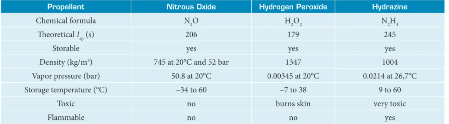
conditions in about 50.8 bar at 20°C. A comparison of nitrous oxide with other monopropellants is shown in Table 1.
Nitrous oxide starts decomposition between 520°C to 850°C, forming mostly nitrogen (N2) and oxygen (O2), and releasing heat. Due to the high amount of energy needed to initiate the decomposition, catalysts are used to reduce the activation energy of the reaction, then yielding a lower decomposition temperature, around 250°C. However, the system must be preheated to this temperature to start the exothermic decomposition and attain a self-sustaining reaction. Reaching this condition, the adiabatic decomposition temperature is around 1640°C, producing a theoretical speciic impulse of 206 s (Zakirov et al., 2001).
NITROUS OXIDE DECOMPOSITION
he chemical mechanism of the gas phase decomposition of nitrous oxide starts with:
(1)
where M is a third body (Karabeyoglu et al., 2008). he O radical reacts with N2O according to the two parallel reactions:
(2)
(3)
The O radical can be eliminated by a termolecular homogeneous recombination:
(4)
or by a heterogeneous recombination:
(5)
Secondary reactions involved mainly in the formation of NO are:
(6)
(7)
(8)
(9)
The previous equations can be combined, yielding the following global reactions:
(10)
(11)
he reaction involving N2/O2 is exothermic and the NO/N2 reaction is endothermic.
Catalytic reactions ofer advantages since they favor the N2/O2 self-sustaining reaction and improve the reaction eiciency (Wilson et al., 2012; Lohner et al., 2007; Zakirov and Zhang, 2008). he catalytic decomposition of nitrous oxide starts
Propellant Nitrous Oxide Hydrogen Peroxide Hydrazine
Chemical formula N2O H2O2 N2H4
heoretical Isp (s) 206 179 245
Storable yes yes yes
Density (kg/m3) 745 at 20°C and 52 bar 1347 1004
Vapor pressure (bar) 50.8 at 20°C 0.00345 at 20°C 0.0214 at 26,7°C
Storage temperature (°C) –34 to 60 –7 to 38 9 to 60
Toxic no burns skin very toxic
Flammable no no yes
Table 1. Comparison of nitrous oxide with others monopropellants (Zakirov et al., 2001).
I
with the adsortion of a N2O molecule in an active site on the catalyst surface. Ater that, the N2 molecule is released while the oxygen atom remains adsorved on the active site. At last, the oxygen atom is released when it combines with another oxygen atom in a nearby active site, forming O2 or by direct reaction with another N2O molecule. hese steps are described by:
(12)
(13)
(14)
(15)
In reactions (12-15) the O-M term refers to an oxygen radical and the N2O-M term refers to a N2O molecule adsorved on the catalyst surface. The []-M term corresponds
to an empty site on the catalyst surface. During N2O
decomposition, the adsortion of oxygen radicals coming from the catalytic surface is often considered a limiting factor. For this reason, the decomposition rate of N2O is intimately linked to the bind energy between the catalyst metal and the oxygen atom (Scherson and Lohner, 2009; Kapteijn et al., 1996).
CATALYST FOR N
2O DECOMPOSITION
A catalyst is used to provide a rapid propellant decomposition, without changing the global reaction. The reactants bind chemically to the surface of the catalyst active sites, which are atoms or groups of atoms available for reaction. When the catalyst is solid, the active material is composed of metal or metal oxides which are dispersed over a high surface area material, increasing the contact area between reactants and active sites (Batta et al., 1962; Vieira et al., 2003). In the case of gaseous nitrous oxide, this is obtained by making it pass through a material with transition metals, such as Ir, Rh, Ru, Ni, Co, Cu or Zr.
here are several characteristics which afect the catalyst performance. he most important one is the decomposition limiting factor. he reaction can be controlled by diferent processes:
• Chemical kinetics, limited by the speed of N2O adsorption on the catalyst, that is, the speed of combination of N2O with a rhodium molecule in an active site and release of oxygen and nitrogen;
• Difusion in the catalyst pores, where the reaction is limited by difusion of reactants and products into and out of these microscopic pores; and
• Convection in the difusion boundary layer around each pellet catalyst, which cannot carry the products and reactants from the surface.
Knowing which of these modes is important will determine how the catalyst bed should be sized (Figueiredo and Ribeiro, 1989).
Tests are needed also to determine the critical temperature range. It is necessary to know when the decomposition reaction changes from slow to fast and complete. he catalyst must be tested to determine the maximum temperature at which it can be used without deterioration of its properties. his should be checked since the active material (Rh, Ru, Ir) to be deposited on the support material surface also will be subjected to high temperatures. Placing these active elements at very high temperatures can cause their vaporization and removal of the support surface, destroying the catalyst (Figueiredo and Ribeiro, 1989).
Being commercially available and having a relatively low cost, supports based on alumina (Al2O3) are widely used for catalytic purposes in propulsion. The aluminum oxide is formed at room temperature in γ-Al2O3 phase and has an open structure consisting of amorphous aggregates of Al12O18. When the temperature increases (around 1200°C) aluminum oxide goes through diferent phases irreversibly to form α-Al2O3 which is the inal stage of its internal structure. Although the stages of transition are not well understood, it is well known that for each transition, the available surface area per gram of oxide decreases signiicantly, causing a decrease in the number of active sites available for decomposition (Arai and Machida, 1996; Vafai, 2005).
THRUSTER DESIGN
he thruster design was based on a performance theoretical study carried out with aid of CEA2 NASA (2012) program. his program initially determines the chemical equilibrium composition and temperature in the chamber for constant pressure and enthalpy, through minimization of the Gibbs free energy. hen it solves the conservation equations for one-dimensional isentropic steady low along the nozzle considering equilibrium or frozen conditions. As input parameters, the properties of pure nitrous oxide gas were considered at a temperature of 298.16 K, atmospheric pressure of 0.95 bar, 5 bar pressure in the chamber and assuming frozen low in the nozzle. Data obtained with the NASA CEA2 code are shown in Tables 2 and 3. Table 3 conirms that the main decomposition products are O2 and N2. Table 4 shows some dimensions of the nozzle and the mass low rate of propellant calculated to yield 2 N thrust.
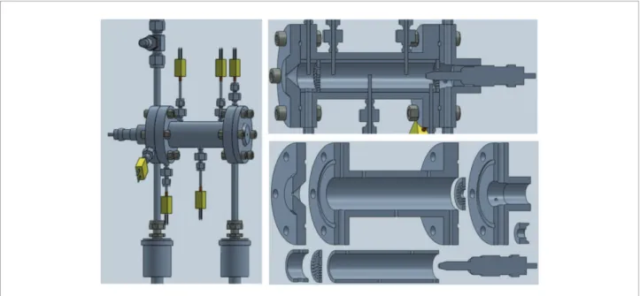
Estimates of the length and diameter of the catalytic chamber were made based on the literature of monopropellant catalytic thrusters (Lohner et al., 2007; Scherson and Lohner, 2009; Cai et al., 2011). hus, the reference values adopted for initial design of the catalyst chamber were 15 mm in diameter and 70 mm in length (D15L70). All thruster parts (lange injection, chamber, catalyst bed and nozzle) were manufactured in 316 stainless steel. Computational views of thruster (3D drawings) are shown in Fig. 2, whereas Fig. 3a depicts the disassembled thruster and Fig. 3b, thruster mounted in the thrust balance.
TEST BENCH
A test bench was used to determine thrust, mass low rate, temperatures and pressures in the supply line and in the thruster. A schematic of the test bench is showed in Fig. 4. It contains
Thruster parameters
Thruster chamber
Nozzle throat
Nozzle exhaustion
P (bar) 5.0000 2.7262 0.9505
T (K) 1906.92 1658.40 1293.97
ρ (kg/m3) 0.92529 0.58010 0.25924
cp (kJ/kg/K) 1.2403 1.2213 1.1842
γ 1.2961 1.3021 1.3146
Mach 0.000 1.000 1.758
Ae/Ag - 1.000 1.4343
c* (m/s) - 1101.8 1101.8
CF - 0.7099 1.1076
Ivac (m/s) - 1383.0 1520.9
Isp (m/s) - 782.2 1220.4
P = chamber pressure; T = chamber temperature; ρ = density of products;
c
p = speciic heat of the products; γ = ratio of speciic heats of products;
Mach = Mach number; A
e = exhaustion area; Ag = throat area;
c* = characteristic velocity; C
F = coeficient of thrust;
I
vac = speciic impulse in vacuum; Isp= speciic impulse with adapted nozzle. Table 2. Thruster theoretical parameters.
Table 3. N2O decomposition products.
Products Molar fractions
NO 0.06370
O 0.00008
NO2 0.00004
O2 0.32988
N2 0.66327
Parameters Values
Ag (mm2) 3.61
Dg (mm) 2.14
Ae (mm2) 5.17
De (mm) 2.56
m. (/s) 1.63
Table 4. Thruster parameters and dimensions.
Figure 2. 3D drawings of the thruster with instrumentation and cut views.
Figure 3. Thruster photos.
Control valve
Thermocouples
Pressure transducer Ppc
Thruster with thermal insultation
Pressure transducer Pinj
Load cell Power supply Nitrous oxide
bottle Pressure regulator with heather
Line pressure gauge
Filter Shut-off valve Flow
meter Flow
valve
Check valve Bypass
valve T4
T3 T1 Tpc
T2 Tinj
Figure 4. Test bench scheme.
a gas cylinder with nitrous oxide (99.99%), a heated pressure regulator, sintered ilters in the gas inlet valves, manual lock valves, two-way solenoid valve with direct action, check valve, pressure transmitters, K-type thermocouples, HBM load cell with 5 N capacity (± 0.01 N), and a Sevenstar nitrous oxidizer mass flow meter. Preheating of the nitrous oxide to start decomposition was performed by a Duratherm Bosch glow-plug placed at the entrance of the catalyst bed, as depicted in Fig. 2. he injection temperature, i.e., the gaseous nitrous oxide temperature at the entrance of the catalyst bed, was adjusted by a temperature controller (Novus 480I) which monitored the glow-plug heating.
A data control system using a National Instruments SC-2345 rack, TCC02 modules (for signals in mV), FT01 modules (with channels 0-10 V), Compact Daq USB module (extra channels of analog inputs and communication module) and a PCI-6221 data acquisition board were used for observations of the experiments variables in real time. A Labview control software monitored variables of pressure, mass flow rate, thrust, temperature and operation of the glow-plug. For this purpose, analog and digital input/output were used, providing data on a computer in graphical form and saving in its database.
RESULTS AND DISCUSSION
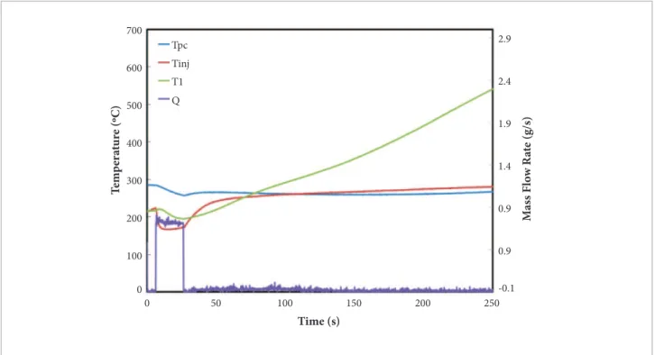
A pressure of 7.5 bar at the exit of the regulator valve was adopted to provide the total pressure drop on the various devices installed before the thruster. Once the temperature (thermocouple Tinj) measured in the glow-plug heater section reached 220°C the injection of nitrous oxide was performed. This is evidenced in Fig. 5 which shows that a pulse with a mass flow rate (Q) of 1.6 g/s increased rapidly the catalytic bed temperature, thus indicating the occurrence of catalytic decomposition.
Locations of Tinj, T1, T2, T3 and T4 thermocouples along the catalytic chamber can be seen in Figs. 2 and 4. Tpc is the measured temperature ater the catalytic bed (post-chamber). Prior to testing, pre-heating was kept for several minutes for thermal stabilization of the catalyst bed.
Ater the preheating period, the glow plug temperature controller was turned of. he mass low rate was gradually increased to the nominal low rate and heating was maintained only by the decomposition of N2O low. Under these conditions, it was possible to apply multiple sequences of pulses with diferent duty cycles, i.e., periods with mass low on and of. Very long shots could compromise the thruster and thermocouples, due to
Figure 5. Initial heating using N2O. 700
2.9
Tpc
Tinj T1
Q
2.4
1.9
1.4
0.9
0.9
-0.1 600
500
400
300
200
100
T
em
p
er
at
ur
e (ºC)
Time (s)
M
ass F
lo
w R
at
e (g/s)
0
the high temperatures that could be reached in the bed. During intervals, there occurred a temperature uniformization along the thruster, especially in the catalytic bed.
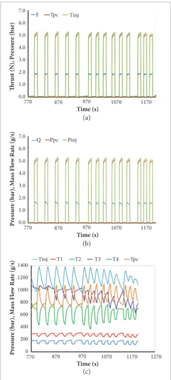
Figure 6 shows curves of pressures, temperatures and mass low rates measured in the thrust balance. A sequence of 5 pulses with 25 s on and 10 s of is shown, followed by sequences of 3
pulses with 15 s on and 10 s of. It is observed that the injection pressures (Pinj) and post-chamber (Ppc) reached 5.29 bar and 5.15 bar, respectively. he temperature at the end of the catalytic bed (T4) reached 1400°C with an average mass low rate (Q) of 1.65 g/s. he thrust (F) measured on the load cell reached 1.93 N, close to the design value of 2 N.
Figure 7 shows the gas temperature evolution inside the catalytic chamber of the thruster. A MATLAB algorithm using a cubic interpolation method was developed to determine the temperature distributions during the thermal-catalytic decomposition process.
Taking as reference the pulse in the interval of 860 s to 900 s in Fig. 6c, it was observed that the highest temperature (1400°C) was measured by the thermocouple located at 62 mm from the injection, as shown in Figs. 2 and 4. his corresponds to the last catalytic bed thermocouple (T4). he maximum temperature reached at the end of the catalytic chamber indicates a bed with optimum length. he hot expanding gases from decomposition pass through the post-chamber and follow to the nozzle for generating thrust.
Pulses present similar proiles for several sequences and in diferent periods. However, the fatigue of the catalyst can be observed in the range of 1136 s to 1200 s in Fig. 6, where pulses are deliberately shown with a decrease in catalyst eiciency. his is due to the pellet contraction and loss of rhodium oxide. he contraction of the pellets is caused by the low calcination temperatures and phase change of alumina, as was previously described by Arai and Machida (1996). he rhodium oxide loss is due to the high temperatures reached in the catalytic bed. he decrease in pellet volume also creates preferential paths for N2O low which pass through the catalytic bed without decomposition. Besides, it causes a decrease in the catalyst speciic area, reducing the area of active sites available for catalytic reaction. If the surface available for decomposition is internal to the pellets, with the alumina retraction the active sites become inaccessible for N2O, preventing its decomposition. However, there was no clustering of catalyst grains or weight loss.
here is also a loss of eiciency concerning the reduction of the adsorption capacity of the molecules of N2O, as seen in the last three pulses in Figs. 6, 8 and 9. his may be explained by the adsortion of water and oxygen which reduces the number of active sites available for N2O decomposition (Esclapez, 2011). his factor, jointly with the retraction of alumina and heat losses, can decrease the reaction temperature in
7.0
Tpc Tinj F
6.0
5.0
4.0
3.0
2.0
1.0
Thr
us
t (N), P
ress
ur
e (b
ar)
Time (s) 0.0
770 870 970 1070 1170
7.0
Ppc Pinj Q
6.0
5.0
4.0
3.0
2.0
1.0
P
ress
ur
e (b
ar), M
ass F
lo
w R
at
e (g/s)
Time (s) 0.0
770 870 970 1070 1170
1400
Tpc
Tinj T1 T2 T3 T4
1200
1000
800
600
400
200
P
ress
ur
e (b
ar), M
ass F
lo
w R
at
e (g/s)
Time (s) 0
770 870 970 1070 1170 1270
Figure 6. D15L70 thruster duty cycle testing.
(a)
(b)
the bed. It should be noted that using shorter pulse lengths would provide lower temperatures and a slower degradation of the catalyst.
Figure 8 shows the speciic impulse, , and the
characteristic velocity, , obtained experimentally.
he pulses shown in Fig. 6 were taken as reference, since they were obtained with the thruster in full operation at the start of degradation of the catalyst.
The average specific impulse obtained experimentally was about 1120 m/s, which is close to the theoretical value, 1220.4 m/s. herefore, the average speciic impulse eiciency, , was around 91.7 %. he characteristic
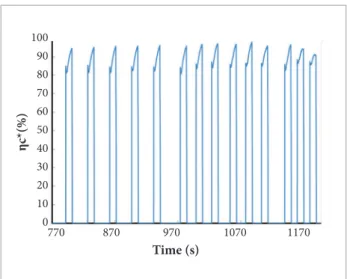
velocity efficiency, , is shown in Fig. 9.
he characteristic velocity value obtained in the experiments was about 970 m/s, whereas the average theoretical value is about 1102 m/s, giving an average eiciency of about 88%. Considering the characteristic velocity eiciency obtained experimentally, it is observed that the catalytic decomposition of nitrous oxide in the bed was not complete.
CONCLUSIONS
An experimental investigation of a monopropellant 2 N thermal-catalytic prototype thruster using gaseous nitrous oxide was presented. he propellant was decomposed by a catalyst of rhodium oxide supported on alumina, with pre-heating of both catalyst and propellant by a glow-plug system.
1200
1000
800
600
400
200
0
S
p
e
cifi
c I
m
p
u
ls
e (m/s)
Time (s)
770 870 970 1070 1170
1200
800
600
400
200
0
C
ha
rac
te
ris
ti
c V
el
o
ci
ty (ms)
Time (s)
770 870 970 1070 1170
Figure 8. Speciic impulse (a) and characteristic velocitie(b).
895
890
885
880
875
870
865
T
im
e (s)
Position (mm)
10 20 30 40 50 60 70
1300
1200
1100
1000
900
800
700
600
500
400
300
Figure 7. Gas temperature (°C) evolution along the catalytic bed and post-chamber section.
100 90 80 70 60 50 40 30 20 10 0
η
c*
(%
)
Time (s)
770 870 970 1070 1170
Figure 9. Characteristic velocity eficiency.
(a)
Relatively high decomposition eiciency (~ 88 %) was observed prior to catalyst degradation. Changes in the catalytic support preparation are required to reduce the volume loss of the support under the test conditions and to improve catalyst performance for longer iring times. Other factors such as optimization of catalytic bed dimensions, improvements in the injector design and better thermal insulation may increase the thruster’s eiciency.
ACKNOWLEDGEMENTS
he authors acknowledge the Brazilian Conselho Nacional de
Desenvolvimento Cientíico e Tecnológico (CNPq) for providing
a doctoral scholarship to the irst author and a research grant to the second one. he catalyst preparation was performed with the kind help of Dr. Ricardo Vieira from Brazilian Instituto
Nacional de Pesquisas Espaciais (INPE).
REFERENCES
Amaral, L., 1995, “Química”, Loyola, São Paulo, 23-24.
Arai, H. and Machida, M., 1996, “Thermal stabilization of catalyst supports and their application to High Temperature catalytic combustion”. Applied Catalysis A: General, Vol. 138, No. 2, pp. 161-176. doi: 10.1016/0926-860X(95)00294-4.
Batta, I., Solymost, F. and Szabo, Z., 1962, “Decomposition of nitrous oxide on some doped cupric oxide catalysts”. Journal of Catalysis, Vol. 1, No. 2, pp. 103-112. doi: 10.1016/0021-9517(62)90014-3.
Brown, C.D., 1995, “Spacecraft Propulsion”. Ohio: Series Editor-in-Chief. AAIA Education Series. Air Force Institute Technology, pp. 224.
Cai, G., Sun, W., Fang, J., Li, M., Cong,Y. and Yang, Z., 2011, “Design and performance characterization of a sub-Newton N2O monopropellant Thruster”. Aerospace Science and Technology, Vol. 23, No. 1, pp. 439-451. doi: 10.1016/j.ast.2011.10.003.
Esclapez, S.P., 2011, “N2O Decomposition rhodium/ceria catalysts: From principles to pratical application”, PhD Thesis, Inorganic Chemistry Department, Alicante University, Spain, pp. 201.
Figueiredo, J.L. and Ribeiro, F.R., 1989, “Catálise Heterogênea”. Calouste Gulbenkian Foundation, Porto, Portugal, pp. 353.
Junior, J.A., 2009, “Desenvolvimento de um Propulsor Catalítico para Satélites usando Óxido Nitroso como Propelente”, Master Thesis, Instituto Nacional de Pesquisas Espaciais - INPE, Cachoeira Paulista, Brazil, pp. 168.
Humble, R.W., Henry, G.N. and Larson, W.J., 1995, “Space Propulsion Analysis and Designer”.MacGraw-Hill Companies, Inc., Primis Custom Publishing.
Kapteijn, F., Mirasol, J.R. and Moulijn, J.A., 1996, “Review: Heterogeneous catalytic decomposition of nitrous oxide”. Applied Catalysis B: Environmental 9, pp. 25-64. doi: 10.1016/0926-3373(96)90072-7.
Karabeyoglu, A., Dyer, J., Stevens, J. and Cantwell, B., 2008, “Modeling of N2O Decomposition Events”. American Institute of Aeronautics and Astronautics, 44th AIAA/ASME/SAE/ASEE Joint Propulsion Conference & Exhibit, Hartford.
Lohner, K., Dyer, J., Doran, E., Dunn, Z., Krieger, B., Decker, V., Wooley, E., Sadhwani, A., Cantwell, B. and Kenny, T., 2007, “Design and Development of a Sub-Scale Nitrous Oxide Monopropellant Gas Generator”, American Institute of Aeronautics and Astronautics, Stanford University, Stanford, USA.
Makled, A.E. and Belal, H., 2009, “Modeling of Hydrazine Decomposition for Monopropellant Thrusters”. 13th International Conference on Aerospace Sciences & Aviation Technology, ASAT - 13, Military Technical College, Kobry Elkobbah, Cairo, Egypt.
Merril, C., 2008, “Nitrous Oxide Explosive Hazards”, Air Force Research Laboratory, Edwards AFB, CA.
NASA, “Chemical Equilibrium with Applications (CEA)”. Cleveland, OH: Glenn Research. Center NASA, Retrieved on March 5, 2012, from http://www.grc.nasa.gov/WWW/CEAWeb/ceaguiDownloadwin. htm.
Neto, T.G.S., 2011, “Handout catalysis”. Instituto Nacional de Pesquisas Espaciais, Curso de Engenharia e Tecnologias Espaciais.
Plumlee, D. and Steciak, J., 2004, “Development of a monopropellant micro-nozzle and Ion Mobility spectrometer in LTCC”, In: Ceramic Interconnect Technology Workshop, Denver, CO.
Scherson, Y. and Lohner, K., 2009, “A Monopropellant Gas Generator Based on N2O Decomposition for “Green” Propulsion and Power Applications”. American Institute of Aeronautics and Astronautics, 45th AIAA/ASME/ SAE/ASEE Joint Propulsion Conference & Exhibit, Denver, Colorado, EUA.
Sanscrainte, W., 1961, “Hydrogen Peroxide Attitude Control Systems”. Planetary and Space Science, Vol. 4, pp. 184-193. doi: 10.1016/0032-0633(61)90131-3.
Stark, J.P.W.J. and Swinerd, G.G., 2003, “Mission Analysis”, In: Fortescue, P., Stark, J. and Swinerd, G., (Eds.), Spacecraft Systems Engineering, 3rd ed., John Wiley & Sons, pp 111-167.
Sutton, G.P., 2001, “Rocket propulsion elements: an introduction to the engineering of rockets”. 7. ed. John Wiley & Sons, pp. 751.
Vafai, K., 2005, “Handbook of Porous Media”. 2nd Edition. Taylor & Francis Group, LLC, London, UK, pp. 742.
Vieira, R., Cuong, P., Keller, N. and Ledoux, M.J., “Novos Materiais à base de Nanoibras de Carbono como Suporte de Catalisador na Decomposição da Hidrazina”. Química Nova, Vol. 26, No. 5, pp. 665-669. doi: 10.1590/S0100-40422003000500008.
Wilson, M.D., Eilers, S.D. and Whitmore, S.A., 2012, “Catalytic Decomposition of Nitrous Oxide Monopropellant for Hybrid Motor Re-Ignition”. American Institute of Aeronautics and Astronautics, 48th AIAA/ASME/SAE/ ASEE Joint Propulsion Conference & Exhibit, Atlanta, Georgia, USA.
Zakirov, A.V. and Zhang, H., 2008, “A model for the operation of nitrous oxide monopropellant”. Aerospace Science and Technology, Vol. 12, No. 4, pp.318-323. doi: 10.1016/j.ast.2007.08.003.
Zakirov, V., Sweeting, M., Goeman, V. and Lawrence, T., 2000, “Surrey research on nitrous oxide catalytic decomposition for space applications”. 14th AIAAUSU Conference on Small Satellites, pp. 1–9.
Zakirov, V. and Li, L., 2004, “Small Satellite Propulsion Challenges”. European Conference for Aerospace Sciences (EUCASS), Tsinghua University, P.R. China.