Abstract
In this paper, the effect of ductile damage on the behavior of a dented Aluminum pipe subjected to internal pressure is investiga-ted. The plastic behavior of pipes under indentation is studied using continuum damage mechanics theory and the elastic-plastic finite element analysis. Finite element calculations are carried out using the damage plasticity model proposed by Xue and Wierzbi-cki. The proposed damage plasticity model incorporates effects of both hydrostatic stress and the Lode angle to define the fracture envelope. Numerical calculations for different ranges of internal pressures and indenter diameters with and without damage effect are carried out and results are compared. It is shown that damage has a significant effect on the load bearing capacity of an indented pipe. Results of the present study confirm the credibility of the proposed model in predicting the ductile fracture under multi-axial state of stress loadings.
Keywords
Ductile damage, Indentation, Plasticity, Finite element analyses, Load bearing capacity.
Load Bearing Capacity of a Dented Aluminum Pipe Subjected
to Internal Pressure Considering the Effect of Ductile Damage
1 INTRODUCTION
Pipelines are widely used for transmission of gases and liquids from production sites to end users with a reasonably good safety record which is mainly due to appropriate design process, material selection and operating practices (Hyde et al. 2005). One of the most common causes of failures in onshore and offshore structures, oil and gas transmission pipelines is dent. A dent in a pipeline is considered as a permanent plastic deformation of the cross-section of the pipe that causes a local stress and strain concentration and a reduction in the pipe diameter (Cosham and Hapkins,
R. Akbari Alashti 1a S. Jafari 2b
S.J. Hosseinipour 3c
a Mechanical Engineering Department, Babol
University of Technology, P.O. Box 484, Babol, Mazandaran, Iran, [email protected] b Mechanical Engineering Department, Babol
University of Technology, P.O. Box 484, Babol, Mazandaran, Iran,
c Mechanical Engineering Department, Babol
University of Technology, P.O. Box 484, Babol, Mazandaran, Iran.
http://dx.doi.org/10.1590/1679-78251383
Latin A m erican Journal of Solids and Structures 12 (2015) 355-384
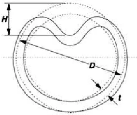
2004). The depth of the dent is defined as the maximum reduction in the diameter of the pipe in comparison with the original diameter as shown in Figure 1. There are different types of pipeline dents which are defined according to their degrees of impact on the pipeline wall dimensions and geometries (Alexander, 1999, Allouti et al, 2012).
Figure 1: Dimensions of a dented pipe.
Previous research works on dented pipes were mostly concentrated on the experimental and finite element calculations rather than the analytical evaluations. Furthermore, to the knowledge of authors no research work has been presented on the finite element calculation of limit loads of indented pipes considering the effect of ductile fracture models. Cosham et al. (2004) worked on effects of various types of dents including plain dents, dents on welds and dents containing de-fects on the static and cyclic strength of a pipe. They have shown that a dent reduces the static and cyclic strength of the pipe. The collapse of mild steel pipes with different outside diameter to wall thickness ratios containing plain or gouged dents under the effect of internal pressure and bending moment was studied numerically and experimentally by Blachut et al. (2007, 2008). They also provided details about 40 tests on pipes having dents with longitudinal gouges, with and without internal pressure loading (Blachut et al, 2007). The finite element results have shown that in case of a hemispherical indenter, there was no full contact between the indenter and the pipe (Blachut et al, 2007, 2008). Also, the collapse of a dented stainless steel pipe under the effect of an external pressure loading was investigated experimentally by Park et al. (1996).
Latin A m erican Journal of Solids and Structures 12 (2015) 355-384 The influence of the dent depth on the burst pressure of a pipeline was evaluated using finite
element and experimental methods with simple local strain criterion named as the Oyane s
crite-rion (Allouti et al, 2012). It was found that as the pressure increases, the Oyane s critecrite-rion reach-es to an asymptotic value that is lreach-ess than the critical value. In the recent work reported by Baek et al. (2012), a finite element analysis was carried out on the load bearing capacity of API X65 pipe with dent defect under internal pressure and in-plane bending without considering the dam-age effect. Allouti et al. (2014) worked on A37 steel pipelines containing a gouge and dent defect and investigated the influence of the dent depth on the burst pressure of these pipelines. Also, the impact by dropped objects on an internally pressurized pipeline resting on a flexible bed has been numerically simulated by Zeinoddini et al. (2013) without considering damage effect.
Two approaches are often used in the study of mechanical behavior of engineering materials. Macroscopically, degradation of the material exhibits a decrease of the material stiffness and strength and a reduction of the remaining ductility (Lemaitre, 1992, Xue, 2007). Microscopically, damage is mainly due to void nucleation, growth and coalescence, shear band movement and the propagation of micro-cracks (McClintock, 1968, Rice and Tracey, 1969, Xue, 2007). Hydrostatic tension speeds up both these activities while compressive pressure slows down such action in which the fracture is more often governed by shear failure. Low positive stress triaxialities are combinations of both mechanisms acting on the micro-scale (Xue, 2007, Brünig et al, 2014). Ex-perimental work shows that compressive pressure increases the ductility in many ductile and brit-tle materials. The damage associated with the void shearing effect was recently introduced to the Gurson-type model so that ductile fracture at low stress triaxiality can be predicted (Xue, 2008, Hutchinson et al, 2008).
Accumulation of damage, initiation of fracture as a result of the accumulation of the ductile damage and the crack propagation are the three phases of ductile failure of structures (Lemaitre, 1985, Xue, 2007). Ductile fracture refers to fractures where materials experience large plastic de-formation and exhibit high ductility in the concerned region (Xue, 2007, Xue et al, 2007-2010). For small and moderate plasticity, the damage effect on the matrix strength curve is negligible and the material strength curve may be considered to be equal to that proposed by the classical continuum mechanics. However, in case of large plastic deformations such as pipes under indenta-tion, the damage effect must be considered in prediction of material deterioration for modified stress-strain curve (Xue, 2007, Xue et al, 2007-2010).
cu-Latin A m erican Journal of Solids and Structures 12 (2015) 355-384
mulative-strain-damage fracture method, the damage is associated with the plastic deformation and always leads to material softening. The damage is defined using an integral of the weighting function with respect to the equivalent plastic strain and further incorporating the damage into the yield condition. When the accumulated damage exceeds a threshold value, the material is considered to fail (Wilkins et al, 1980, Xue, 2007). This is the foundation of the conventional continuum mechanic models (CCM) and a later extension of this line of damage model is the continuum damage mechanic model (CDM).
In CCM models, the microstructure of the material is assumed to remain unchanged and the damage is treated as a function of the accumulated equivalent plastic strain, independent of the material strength such as in Wilkins et al. (1980) and conventional Johnson and Cook (1985). In CDM models material property is defined by the combined effect of the matrix material and the damage to account for the micro defects such as the one proposed by Lemaitre (1985) and Xue and Wierzbicki (X-W) (2007). So, the yielding is a function of the current state of damage in addition to the plastic strain. In some models, a critical value of damage is proposed as a material constant which is to be calibrated, such as in Wilkins et al. (1980) and Lemaitre (1985), while in other models the fracture criteria are normalized with respect to the critical values such as con-ventional and improved Johnson and Cook (1985, Borvik et al, 2001) and finally in the model proposed by Xue (2007) the fracture occurs when the damage reaches the unity.
By reviewing the research works carried out in the field of ductile fracture models, one can find that the most challenging issue is to offer a better model for prediction of fracture in the corresponding stress state (Wilkins et al, 1980, Lemaitre, 1985, Johnson and Cook, 1985, Xue, 2007, Bai et al, 2010, Mohr et al 2011, Brünig et al, 2014). To achieve this, specific combinations of parameters with different mathematical forms are introduced in each fracture model. In most fracture models, the fracture strain envelope is defined in such way that the influence of stress state on the fracture prediction is satisfied. Generally fracture envelopes are defined by appropri-ate combination of pressure and Lode angle function (Wilkins et al, 1980, Xue, 2007). Moreover, the pressure effect on the fracture strain can be described by the stress triaxiality ratio such as the ones proposed by Lemaitre (1985), conventional and improved Johnson-Cook (1985, Borvik et
al, 2001), modified Mohr–Coulomb model (2010). However, in Wilkins et al (1980), (X-W) (2007,
2010) and Norris et al (1978) the pressure effect is presented by the hydrostatic pressure only. The hydrostatic pressure (the first stress invariant) and the Lode angle parameter (the third de-viatoric stress invariant) have significant effects on the shape of the fracture envelop in the prin-cipal stress space and are generally defined based on the three prinprin-cipal stresses and three princi-pal deviatoric stresses.
Latin A m erican Journal of Solids and Structures 12 (2015) 355-384 damage accumulated along the corresponding loading path (Xue, 2007, Xue et al, 2007-2010). The softening effect becomes one of the most important parameter when a ductile material is subject-ed to large plastic deformation. As the plastic deformation increases, micro cracks are initiatsubject-ed and propagated, hence the softening effect must be considered using an appropriate weakening function in the ductile fracture model (Xue, 2007, Xue et al, 2007-2010). The Lode angle parame-ter modifies the cross section of the fracture envelop on the octahedral plane based on the current deviatoric stress state of the material. The hydrostatic pressure parameter is important and in each step of the loading process the shape of fracture envelope is improved by the hydrostatic pressure parameter.
Mohr et al. (2008) presented a new experimental technique that can be used to investigate the large deformation behavior of advanced high strength steel sheets. Later they used this tech-nique and studied experimentally and numerically the stress and strain histories at the point of fracture initiation in steel sheets tensile specimens with central holes and circular notches (Mohr et al, 2010). They showed that both the equivalent plastic strain and the stress triaxiality are very sensitive to uncertainties in experimental measurements and numerical model assumptions. Mohr et al. (2011) used results of these fracture experiments to calibrate and validate
shear-modified Gurson model and Modified Mohr–Coulomb model. Bai and Wierzbicki (2010)
trans-ferred the classical Mohr–Coulomb (M–C) fracture criterion in to the space of stress triaxiallity,
Lode angle and equivalent plastic strain, defining the so-called modified Mohr–Coulomb (MMC)
fracture criterion. The MMC model is based on the assumption that the initiation of fracture is determined by a critical stress state. In MMC model, the Lode angle dependence is close to the parabolic form and the number of material constants must be calibrated is high (Mohr et al, 2011).
Recently Brünig et al. (2014) also worked on another stress-state-dependent ductile fracture model. Series of new experiments and corresponding numerical simulations were used to model material behavior by continuum plasticity and continuum damage model based on free energy functions. The model developed by Brünig et al. (2014) is constructed on the basis of three pa-rameters namely, the stress intensity, the stress triaxiality and the Lode parameter. Several three-dimensional micro-mechanical numerical analyses are performed for covering a wide range of stress triaxialities and Lode parameters in tension, shear and compression domains (Brünig et al, 2013). Also the effect of stress triaxiality on the inelastic deformation behavior of aluminum al-loys for smooth and pre-notched tensile and shear specimens were studied experimentally and numerically by Brünig et al (2011).
Latin A m erican Journal of Solids and Structures 12 (2015) 355-384
CDM theory. In CDM theory, material deterioration is described by an internal variable known as damage. Plastic deformation that contributes to damage is calculated by integrating the dam-age rate measured at current loading. A power law damdam-age rule is proposed to characterize the nonlinearity in damage accumulation. The damage related weakening factor is adopted to de-scribe the material deterioration. The material and damage parameters are obtained from stand-ard laboratory tests reported in (Xue, 2007) for Aluminum 2024-T351 alloy. The pipe is dented with a rigid, spherical indenter with different diameters i.e. 40, 80 and 160mm. The diameter and wall thickness of the pipe are assumed to be 762 mm and 17.5 mm, respectively. Pipes are as-sumed to be subjected to an atmospheric pressure as well as 4, 8, and 16MPa internal pressure. The results for finite element simulations with and without damage effect are obtained and com-pared.
2 DAMAGE PLASTICITY MODEL
2.1 Formulation of X-W Damage Plasticity Model
The results of experiments carried out on the behavior of ductile materials reveals that for better prediction of material behavior along the loading path, an appropriate damage model must be included to the classical plasticity theory (Xue, 2007, Xue et al, 2007-2010). (X-W) ductile frac-ture model is a combination of the appropriate damage model with the classical plasticity theory.
The damage is assumed to be isotropic and quantified by the scalar parameter,D. In order to
define the nonlinearity of the damage accumulation, a power law damage rule is supposed. In the
principal stress space, the hydrostatic pressure (
p
), von Mises equivalent stress (
eq) and theLode angle parameter (
θ
L) are defined in terms of
1,
2,
3, i.e. the maximum, intermediateand minimum principal stresses and
s
1,s
2,s
3, i.e. the maximum, intermediate and minimumprincipal deviatoric stresses as follow (Xue, 2007, Xue et al, 2007-2010):
1 2 3
1
( )
3
p
(1)
2
2 21 2 1 3 2 3
1
( )
2
eq
(2)
1 2 3
L
1 3
S
S
1
θ
tan
β
1
S
S
3
(3)
In (X-W) model, ductile damage parameterDis used to define the fracture criterion by setting
the inequality
D
D
cr, whereD
cris the material constant. The fracture criterion is generallyex-pressed in the non dimensional form of
(
D D
/
cr)
1
(Xue, 2007). It is assumed thatD
0
, for theLatin A m erican Journal of Solids and Structures 12 (2015) 355-384 (Xue, 2007, Xue et al, 2007-2010). In general, for an arbitrary plastic loading path, the damage is obtained by the following integral:
0
1
c
D dD
(4)where
cis the critical strain at which fracture occurs.2.2 Damage Rule
The power law function of the damage rule of the following form is considered in (X-W) damage plasticity model (Xue, 2007):
mp eq f
D
(5)where p
eq
is the accumulated equivalent plastic strain. For a known,
f , the incremental damageevolution law for numerical implementation can be derived as:
1 m
p p
eq eq
f f
d
dD
m
(6)
wherem is the material parameter,
f is the effective fracture strain envelope defined on thestress state in the next sections (Xue, 2007).
2.3 The Softening Effect
When the damage occurs, the material strength is decreased due to the reduction of the effective load carrying area (Xue, 2007, Xue et al, 2007-2010). This effect can be modeled with the materi-al weakening due to the plastic damage that is incorporated as a scmateri-alar function to the matrix strength. On the basis of the CDM theory, the constitutive equation of the damaged material can be derived from the modified yield potential function:
( )
eq
w D
M
(7)We include a particular form of the weakening effect by the weakening factor of
(1
D
)
, i.e.(1
)
eq D M
(8)whereMis the matrix strength and
is the weakening factor that is assumed to be aLatin A m erican Journal of Solids and Structures 12 (2015) 355-384
2.4 Cylindrical decomposition of damage
In the cylindrical decomposition method, the pressure sensitivity and the Lode angle dependence
of the fracture strains are included by the pressure dependence function
p( )
p
and the Lode angledependence function,
( )
, respectively (Xue, 2007, Xue et al, 2007-2010). It is supposed thatthe pressure sensitivity and the Lode angle dependency on the fracture strain are independent of each other and the fracture strain envelope obtained by multiplication of the pressure sensitivity and the Lode dependency function is assumed to take the following form:
0
( )
f f p
p
(9)where
f0is the reference fracture strain in the uniaxial tension state without confining pressure.The uniaxial tension tests under confining pressure for different alloys were carried out by Bridgman. The relation between the fracture strain and the confining pressure were presented in his work (Bridgman, 1952).The pressure dependence function for the (X-W) damage plasticity model is the result of the Bridgman uniaxial tension tests under pressure loading. In the present study, a logarithmic form of the pressure dependence function is defined as follow (Xue, 2007):
lim
lim
(1
1
/
),
[1 exp 1/
]
0
[1 exp 1/
]
Lim p
q Ln p p p p q
p p q
p
(10)
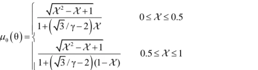
The Lode angle dependence function in (X-W) model is a result of its definition in Wilikins et al.
model (Wilkins et al, 1980, Xue, 2007). The stress asymmetry
A
in the Lode angle function ofWilkins et al. (1980) model is related to the ratio of the principal deviatoric stresses as follow:
1 2
0 0.5
1
2 1
0.5 1
2
A
(11)
In which is the relative ratio of the principal deviatoric stresses defined as:
2 3 1 3
S S
S S
(12)
Latin A m erican Journal of Solids and Structures 12 (2015) 355-384
2
θ
2
1
0 0.5
1 3 / β
θ
1
0.5 1
1 3 / β (1 )
(13)
where
q
,p
Limand
are material constants andp
is the current hydrostatic pressure. The fractureenvelope in the space of plastic strain and the mean stress is demonstrated in Figure 2. The solid line shows the pressure dependence of the material and the dash line depicts the Lode angle de-pendence. The fracture strain is a decaying function with respect to the mean stress. It could be shown from Equation (10) that the fracture strain approaches to zero when the hydrostatic pres-sure reaches the cut-off prespres-sure:
1/ lim
(1 exp
)
cut offq
p
p
(14)where
p
limis the limiting pressure beyond which the material will not fail in the uniaxial tensilecondition and
p
cut off is the cut-off pressure above which fracture occurs in hydrostatic tension. Asshown in Figure 2, the fracture locus is placed between the limiting pressure and the cut-off pres-sure. On an octahedral plane of cut-off pressure, the fracture locus shrinks to a single point at the triad axis. Moreover, the effect of the hydrostatic pressure and the Lode angle on the shape of the fracture envelop is clearly shown in this figure. As seen, the circular shape of the von Mises yield criterion is improved to a petal like shape by the effect of Lode angle parameter.
Latin A m erican Journal of Solids and Structures 12 (2015) 355-384
The material chosen for the finite element investigation is 2024-T351 aluminum alloy. The tensile
stress–strain curve for this material is shown in Fig. 3. For the proposed set of constitutive
dam-age plasticity equations, six material parameters are
f0,q
,p
Lim,
,mand
. Theseparame-ters are considered as constants for a given material and are to be calibrated with the help of experimental data. Xue and Wierzbicki presented a series of tests at different mean stresses and Lode angles to calibrate these parameters for Aluminum 2024-T351 pipe (Xue, 2007). Damage characteristics for this type of material are shown in Table 1.
E
yv
f0 PLim q
m
Reference70GPa 300MPa 0.3 0.8 800Mpa 1.5 0.4 2 2 Xue( 2007)
Table 1: Material parameters for plasticity and damage characteristics of 2024-T351 aluminum alloy.
Figure 3: True Stress–True strain data for the Aluminum 2024-T351 and the Steel API X65 pipe.
3 FINITE ELEMENT MODEL
A numerical procedure based on the finite element method was developed to estimate the ductile damage effect on the load bearing capacity of an Aluminum pipe subjected to internal pressure under indentation by a rigid spherical indenter. It comprises of a nonlinear three dimensional shell type elastic- plastic model developed using the ANSYS suite of program (Ansys, Version 12). In order to be able to accurately model the pipe response to denting, damage constitutive behavior is adopted within the potential flow rule, assuming the von Mises yield criterion with combined isotropic hardening.
3.1 Model Geometry
0 0.2 0.4 0.6 0.8 1 1.2
0 100 200 300 400 500 600 700 800 900 1000
True strain
T
ru
e
s
tr
e
s
s
(M
P
a
)
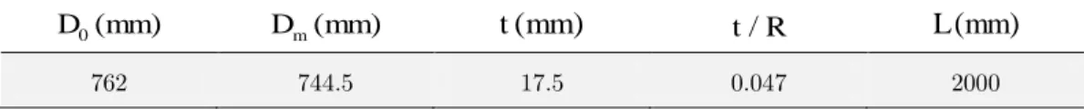
Latin A m erican Journal of Solids and Structures 12 (2015) 355-384 The finite element model of the complete pipe and the denting tool is made by defining the diam-eter of the middle surface and the wall thickness (t) of the pipe. The pipe dimensions are present-ed in Table 2. To simulate the denting tool, a spherical rigid surface was uspresent-ed to create the con-tact with the pipe external surface. The indenters are assumed to have diameters of 40, 80 and 160 mm. Internal pressures with various values of atmospheric pressure (0 MPa), 4, 8 and 16 MPa are applied to the pipe.
0( )
D mm Dm(mm) t mm
(
)
t R/ L mm(
)
762 744.5 17.5 0.047 2000
Table 2: Pipe dimensions.
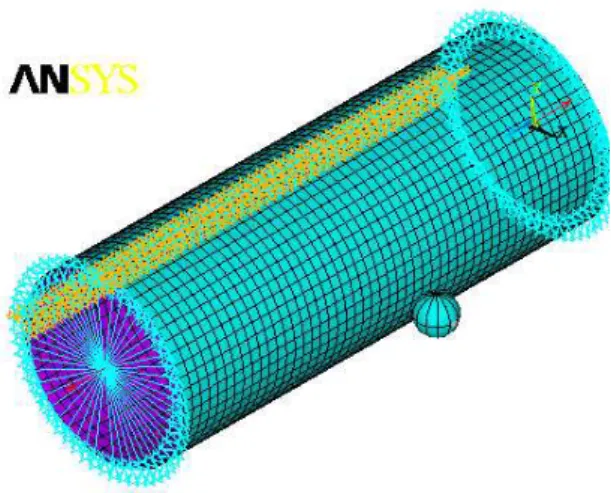
Finite element modeling with ductile damage effect is used to predict the load bearing capacity of the pipe under plain unconstrained dent. The pipe was modeled using 4-noded shell elements, namely SHELL181 with six degrees of freedom at each node (three translations and three rota-tions). The formulation of this element type is well-suited for large strain nonlinear applications. A rigid spherical indenter (TARG170) and contact element (CONTA173) are used to form the dents in the pipe body, where the indenter is displaced by a prescribed distance into the pipe wall and the contact surface element is allocated at the outside surface of the pipe. A surface-to-surface contact condition with a coefficient of friction of 0.3 was allocated between the pipe and the indenter during the denting process. Figure 4 shows the finite element mesh and the analyti-cal surface that simulates the denting tool.
3.2. Denting Method
In this research, the following steps of indentation process and boundary conditions for different values of internal pressure and indenter diameter are performed in FE simulations with and with-out the ductile damage effect. The following boundary conditions are imposed on the pipe:
- The bottom line of the pipe is fixed in order to prevent rigid body movement during denting.
- The cross section at the end of the pipe is fixed only in the vertical direction to allow axial
tensile stress.
The pipe end-cap is not modeled in the simulations in order to reduce the total number of ele-ments in the mesh and to reduce the solution time. For the pressure loading, the inner pipe wall
is assumed to be subjected to pressure P and a tensile stress of magnitude 2 2 2
/( )
i o i
PD D D is applied
to the end face to simulate end-cap conditions.
The indentation process is simulated using the following steps. The pipe is pressurized to the
design pressure (P), boundary conditions are imposed and the indenter is pressed on the pipe.
Latin A m erican Journal of Solids and Structures 12 (2015) 355-384
Figure 4: Finite element mesh, boundary conditions and the analytical surface of the denting tool.
3.3.Validation of the Finite Element Analysis
The finite element analysis is carried out according to the basic procedures reported by Iflefel et al. (2005) and Baek et al. (2012). Baek et al. worked on finite element analysis of API X65 steel pipes under indentation without considering the damage effect. The stress-strain relation of the material is shown in Figure 3.
Mesh convergence study is carried out on API X65 model to have maximum deformation for internal pressure (P=16MPa) and indenter diameter (d=160mm) to obtain adequate refined finite element sizes. Maximum dent depth is considered to be 152mm (Baek et al, 2012). The model of the shell comprises of 32582 nodes and 40321 elements.
3.4.Numerical Implementation of Damage Evolution Equations
Numerical solution of governing equations for ductile fracture models requires time discretization. In the present study, an explicit integration procedure is used to convert the rate form of equa-tions to an incremental form. The numerical integration scheme in FE simulaequa-tions for the (X-W) model is shown below. The value of the ductile damage variable is calculated for each element and deformation loading step. This model obeys a damage rule and by considering the softening effect in the fracture model, the damage variable is included in the plasticity flow for each loading step. Plastic deformation that contributes to damage is calculated by integrating the damage rate measured at the current loading step.
The state of the nonlinear local problem with variables p,
eq n
,D
nand the stress state
nareLatin A m erican Journal of Solids and Structures 12 (2015) 355-384 the time interval. The task is to solve for the stress tensor and the internal variables at time
1 n n
t
t t.Given:
p, , ,
eq n Dn n
and
n1
nat timet
n.Calculate:
p, 1, 1, 1
eq n Dn n
at timetn1 tn t.
Step 1: For FE simulation of ductile fracture model under study, a small value of the displace-ment is imposed on the reference node of the rigid indenter as the first loading step so that the elastic deformation occurs in the pipe, hence no damage is included. Equivalent von Mises stress
of each element for the present loading step is calculated as the trail stress trail1
n
. The value of1 trail n
is substituted into the yield function. If ( 1, ,
, ) 0trail p n Dn M eqn
, the deformation atthis stage of loading is still in the elastic range with no damage, hence:
, 1 ,
1 1 1 0 0 p e trail n n
q n eq n p n n D D
(15)If
0, the deformation is in the elastic-plastic state. For these elements a plastic correctionstep is used to enforce the consistency condition.
Step 2: For each element undergoing the elastic-plastic deformation, the incremental equivalent
plastic strain p
eq
is first calculated. Two internal variables peq
andDare to be updated for the nextloading step.
In (X-W) model, the softening effect and the subsequent weakening factor is considered in the FE simulation. For each loading step the damage variable and accumulated equivalent plastic
strain and stress is updated. The damage at the time
t
n 1 is found based on the damage rule asdefined in Eq. (6):
1 1
, ,
,
p m p
eq
n n
f n f
eq n
n
D D m
(16) where,
2 , 0 2 11 1 / 0 0.5
3
1 2
1
1 1 / 0.5 1
3
1 2 (1 )
n n
n Lim n
n
f n f
n n
n Lim n
n q Ln p p
q Ln p p
Latin A m erican Journal of Solids and Structures 12 (2015) 355-384 The update on the equivalent plastic strain is:
, 1 ,
ε
ε
pε
pe p
eq n
q n
eq (18)The stress update at the time
t
n 1 is calculated based on the updated weakening factor:1 ( 1) (1 1) n w Dn n Dn n
(19)All necessary field variables
n1, eq np, 1,Dn1
are updated at the time,t
n1
t
nt
.Step 3: For the proposed fracture model, the new incremental strain is imposed and step 1 of the algorithm is restarted until the fracture criterion is satisfied for a given element, i.e. the integral
overD, reaches the value of one. At this time, the fracture occurs and the calculation is
terminat-ed. The load and dent depth relating to this situation is considered as the critical value for the pipe under indentation.
4. RESULTS AND DISCUSSION
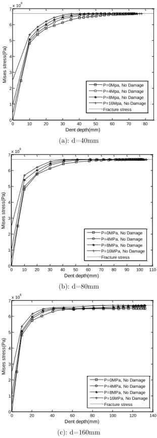
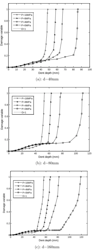
The failure load i.e. the load bearing capacity of the pipe is not directly predicted by ANSYS program since the failure criterion is not included in the material properties. However, it would be possible to find this target load by employing an appropriate failure model. In this paper, we use both plasticity and damage effects to estimate load bearing capacity of the Aluminum pipe under indentation. From finite element analyses of the indented pipes reported in previous works (Iflefel et al, 2005, Baek et al, 2012), one can conclude that pipe subjected to higher value of in-ternal pressure have its maximum strain in the indented zone. In this study, the target dent depth as an indication of load bearing capacity for each combination of indenter diameter and internal pressure is obtained when the value of the non dimensional damage parameter becomes equal to unity.
Latin A m erican Journal of Solids and Structures 12 (2015) 355-384 (a): d=40mm
(b): d=80mm
(c): d=160mm
Figure 5: Variation of maximum von Mises stress with dent depth without damage effect, P is a parameter: (a) D=40mm, (b) D=80mm, (c) D=160mm.
0 10 20 30 40 50 60 70 80 0 1 2 3 4 5 6 7x 10
8 Dent depth(mm) M is e s s tre s s (Pa )
P=0Mpa, No Damage P=4Mpa, No Damage P=8Mpa, No Damage P=16Mpa, No Damage Fracture stress
0 10 20 30 40 50 60 70 80 90 100 110 0 1 2 3 4 5 6 7x 10
8 Dent depth(mm) M is e s s tre s s (Pa )
P=0MPa, No Damage P=4MPa, No Damage P=8MPa, No Damage P=16MPa, No Damage Fracture stress
0 20 40 60 80 100 120 140
0 1 2 3 4 5 6 7x 10
8 Dent depth(mm) M is e s s tre s s (Pa )
Latin A m erican Journal of Solids and Structures 12 (2015) 355-384
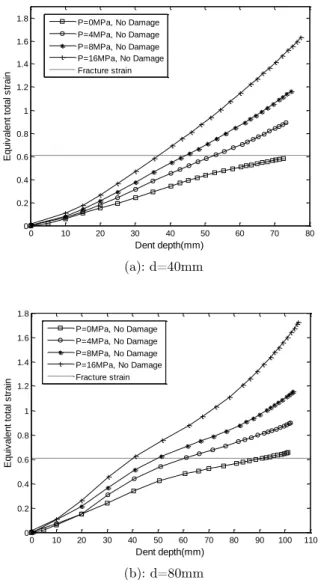
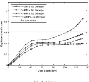
Figure 6 displays variation of the maximum equivalent total strain versus the dent depth for dif-ferent values of indenter diameters under various internal pressure loadings without the damage effect. The true fracture strain of Al 2024-T351 under uniaxial tension test according to Figure 3 is almost equal to 0.6. Since the effect of damage is not considered in Figure 6, the value of frac-ture strain is passed over this strain fracfrac-ture limit. On the other hand the finite element program without damage effect will continue till deformation in the pipe becomes unstable. This defect can be removed by considering ductile damage effect in the simulations and a better approximation for fracture initiation in the material is found. As depicted in Figure 6, the dent depth at the point with fracture strain value of around 0.6, decreases as the internal pressure increases. More-over, as the indenter diameter increases, the dent depth corresponding to the fracture strain in-creases.
(a): d=40mm
(b): d=80mm
0 10 20 30 40 50 60 70 80
0 0.2 0.4 0.6 0.8 1 1.2 1.4 1.6 1.8
Dent depth(mm)
Eq
u
iv
a
le
n
t
to
ta
l
s
tra
in
P=0MPa, No Damage P=4MPa, No Damage P=8MPa, No Damage P=16MPa, No Damage Fracture strain
0 10 20 30 40 50 60 70 80 90 100 110 0
0.2 0.4 0.6 0.8 1 1.2 1.4 1.6 1.8
Dent depth(mm)
Eq
u
iv
a
le
n
t
to
ta
l
s
tra
in
Latin A m erican Journal of Solids and Structures 12 (2015) 355-384 (c): d=160mm
Figure 6: Variation of maximum equivalent total strain with dent depth without damage effect, P is a parameter: (a) D=40mm, (b) D=80mm, (c) D=160mm.
It is observed from Equation (8) that when the damage effect is considered, material strength is
decreased by introducing weakening function (1 D ) to the matrix strength for all indenter
diame-ters and internal pressures. Certainly this reducing effect on the strength of material leads to an increase in the maximum total strain for all similar loading cases. It is shown in Equation (6) that the value of the ductile damage parameter is directly depended on the amount of accumulated plastic strain. The distribution function and final values of equivalent strain and stress at each dent depth depend on the value of the ductile damage parameter. Hence, it may be concluded from Figures 5 and 6 that for each indenter diameter, the pipe under the effect of higher internal pressure loading i.e. 16 MPa, reaches to the critical value of ductile damage parameter at a higher rate and experiences the lowest value of the target dent depth.
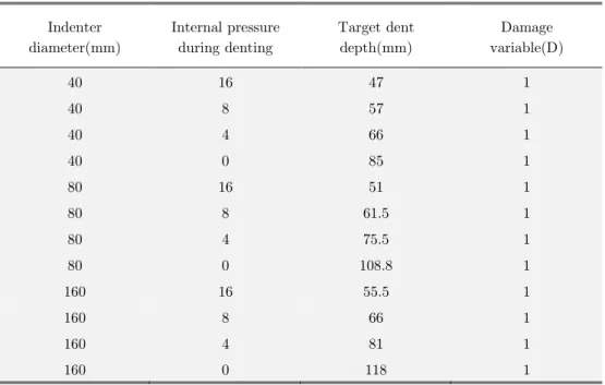
Values of the ductile damage variable for different indenter diameters and internal pressures are obtained by finite element analysis and shown in Table 3. For each indenter diameter, the lowest target dent depth is found to be for the pipe with maximum internal pressure, i.e. 16 MPa. It is also found from Table 3 that as the diameter of the indenter increases, the target dent depth corresponding to the same internal pressure increases. Moreover as the diameter of the indenter decreases, the value of the target dent depth for all internal pressure decreases. The main reason may be due to the stress concentration effect. A high stress concentration is created during the process of generating a dent by an indenter with a smaller diameter. Hence, the accumulated plastic strain and the resulting damage parameters are increased.
0 20 40 60 80 100 120 140
0 0.2 0.4 0.6 0.8 1
Dent depth(mm)
Eq
u
iv
a
le
n
t
to
ta
l
s
tra
in
Latin A m erican Journal of Solids and Structures 12 (2015) 355-384 Indenter
diameter(mm)
Internal pressure during denting
Target dent depth(mm)
Damage variable(D)
40 16 47 1
40 8 57 1
40 4 66 1
40 0 85 1
80 16 51 1
80 8 61.5 1
80 4 75.5 1
80 0 108.8 1
160 16 55.5 1
160 8 66 1
160 4 81 1
160 0 118 1
Table 3: Variation of target dent depth with indenter diameter for different internal pressure loadings.
Latin A m erican Journal of Solids and Structures 12 (2015) 355-384 (a): d=40mm
(b): d=80mm
(c): d=160mm
Figure 7: Ductile damage variable versus dent depth with the internal pressure as a parameter for indenter diameter of: (a) d=40mm, (b) d=80mm, (c) d=160mm.
0 10 20 30 40 50 60 70 80 90 100 0 0.2 0.4 0.6 0.8 1
Dent depth (mm)
D a m a g e v a ri a b le P=16MPa P=8MPa P=4MPa P=0MPa D=1
0 20 40 60 80 100 120
0 0.2 0.4 0.6 0.8 1
Dent depth (mm)
D a m a g e v a ri a b le P=16MPa P=8MPa P=4MPa P=0MPa D=1
0 20 40 60 80 100 120 0 0.2 0.4 0.6 0.8 1
Dent depth (mm)
Latin A m erican Journal of Solids and Structures 12 (2015) 355-384
The relation between the dent depth and denting force for initial internal pressures equal to 8 and 16 MPa and various indenter diameters with and without damage effect are shown in Figure 8. Residual dent depths were obtained from the loading-unloading curves to evaluate the spring back behavior. The force employed to obtain the predetermined dent depth considering the dam-age effect is found to be lower than that obtained without the damdam-age effect. In both simulations, as the indenter diameter and the initial internal pressure increases, the value of applied force creases. The slope of the force versus the dent depth slightly increases as the dent depth and in-ternal pressure increases. When the damage effect is considered, the amount of plastic defor-mation and accordingly the residual dent depth is increased in comparison with the case without damage effect.
(a): P=8MPa
(b): P=16MPa
Figure 8: Comparison of force versus dent depth response with and without damage effect for various indenter diameters and internal pressures of: (a) 8 MPa, and (b) 16 MPa.
0 10 20 30 40 50 60 70
0 2 4 6 8 10 12x 10
5
Dent depth (mm)
F
o
rc
e
(N
)
d=160mm, Damage d=80mm, Damage d=40mm, Damage d=160mm, No Damage d=80mm, No Damage d=40mm, No Damage
0 10 20 30 40 50 60
0 2 4 6 8 10 12
x 105
Dent depth (mm)
F
o
rc
e
(N
)
Latin A m erican Journal of Solids and Structures 12 (2015) 355-384 Table 4 presents the failure force, stress and equivalent plastic strain corresponding to the ele-ment with the highest value of ductile damage parameter at the vicinity of target dent depth. As predicted before, for each combination of internal pressure and indenter diameter, the von Mises stress is found to be lower and the equivalent plastic strain to be higher than the case without the damage effect. At the final stage of loading, the value of stress falls rapidly to zero
for small value of loading increment (i.e., 5mm) and the corresponding ductile damage
pa-rameter reaches to one, i.e. D
1
. Due to this reason we are not able to present its variationexact-ly at the target dent depth and a point very close to the target dent depth is chosen.These values are compared with those corresponding to the same element without the damage effect. It is found that the failure force increases linearly with increasing indenter diameters regardless of the internal pressure.
Indenter diameter (mm)
Initial internal pressure (MPa)
Simulation with damage effect Simulation without damage effect
Max force (KN)
von Mises stress (MPa)
Equivalent plastic
strain
Ductile damage variable (D)
Max force (KN)
von Mises stress (MPa)
Equivalent plastic
strain
40 16 735.8 81.29 0.2985 0.93 798.6 598.5 0.1951
40 8 703.6 101.2 0.3156 0.89 761.7 593.1 0.1859
40 4 659.4 121.4 0.3312 0.87 728.5 589.9 0.1754
40 0 501.13 77.67 0.4002 0.95 675.2 582.9 0.15996
80 16 861.6 189.9 0.3666 0.87 965.9 631.1 0.2835
80 8 809.6 203.31 0.4046 0.84 879.4 641.3 0.3242
80 4 782.8 88.21 0.4696 0.93 883.5 642.1 0.3299
80 0 801.1 191.1 0.3863 0.88 896.8 639.1 0.3137
160 16 1144.2 83.64 0.3275 0.94 1196.4 614.9 0.2365
160 8 1008.7 68.81 0.3657 0.95 1051.6 626.6 0.2696
160 4 1010.2 182.02 0.3605 0.85 1031.1 630.8 0.2827
160 0 1012.2 162.4 0.3735 0.87 1025.8 632.1 0.2875
Table 4: Failure force, stress and equivalent plastic strain for element with maximum ductile damage parameter in vicinity of target dent depth.
Latin A m erican Journal of Solids and Structures 12 (2015) 355-384
element under study has contact with the indenter, however as the dent depth increases, the con-tact between the element and the indenter is reduced and stress relaxation occurs. Hence, as shown in Figures 9.b and c, at some dent depths the von Mises stress is decreased and then at later stages increased until some points close to the target dent depth at which it again decreases and finally falls to zero. For indenter diameters of 80 and 160mm the conditions is more obvious in the pipe without internal pressure, i.e. P=0MPa, than other internal pressure. It is expected that in the dent depths at which the stress relaxation occurs the equivalent plastic strain remains constant. However, for indenter diameter of 40mm, the highly effected element always remains in contact with the indenter and stress relaxation does not occur.
(a): d=40mm
(b): d=80mm
0 10 20 30 40 50 60 70 80 90 0
1 2 3 4 5 6 7x 10
8
Dent depth (mm)
M
is
e
s
s
tre
s
s
(Pa
)
P=16MPa, Damage P=8MPa, Damage P=4MPa, Damage P=0MPa, Damage Fracture stress
0 20 40 60 80 100 120
0 1 2 3 4 5 6 7x 10
8
dent depth (mm)
M
is
e
s
s
tre
s
s
(Pa
)
Latin A m erican Journal of Solids and Structures 12 (2015) 355-384 (c): d=160mm
Figure 9: Comparison of von Mises stress versus dent depth in element with maximum ductile damage parameter, for different internal pressures: (a) D=40mm, (b) D=80mm, (c) D=160mm.
Moreover, Figure 10 displays the equivalent plastic strain versus dent depths for indenters with different diameters under various internal pressure loadings for the element with maximum duc-tile damage parameter. According to Figure 10, the distribution of equivalent plastic strain at each dent depth depends on the corresponding value of the ductile damage parameter. As stated in the previous paragraph regarding Figure 9, it can be concluded that due to the stress relaxa-tion caused by loss of full contact between the spherical indenter with diameters 80 and 160mm and the pipe during the denting process, values of equivalent plastic strains remain constant in Figures 10.b and c. It is also observed that at later stages, the contact between the concerned element and the indenter is again made and the equivalent plastic strain is then increased. For these indenter diameters, at initial stages the pipe with higher value of internal pressure has the lowest value of equivalent plastic strain. However, for indenter diameter of 40mm the equivalent plastic stain always increases rapidly and aforementioned case does not occur.
(a): d=40mm
0 20 40 60 80 100 120 0
1 2 3 4 5 6 7x 10
8
Dent depth (mm)
M
is
e
s
s
tre
s
s
(Pa
)
P=16Mpa, Damage P=8Mpa, Damage P=4Mpa, Damage P=0Mpa, Damage Fracture stress
0 10 20 30 40 50 60 70 80 90 0
0.05 0.1 0.15 0.2 0.25 0.3 0.35 0.4 0.45
Dent depth
Eq
u
iv
a
le
n
t
p
la
s
ti
c
s
tra
in
Latin A m erican Journal of Solids and Structures 12 (2015) 355-384 (b): d=80mm
(c): d=160mm
Figure 10: Comparison of equivalent plastic strain versus dent depth in element with maximum ductile damage parameter, for different internal pressures: (a) D=40mm, (b) D=80mm, (c) D=160mm.
To illustrate the effect of damage on the process of pipe denting, variations of equivalent plastic strain and Mises stress in the axial direction of the pipe for an arbitrary internal pressure i.e. of 16 MPa, indenter diameter of 160mm that has the target dent depth of 57mm with and without the damage effect are shown in Figure 11. It is found that around the middle length of the pipe at which the contact occurs, the effect of damage is more obvious. In these points, the equivalent plastic increases and Mises stress decreases until it falls to zero when the ductile damage parame-ter approaches to one.
0 20 40 60 80 100 120 0
0.05 0.1 0.15 0.2 0.25 0.3 0.35 0.4 0.45 0.5
Dent depth (mm)
Eq
u
iv
a
le
n
t
p
la
s
ti
c
s
tra
in
P=16MPa, Damage P=8MPa, Damage P=4MPa, Damage P=0MPa, Damage
0 20 40 60 80 100 120
0 0.05 0.1 0.15 0.2 0.25 0.3 0.35 0.4
Dent depth (mm)
Eq
u
iv
a
le
n
t
p
la
s
ti
c
s
tra
in
Latin A m erican Journal of Solids and Structures 12 (2015) 355-384
(a) (b)
Figure 11: Variation of the equivalent plastic strain and Mises stress in the axial direction of the pipe, P=16MPa, d=160mm with and without damage effect: (a) equivalent plastic strain (b) Mises stress
The springing back behavior of the dented pipe with variations in the indenter size and initial internal pressure, with and without damage effect is shown in Table 5. The process of introducing a dent into a pipe involves both elastic and plastic deformation. The dent depth is changed from the predetermined depth to a residual dent depth when the indenter is removed. The depth of a dent in a pipe changes as the internal pressure changes. The response of a dent depends on its prior loading history. The spring back ratio is calculated from the following formula:
target dent depth residual dent depthspring back % 100
target dent depth
The spring back behavior of the dented pipe is related to the pipe geometry, material properties and pressure loading condition (Cosham and Hapkins, 2004). Now considering the results of this paper, i.e. Table 5, one can say that the damage effect is influenced by spring back ratio. This is mainly due to the fact that the damage effect contributes to higher values of plastic deformation which is proportional to the damage parameter. Hence, in this case the residual dent depth in-creases and the spring back ratio dein-creases in comparison with the case where the damage effect is not considered. It is also found that the denting introduced to a pressurized pipe shows higher value of springing back in comparison with dents on an unpressurised pipe. The springing back is found to be strongly affected by the internal pressure as shown in Table 5.
0 0.2 0.4 0.6 0.8 1 1.2 1.4 1.6 1.8 2 0
0.05 0.1 0.15 0.2 0.25 0.3 0.35
Axial direction of pipe (m)
Eq
u
iv
a
le
n
t
p
la
s
ti
c
s
tra
in
P=16MPa, d=160mm, Damage P=16MPa, d=160mm, No Damage
0 0.2 0.4 0.6 0.8 1 1.2 1.4 1.6 1.8 2 0
1 2 3 4 5 6 7x 10
8
Axial direction of pipe (m)
M
is
e
s
s
tre
s
s
(Pa
)
Latin A m erican Journal of Solids and Structures 12 (2015) 355-384 Indenter
diame-ter(mm)
Internal pressure during denting
Target dent depth(mm)
with damage effect without damage effect
Spring back (%) Spring back (%)
40 16 47 41.7 45.18
40 8 57 32.52 35.36
40 4 66 28.71 32
40 0 85 19.22 26.63
80 16 51 45 48.48
80 8 61.5 33.18 36.55
80 4 75.5 27.53 31.65
80 0 108.8 20.60 23.44
160 16 55.5 54.62 56.51
160 8 66 38.62 39.56
160 4 81 31.97 33.01
160 0 118 22.17 22.74
Table 5: Spring back effect for different indenter diameters, dent depths and initial internal pressures, with and without damage effect.
5. CONCLUSIONS
The ductile damage behavior of the Aluminum 2024-T351 alloy pipe with a dent defect on the
pipe body is investigated using finite element analysis. In the elastic–plastic finite element
analy-sis the (X-W) damage plasticity model is introduced to obtain variations of the load bearing ca-pacity and failure depth for several indenter sizes and internal pressures. The proposed damage plasticity model includes material deterioration, pressure sensitivity, Lode angle dependence and nonlinear damage evolution law. The numerical implementation of damage evolution equation is simple with a good physical understanding.
equiva-Latin A m erican Journal of Solids and Structures 12 (2015) 355-384 lent plastic strain in highly affected points in the pipe. Moreover, it is found that the damage has a reducing effect on the spring back ratio of the dented zone of the pipe.
It can be concluded that the proposed finite element analysis model with damage effect success-fully handles the elastic-plastic indentation problem of a pipe loaded by rigid spherical indenter and can be extended to a combined loading case of internal pressure and in-plane bending.
References
Alexander, C. R. (1999), Review of experimental and analytical investigations of dented pipelines. Houston. Tex-as: Stress Engineering Services, Inc.
Allouti, M. Schmitt, C. Pluvinage, G. Gilgert, J. Hariri, S. (2012), Study of the influence of dent depth on the critical pressure of pipeline. Engineering Failure Analysis. 21, 40-51.
Allouti. M., Schmitt. C., Pluvinage. G. (2014), Assessment of a gouge and dent defect in a pipeline by a combined criterion, Engineering Failure Analysis, 36, 1–13.
Ansys engineering analysis system: ver. 12. ANSYS, Inc.
Baek, J. Kim, Y. Kim, W. Koo, J. Seok, Ch. (2012), Load bearing capacity of API X65 pipe with dent defect under internal pressure and in-plane bending. Materials Science and Engineering A. 540, 70-82.
Bai, Y. Wierzbicki, T. (2010), Application of extended Mohr–Coulomb criterion to ductile fracture. Int. J. Fract. 161, 1–20.
Blachut, J. Iflefel, I.B. (2007), Collapse of pipes with plain or gouged dents by bending moment. International Journal of Pressure Vessels and Piping. 84, 560–571
Blachut, J. Iflefel, I.B. (2007), Analysis of plain and gouged dents is steel pipes subjected to pressure and moment loading, Proceedings of the PVP2006-ICPVT-11 conference on design and analysis, New Yor’: ASME, 3, 1–9. Blachut, J. Iflefel, I.B. (2008), Experimental and Numerical Investigation of Plain and Gouged Dents in Steel Pipes Subjected to Pressure and Moment Loading, ASME MAY, 130.
Borvik, T. Hopperstad, O. S. Berstad, T. Langseth, M. (2001), A computational model of viscoplasticity and ductile damage for impact and penetration. European journal of mechanics. A. Solids. 20, 685–712.
Bridgman, P. W. (1952), Studies in large plastic flow and fracture. McGraw-Hill Inc.
Brünig, M, Albrecht, D, Gerke, S, 2011, Numerical analysis of stress-triaxiality-dependent inelastic deformation behavior of aluminum alloys. International Journal of Damage Mechanics. 20, 299-317.
Brünig, M. Gerke, S. Hagenbrock, V. 2013, Micro-mechanical studies on the effect of stress triaxiality and the Lode parameter on ductile damage. International Journal of Plasticity. 50, 49-65.
Brünig, M. Gerke, S. Brenner, D. (2014), New 2D-Experiments and Numerical Simulations on Stress-State-Dependence of Ductile Damage and Failure. Procedia Materials Science. 3, 177 – 182.
Cosham, A. Hopkins, P. (2004), The effect of dents in pipelines-guidance in the pipeline defect assessment manu-al. International Journal of Pressure Vessels and Piping. 81, 127–139.
Dunand, D. Mohr, D. (2011), On the predictive capabilities of the shear modified Gurson and the modified Mohr– Coulomb fracture models over a wide range of stress triaxialities and Lode angles. Journal of the Mechanics and Physics of Solids. 59,1374-1393.
Latin A m erican Journal of Solids and Structures 12 (2015) 355-384
Hojjati, M. H. Lukasiewicz, S.A. (2008), Filtering algorithm for radial displacement measurements of a dented pipe, International Journal of Pressure Vessels and Piping, 85, 344–349.
Hyde, T.H. Luo, R. Becker, A.A. (2005), Elastic–plastic response of unpressurised pipes subjected to axially-long radial indentation. International Journal of Mechanical Sciences. 47, 1949–1971.
Hyde, T.H. Luo, R. Becker, A.A. (2005b), Prediction of force–deflection behavior of pressurized pipes subjected to axially long radial indentation. International Journal of Pressure Vessels and Piping. 82, 625–637.
Hyde, T.H. Luo, R. Becker, A.A. (2007), Elastic–plastic analysis of offset indentations on unpressurised pipes. International Journal of Solids and Structures. 44, 399–418.
Hyde, T.H. Luo, R. Becker, A.A. (2009), Analysis of stresses in pipes indented by long external indentations and subsequent stress variations due to pressure fluctuations, International Journal of Pressure Vessels and Piping, 86 ,428–434.
Iflefel, I.B. Moffat, D.G. Mistry, J. (2005), The interaction of pressure and bending on a dented pipe. Internation-al JournInternation-al of Pressure Vessels and Piping. 82, 761–769 .
Johnson, G.R. Cook, W.H. (1985), Fracture characteristics of three metals subjected to various strains, strain rates, temperatures and pressures. Engineering Fracture Mechanics. 21, 31– 48.
Lemaitre, J. (1985), A continuous damage mechanics model for ductile fracture. Journal of Engineering Materials and Technology - Trans. of the ASME. 107, 83–89.
Lemaitre, J. (1992), A Course on Damage Mechanics. Springer, Berlin, New York.
Mohr, D. Oswald, M. (2008), A new experimental technique for the multi-axial testing of advanced high strength steels. Exp. Mech. 48, 65–77.
Mohr, D. Dunand, M. Kim, K.H. (2010), Evaluation of associated and non-associated quadratic plasticity models for advanced high strength steel sheets under multi-axial loading. Int. J. Plast. 26, 939–956.
Nahshon, K. Hutchinson, J. W. (2008), Modification of the Gurson model for shear failure. Euro J Mech A: Sol-id.27, 1–17.
Norris, D. M. Reaugh, J. E. Moran, B. Quinnones, D. F. (1978), A plastic-strain mean-stress criterion for ductile fracture. Journal of Engineering Materials. 100, 279–286.
Park, T. D. Kiryakids, S. (1996), on the collapse of the dented cylinders on the external pressure. International of mechanical science. 38, 557-578.
Rosenfeld, M. J. Porter, P. C. Cox, J. A. (1998), Strain estimation using VETCO deformation tool, Data interna-tional pipeline conference. ASME. 1.
Tvergaard, V. (1981), Influence of voids on shear band instabilities under plane strain conditions. International Journal of Fracture. 17, 389–407.
Wilkins, M.L. Streit, R.D. Reaugh, J.E. (1980), Cumulative-strain-damage model of ductile fracture: Simulation and prediction of engineering fracture tests. Technical Report UCRL- 53058, Lawrence Livermore National Labor-atory.
Xue, L. (2007), Ductile Fracture Modeling - Theory, Experimental Investigation and Numerical Verification, PHD thesis, Massachusetts institute of technology.
Xue, L. (2007), Damage accumulation and fracture initiation in uncracked ductile solids subject to triaxial load-ing, International Journal of Solids and Structures. 44, 5163–5181.
Xue L. (2008), Constitutive modeling of void shearing effect in ductile fracture of porous materials. Engng Fract Mech.75, 3343–66.
Xue, L. (2009), Stress based fracture envelope for damage plastic solids, Engineering Fracture Mechanics. 76, 419–
Latin A m erican Journal of Solids and Structures 12 (2015) 355-384 Xue, L. Belytschko, T. (2010), Fast methods for determining instabilities of elastic–plastic damage models through closed-form expressions, Int. J. Numer. Meth, Engng. 84, 1490–1518.
Xue, L. Huang, H. (2009), Prediction of slant ductile fracture using damage plasticity theory, International Jour-nal of Pressure Vessels and Piping. 86, 319–328.
Xue, L. Wierzbicki, T. (2008), Ductile fracture initiation and propagation modeling using damage plasticity theo-ry, Engineering Fracture Mechanics. 75, 3276–3293.
Xue, L. Wierzbicki, T. (2009), Ductile fracture characterization of aluminum alloy 2024-T351 using damage plas-ticity theory, International Journal of Applied Mechanics. 2, 267–304.
Xue, L. Wierzbicki, T. (2009), Numerical simulation of fracture mode transition in ductile plates, International Journal of Solids and Structures. 46, 1423–1435.
Zeinoddini. M., Arabzadeh. H ., Ezzati . M.,. Parke. G.A.R. (2013),Response of submarine pipelines to impacts from dropped objects: Bed flexibility effects, International Journal of Impact Engineering, 62, 129-141.
Nomenclature
Letters
A Stress asymmetry in Wilkins et al. model
d Indenter diameter
D Ductile damage
cr
D Material constant
o
D Outer diameter of pipe
L length of pipe
m
Damage exponent in Xue-Wierzbicki modeln
Strain hardening exponentp Hydrostatic pressure
P Internal pressure of pipe
cut off
p Cut-off pressure above which fracture occurs in hydrostatic tension in Xue-Wierzbicki model
lim
p Limiting pressure below which no damage occurs in Xue-Wierzbicki model
q
Exponent in pressure dependence function in Xue-Wierzbicki model1,2,3
S Maximum, intermediate and minimum principal deviatoric stress components
t
Wall thickness of pipeGreek letters
Exponent in weakening function in Xue-Wierzbicki model
Ratio of fracture strains at
0.5
and at 0 in Xue-Wierzbicki model ( )p p
Pressure dependence function in Xue-Wierzbicki model
( )
Lode angle dependence function in Xue-Wierzbicki model
c
Critical strain to failure (up limit of integral)p eq
Equivalent plastic strainf
Latin A m erican Journal of Solids and Structures 12 (2015) 355-384
0 f
Reference equivalent fracture strain in Xue-Wierzbicki model
eq
Von Mises equivalent stress
m
Mean stressM
Matrix strength1,2,3
Maximum, intermediate and minimum principal stress components