20 artigo 421
CASE REPORT
1 – Head of Clinic; Director of the Integrated Surgical Management Area 2 of HUC; In charge of the Knee Surgery Unit of HUC; Assistant Professor of the School of Medicine of Coimbra, Portugal.
2 – Orthopedic Resident at HUC – Coimbra, Portugal.
3 – Assistant Professor of Universidade de Aveiro, Department of Mechanical Engineering Biomechanics Investigation Group – Coimbra, Portugal. Study conducted at the Orthopedic Clinic of HUC – Coimbra, Portugal
Mailing Address: Rua Larga – 3004-504 – Coimbra, Portugal. Email: [email protected] Study received for publication: 9/22/2010, accepted for publication: 5/25/2011.
TIBIAL PERIPROSTHETIC FRACTURE COMBINED WITH TIBIAL STEM
STRESS FRACTURE FROM TOTAL KNEE ARTHROPLASTY
Fernando Fonseca1, Edgar Rebelo2, António Completo3
7KHDXWKRUVGHFODUHWKDWWKHUHZDVQRFRQIOLFWRILQWHUHVWLQFRQGXFWLQJWKLVZRUN
This article is available online in Portuguese and English at the websites: www.rbo.org.br and www.scielo.br/rbort
ABSTRACT
Total knee arthroplasty complications related to the prosthetic material are very rare, except for polyethylene wear. We report the case of a 58-year-old woman who came to the emergency service of our hospital with a periprosthetic tibial fracture (Mayo Clinic type I). Careful examination showed that this fracture was concomitantly associated with a tibial stem fatigue fracture. The pros-thesis and the stem were sent to an independent biome-chanics laboratory for evaluation. A finite-element CAD system was used to make a reconstruction, so as to
as-certain whether there had been any manufacturing defect and what the causes of the event might have been. After evaluation of several hypotheses, it was concluded that the fracture in the prosthetic material had been caused by overloading at the plate/stem transition zone secondary to previous bone failure (fracture). From the evaluation of this case, the need to make appropriate assessment of bone mineralization can again be emphasized. In cases of doubt, a longer stem should be used.
Keywords – Arthroplasty, Replacement, Knee; Fractures, Stress; Reoperation
INTRODUCTION
In 1984, Mendes et al described a baseplate fracture of the tibial component of total knee arthroplasty(1), a case that is not unique in literature(2-4), although in monoblock tibial components (base and single stem). However, due to market requirements, many compa-nies sell modular tibial components with the base and tibial stem separate, with assembly executed upon de-ployment. These solutions produce an increase in the concentration of loads(5) in the transition zone, which, according to manufacturers, is below the resistance limit of the material. Among periprosthetic bone frac-tures of the knee, the tibial fracture is equally rare(6). This case reports a phenomenon of association of two different fractures (bone and metal) simultaneously in the same patient, a fact that to the best of our know-ledge does not appear reported in literature.
CLINICAL FACT
746
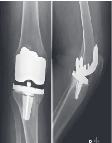
Figure 1 – ;UD\XSRQDGPLVVLRQ
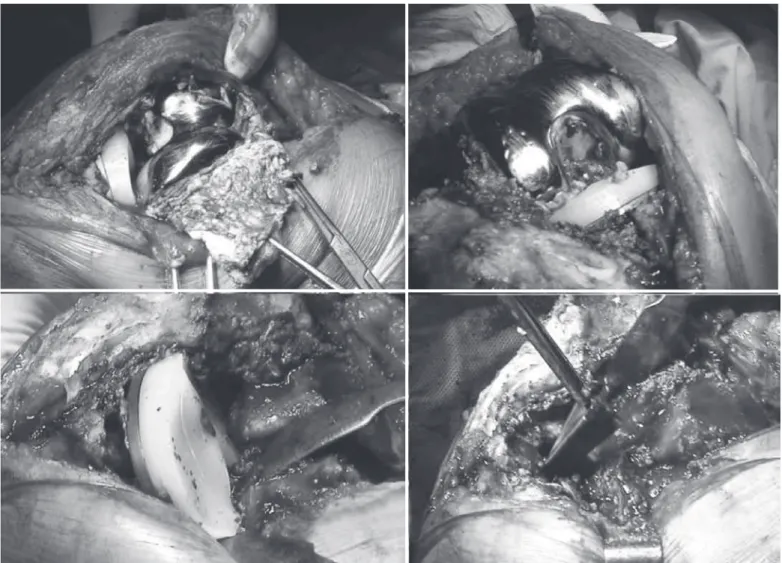
A knee radiograph was taken at the same time (Figure 1) and the patient was admitted to our clinic with a diagnosis of Mayo Clinic type IB tibial peri-prosthetic fracture(3). During surgical preparation and planning there was a more careful observation of the images, with detection of a tibial stem fracture at the tibial stem/baseplate transition (Figure 1). In view of these new data, the decision was made to conduct a review with deployment of total knee arthroplasty. In the perioperative period and after extraction of the tibial component the stem fracture was con-firmed unequivocally (Figure 2). Both components and stems were replaced, and a tibial wedge (P.F.C. Sigma TC3 – Depuy Orthopaedics – Warsaw-IN) was included (Figure 3). The postoperative period elapsed without incidents.
Analysis by the finite element method
Various questions were brought up after the patient was treated:
- Was the stem fracture secondary to the bone fracture? - Can the stem fracture have caused instability res-ponsible for the bone fracture?
The extracted total knee replacement implant was sent to a biomechanics laboratory in an attempt to answer these questions. Two finite element models were then developed in order to quantify the tension forces in the stem in a model of the normal knee wi-thout deformity and in a model with varus deformity resembling that found in the patient, with the end of the stem in contact with the lateral tibial cortex, as observed in the radiograph (Figure 1). These models were planned taking into account the patient’s weight (80 kg), the tibial geometry and the geometry of the implants before the fracture as well.
The stress level observed in each one of the models was compared with the fatigue limit of the material that forms the stem and is supplied by the manufac-turer. To build the finite element model according to the patient’s specificity, she underwent frontal and lateral radiographs and a computed tomography, with the presumptive model of the tibia before (Fi-gure 4) and after the varus deformity having been built in a CAD model (Catia, Dassault Systèmes, France). Two volumes are distinguished in the bone model, representing a cortical bone and the other spongy bone of the tibia.
The limit of the transition between the cortical and
spongy bones was calculated in the computed tomog-raphy. This was followed by a scan of the tibial base-plate of their stem in a 3D laser scanner (Roland LPX 250) with a precision of 0.2 mm (Figure 4). The finite elements relating to the arthroplasty were also built in a CAD model (Catia, Dassault Systèmes, France). As the arthroplasty was cemented, a cement man-tle model was created. The set of 3D models created (bone, tibial component, cement) was converted au-tomatically into a model of finite elements using CA-TIA software (Catia, Dassault Systèmes, France). The finite element mesh was built with 4-node elements. The properties of the cortical and spongy bone were calculated by means of tomography(7). The properties of the arthroplasty and bone cement materials consi-dered were provided by the manufacturers (Table 1), assuming that they are homogeneous, isotropic and with linear elasticity.
747
Figure 2 – 7RWDONQHHUHSODFHPHQWZLWKWLELDOVWHPIUDFWXUH
Figure 3 –7RWDONQHHUHSODFHPHQWLPSODQWHG
748
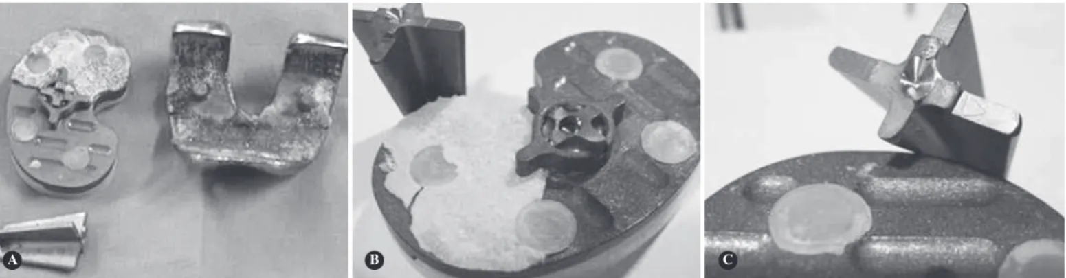
Figure 4 – $7RWDONQHHUHSODFHPHQWZLWKWLELDOVWHPIUDFWXUHq%3HULRSHUDWLYHq&$WWKHODERUDWRU\.
A B C
CATIA V5 (Providence, USA). The cement-implant, implant-bone and implant-polyethylene insert inter-face zones were considered with a specific algorithm. Two load simulations were executed to evaluate forces at the stem level. The first case was a load corresponding to 45% of the gait cycle on the load side just before impulsion by the hallux, with an axial force corresponding to three times the patient’s body weight (3 x 80 kg)(6), distributed over the tibial plate asymmetrically (60% medial and 40% lateral), also considering in this configuration the forces exerted by the patellar tendon (Table 2) according to the patient’s weight (80 kg).
The second case was identical to the first, but with application of axial load only on the medial plate (simulation of severe case of varus deformity).
The von Mises stress forces (Figure 6) were evalu-ated in both cases.
The applied stress forces can be observed in Figure 7, in both situations tested (before and after varus de-formity observed upon admission to the emergency department). The maximum value of the von Mises stress forces before the varus deformity was 27.2MPa, having risen to 54.3MPa in the simulation of varus deformity. In both cases, the maximum value was
found in the medial transition zone between the tibial baseplate and the stem.
The location found in the finite element model in the tibial stem corresponds to the fatigue fracture zone found in the arthroplasty stem implanted in the patient in question. However, in any of the simulations, the values reached were below the stress force limit of the titanium alloy used in the arthroplasty (160MPa in 10 million cycles).
However, it should be stressed that simple varus alignment did not alter the maximum tension zones, but doubled them instead. In addition, we should keep it in mind that the simulation did not consider, due to technical impossibility, loads in more extreme values with the varus deformity, namely in agricultural labor.
DISCUSSION
Tibial component stress fractures from total knee ar-throplasty are very rare, as demonstrated by Chatterji et al(8), who described several possible causes. The same
can be said of tibial periprosthetic bone fractures(9). Scott et al(4) postulated that the varus implantation of the tibial component of a total knee arthroplasty increases the concentration of loads with their asym-metric distribution, and can cause a metal fatigue
frac-Table 1 – &KDUDFWHULVWLFVRIPDWHULDOV
Material
Modulus of elasticity
(GPa)
Poisson’s coefficient
7LELDO EDVHSODWHDQG
VWHP 7LWDQLXP
110
3RO\HWK\OHQH
LQVHUW 3RO\HWK\OHQH
&HPHQW 300$
Table 2 – 7LPHVFRQVLGHUHG
Force/time Designation Value
$[LDO PHGLDOODWHUDO0)/) 1
,QWHUQDOH[WHUQDO
WLPH IE 1P
749
Figure 5 – k1RUPDOyPRGHOEXLOWLQILQLWHHOHPHQWV
Figure 6 – )LQLWHHOHPHQWPRGHORISURVWKHVLVVKRZLQJDKLJK FRQFHQWUDWLRQRIIRUFHVLQWKHWUDQVLWLRQ]RQHRIWKHWLELDOEDVHSODWH VWHPPRGXODUV\VWHP
Figure 7 – 'HWDLOLQWKHVWUHVVIRUFHVDSSOLHGLQWKHkQRUPDOPRGHO ORDGFDVHyDQGLQWKHkYDUXVPRGHOORDGFDVHy
STRESS FRACTURE FROM TOTAL KNEE ARTHROPLASTY
ture. Also the implantation of the tibial component in external rotation was identified as responsible for excessive loads in tibial components, specifically in total condylar III knee(10) arthroplasties, as well as in the polyethylene fitting zone(5,11,12).
The work of Maquet(13) demonstrated that, in the static position, varus knee deformity produces the exponential growth of loads transmitted to the medial tibial plate, not only through the increase of the lever arm but also through the decrease of the load-bearing surface. However, Johnson et al(14) and Harrington(15) report that this increase is mainly in the orthostatic position, since during gait, there is a passage of the load-bearing surface to the medial zone, and, as such,
the load increase is not as intense. The simulations with finite element models showed that a varus de-formity increases stress values in the medial tibial plate 1.7 times below the fatigue resistance value of the bone structure involved, and can justify the strong association between tibial periprosthetic fracture and poor axial alignment(16).
pros-750
thesis, a situation exacerbated in cases of modular tibial components such as in applied arthroplasty. In this case, we went on to study the patient’s local con-ditions, paying attention to bone mass, weight and height of the patient as well as the type of arthroplasty implanted through the finite element method. Analy-sis by the finite element method is an engineering tool whose use is becoming increasingly frequent in the calculation and design of implants and that can become important in cases such as the one described here, as it allows us to simulate the local conditions of implantation of an arthroplasty, contributing to the un-derstanding of possible causes of failure or mistakes committed. The tests showed that the zones of greatest stress are concordant with the alterations observed in the prosthesis removed from the patient, although the maximum load peak was lower than the fatigue limits of the material indicated by the manufacturer, both in the correct position and in the position presented in the patient’s initial assessment. However, it should be noted that the maximum peak of stress doubled from one position to the other, which leaves open the possibility that the patient may have reached the fa-tigue limits, since she was an agricultural laborer and this work entails intense efforts, and above all, very heavy loads and objects for transportation (sometimes between 50 and 100 kg). In the radiograph obtained
upon admission to our hospital, it is not possible to identify poor initial alignment, and we were unable to obtain the immediate postoperative radiograph, but we believe that the varus positioning of the tibial component is secondary to the fracture that will have occurred first and was not identified. Since the patient continued to work and only noticed progressive varus deformity, the bone collapse may have permitted the varus positioning found on the date of admission to our unit, and, taking into account the patient’s type of work, the repeated loads changed significantly, having possibly arrived at or even surpassed the fatigue limit of the titanium alloy, secondarily provoking a fatigue fracture of the material.
Although the cause of a potential fracture risk can-not be attributed to the design of the arthroplasty, this case alerted our attention to this possibility in extreme situations such as the one described here, and was the basis of our decision not to use monoblock tibial plate having abandoned the modular option.
CONCLUSION
This type of case shows the need for clinical and radiographic control of patients for early detection of alterations such as that described.
REFERENCES
1. Mendes DG, Brandon D, Galor L, Roffman M. Breakage of the metal tray in total knee replacement. Orthopedics. 1984;7: 860-2.
2. Abernethy PJ, Robinson CM, Fowler RM. Fracture of the metal tibial tray after Kinematic total knee replacement. A common cause of early aseptic failure. J Bone Joint Surg Br. 1996;78(2):220-5.
3. Hanssen AD, Stuart MJ, Felix NA. Classification of periprosthetic tibial fractures. In: Scuderi GR, Tria AJ, editors. Surgical techniques in total knee arthroplasty. New York: Springer-Verlag; 2002. p. 576.
4. Scott RD, Ewald FC, Walker PS. Fracture of the metallic tibial tray following total knee replacement. Report of two cases. J Bone Joint Surg Am. 1984;66(5):780-2.
5. Flivik G, Ljung P, Rydholm U. Fracture of the tibial tray of the PCA knee. A case report of early failure caused by improper design. Acta Orthop Scand. 1990;61(1):26-8.
6. Taylor SJ, Walker PS, Perry JS, Cannon SR, Woledge R. The forces in the distal femur and the knee during walking and other activities measured by telemetry. J Arthroplasty. 1998;13(4):428-37.
7. Les CM, Keyak JH, Stover SM, Taylor KT, Kaneps AJ. Estimation of material properties in the equine metacarpus with use of quantitative computed tomog-raphy. J Orthop Res. 1994;12(6):822-33.
8. Chatterji U, Ashworth MJ, Smith AL, Brewster N, Lewis PL. Retrieval study of tibial
baseplate fracture after total knee arthroplasty. J Arthroplasty. 2005;20(1):101-7.
9. Rand JA, Coventry MB. Stress fractures after total knee arthroplasty. J Bone Joint Surg Am. 1980;62(2):226-33.
10. McPherson EJ, Vince KG. Breakage of a Total Condylar III knee prosthesis. A case report. J Arthroplasty. 1993;8(5):561-3.
11. Maruyama M, Terayama K, Sunohara H, Adachi T, Suzuki S, Fukuzawa T. Fracture of the tibial tray following PCA knee replacement. A report of two cases. Arch Orthop Trauma Surg. 1994;113(6):330-3.
12. Skinner HB, Mabey MF, Paganelli JV, Meagher JM. Failure analysis of PCA revision total knee replacement tibial component. A preliminary study using the finite element method. Orthopedics. 1987;10(4):581-4.
13. Maquet PGJ. Biomechanics of the Knee: With Applications to the Pathogenesis and the Surgical Treatment of Osteoarthritis. Berlin:Springer-Verlag; 1984.
14. Johnson F, Leitl S, Waugh W. The distribution of load across the knee. A compari-son of static and dynamic measurements. J Bone Joint Surg Br. 1980;62(3):346-9.
15. Harrington IJ. Static and dynamic loading patterns in knee joints with deformi-ties. J Bone Joint Surg Am. 1983;65(2):247-59.