ISSN 1546-9239
© 2008 Science Publications
Corresponding Author: Bojan Zlender, University of Maribor, Faculty of Civil Engineering, Smetanova 17, Postal Code: SI-2000, Maribor, Slovenia, Tel: + 386 2 22 94 300, Fax: + 386 2 25 24 179
Prediction of Permanent Deformation of Pavement’s Unbounded Layers Based on Cyclic
Triaxial Tests
B. Žlender
University of Maribor, Faculty of Civil Engineering,
Smetanova 17, 2000 Maribor, SI Slovenia
Abstract: This research presents an analytical model for determining permanent deformation of pavement's sub-grade and unbound granular base and sub-base material due to cyclic traffic loading. The model is given for interpreting results of repeated load triaxial tests. It considers long term elastoplastic behavior and resilient behavior of sub-grade and unbound granular material. Permanent deformations are expressed as a function of the number of loading cycles and the spherical component and the deviatoric component of the repeated loading. The permanent axial deformation is given as a function of the resilient modulus and the secant modulus for different states of spherical and distortional stresses, and number of loading cycles. By analytical derivation it is presented that the normalized permanent axial strain can be expressed with the modulus values and the parameter D. The moduli are expressed as the functions of the spherical stress component and the distortional stress component. The magnitude of normalized permanent axial strain depends on the limit value of the resilient modulus and ratios between resilient and secant modulus. The parameter D gives the shape of the change of the normalized permanent axial strain with the number of cycles, and is a function of the change of modules with the number of cycles. The applicability of the presented model is demonstrated on the practical example of a repeated load triaxial test of sub-base granular material. Keywords: pavement, sub-grade, unbound base/sub-base granular material, repeated load
triaxial test, resilient modulus, secant modulus, permanent axial strain INTRODUCTION
Pavements are layered structures which are characteristically exposed to low permanent stresses due to self weight and relatively high repeating local loads due to traffic. Traffic influences are demonstrated as dynamic loading at each passage of the repeating load due to a high number of vehicle passages. As a result of each individual dynamical loading compressive and extensional deformation of road layers appear. These deformations are partly elastic and partly inelastic. Inelastic deformations of the individual layers of structures gradually increase due to repeating loading. Through time this is indicated as settlements and unevenness of surface course layer of the pavement. A triaxial apparatus was proved to be appropriate for the determination of elastic and inelastic deformations due to traffic loading.
Analytical models were developed for the description of plastic deformation of unbound granular material. Barksdale[1] found that the permanent axial
strain deformation was proportional to the number of
load cycles at different stress states. After 1972 different authors proposed models for describing the development of permanent axial deformations at different stress states and proportionally with the number of loading cycles N. However, most models were not used in practical calculations in analyses and design of road structures. The weakness of such models is their inapplicability in calculations using FEM. Hornych model[2] was proved to be applicable and it
was used as a comparative one in our research.
In the Laboratory of Soil Mechanics and Foundation Engineering (LMT) the research was performed[3] to investigate the behavior of the unbound
granular material under repeating traffic loading and to determine factors which influence its deformability.
of sub-grade and unbound granular base and sub-base material.
MATERIALS AND METHODS
Repeated load triaxial test: The paper considers repeated load triaxial tests of unbound mixtures performed according to variation cell pressure method and to constant cell pressure method. Some of the results obtained in the laboratories of the company ZAG Ljubljana[4] and LMT[5] were analyzed.
To execute repeated load triaxial tests the proper test equipment is required that comprises: a triaxial cell, a press with appurtenant equipment, measurement equipment, a control system and a data storage system, and computer hardware and software.
The calculation of strength characteristics regarding measured deformation and stress parameters is performed after each individual investigation phase. Measured are the following quantities: cell pressure σ3, vertical stress σ1, vertical strain ε1 and radial strain ε3.
RESULTS AND DISCUSSION
The vertical settlement of pavement is being treated as a consequence of pavement materials and sub-grade materials deformations. The resilient strains r and the
permanent strains p are determined for pavement layers
and sub-grade material at different stress conditions. Resilient modulus: The resilient strain r is taken as the unloading strain from the maximum dynamic stress down to the static contact stress.
The k–θ model[6] could be used to describe the resilient behavior of unbound granular material in repeated load triaxial tests. In this model, the Poisson’s ratio ν is constant. With the k–θ model and a given stress path, we are able to solve the elastic problem. The inelastic problem is solved using a constant Poisson ratio ν and the Young’s modulus E. The expression of volume strains v
r and shear strains q
r and
modulus E, K, G is done using Boyce[7].
The resilient modulus depends on mean and deviatoric stress. Considering both, Uzan et al.[8]
expressed a new model. The modified AASHTO equation has been included for modeling this behavior.
3 2
1 2 3
1 1
K
a oct K
a a
r K
M = ⋅ ⋅ + ⋅ ⋅ +
σ τ σ
σ σ
σ (1)
where a is reference stress (101 kPa), 1, 3, are
principal stresses, oct is octahedral shear stress and K1,
K2, K3 are model parameters.
Permanent deformation: The determination of
permanent deformations of unbound granular material is based on repeated load triaxial tests from standards [9-10] that differ in some details.
The magnitude and development of permanent deformations depend on static stress state of the material, magnitude of cyclic load, magnitude of spherical and deviatoric cyclic load component and the relationship between them, the number of loading cycles, and physical properties of material (density, water content).
The limit state plastic strains are calculated in agreement with the Hornych model[2]. The normalized
axial permanent strain is described with:
− ⋅ = ⋅ =
−B
p A F N A N
100 1 ) ( *
1
ε (2)
where the parameters A and B define deformation growth with number of loading cycles N. The parameter A denotes the limit of the function of permanent axial deformations, the parameter B denotes its deflection. Suggested model for determining permanent deformation: It is derived from measurements of repeated load triaxial test. The material responds to the repeating traffic load with the axial vertical strain ε1 and the radial strain ε2. The stress in material during individual loading varies between the chosen maximum value qmax and the chosen minimum value qmin. The
strain at each individual loading reaches the certain maximum value in compression ε1com and the certain minimum value at unloading ε1ext. The difference
between them is the resilient strain ε1r.
The reproduction of cyclic loading increases the strains ε1com(N) and ε
1ext(N), while the difference
between them ε1r(N) decreases, when material hardens,
and increases, when material softens.
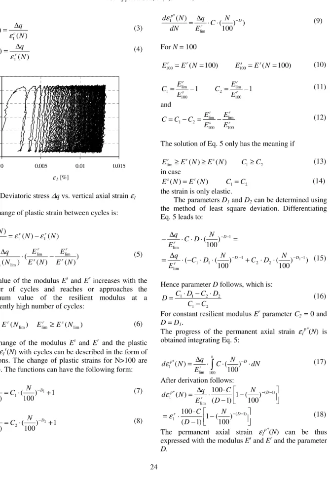
Figure 1 shows the relationship between the distortional stress component q and the axial vertical strain ε1. The relationship between the reloading stress ∆q andthestrain ε1s(N)=∆ε
1com(N) is described with the
secant modulus Es, while the relationship between the unloading stress ∆q and the unloading resilient strain ε1r(N)=∆ε
) ( ) ( 1 N q N
Es c
ε ∆ = (3) ) ( ) ( 1 N q N E r r ε ∆ = (4) 0 10 20 30 40 50 60
0 0.005 0.01 0.015
ε1 [%]
q
[k
Pa
]
Fig 1: Deviatoric stress ∆q vs. vertical axial strain ε1 The change of plastic strain between cycles is:
) ( ) ( ) ( 1 1
1 N N
dN N
d p c r
ε ε ε − = ) ) ( ) ( ( ) ( lim lim lim
lim E N
E N E E N E q r r s r
r ⋅ −
∆
= (5)
The value of the modulus Es and Er increases with the number of cycles and reaches or approaches the maximum value of the resilient modulus at a sufficiently high number of cycles:
) ( )
( lim lim lim
lim E N E E N
Er ≥ r r ≥ s (6)
The change of the modulus Es and Er and the plastic strain ε1r(N) with cycles can be described in the form of
functions. The change of plastic strains for N>100 are ε1r*(N). The functions can have the following form:
1 ) 100 ( ) ( 1 1
lim = ⋅ −D +
s r N C N E E (7) 1 ) 100 ( ) ( 2 2
lim = ⋅ −D +
r r N C N E E (8) and ) ) 100 ( ) ( lim * 1 D r p N C E q dN N d − ⋅ ⋅ ∆ = ε (9)
For N = 100 ) 100 (
100=E N =
Er r ( 100)
100=E N=
Es s (10)
1 100 lim
1= s −
r E E C 1 100 lim
2 = r −
r E E C (11) and r r s r E E E E C C C 100 lim 100 lim 2
1− = −
= (12)
The solution of Eq. 5 only has the meaning if
) ( ) (
lim E N E N
Er ≥ r ≥ s
2
1 C
C ≥ (13)
in case ) ( ) (N E N
Es = r C1=C2 (14)
the strain is only elastic.
The parameters D1 and D2 can be determined using
the method of least square deviation. Differentiating Eq. 5 leads to:
= ⋅
⋅ ⋅ ∆
− − −1
lim ) 100 ( D r N D C E q ) ) 100 ( ) 100 ( ( 1 2 2 1 1 1 lim 2
1− − −
− ⋅ ⋅ + ⋅ ⋅ − ⋅ ∆
= D D
r N D C N D C E
q (15)
Hence parameter D follows, which is:
2 1 2 2 1 1 C C D C D C D − ⋅ − ⋅ = (16)
For constant resilient modulus Er parameter C2 = 0 and
D = D1.
The progress of the permanent axial strain ε1p*(N) is
obtained integrating Eq. 5:
⋅ ⋅ ⋅ ∆ = − n D r
p C N dN
E q N d 100 lim *
1 ( ) (100)
ε (17)
After derivation follows:
− −
⋅ ⋅ ∆
= −( −1)
lim *
1 ( 1) 1 (100)
100 ) ( D r p N D C E q N dε − − ⋅ ⋅
= −( −1)
1 ( 1) 1 (100)
100 D
r N
D C
ε (18)
Table 1: Physical properties of stone materials Type of stone
material of uniformity Coefficient Cu
[-]
Coefficient of curvature Cc[-]
Density
d[g/cm
3]
Optimal water content
wopt [%]
Uncrushed mixture 43 3.5 2.20 5.1
The progress of the permanent axial strain for an arbitrary state of distortional and spherical stress component, can be given, if values of the modulus Es(p,q) and Er(p,q) and the parameter D(p,q) are expressed as the functions of p and q. The stated parameters are expressed using Eq. 1, in such a manner that we get the set of equations from the set of tests, and the values of model parameters K1, K2, K3 are expressed
using the method of least square deviation.
The strain ε1p*(N) can be expressed regarding
spherical and distortional stress components p, q: ) ( ) ( ) , , ( ) , ,
( 1* 0 0
*
1 N p q N p q f p f q
p
p =ε ⋅ ⋅
ε
) ( ) (
0⋅f p ⋅f q
=ε (19)
where the characteristic value of the permanent axial strain ε0 (N) is given at chosen values of the spherical stress component p0 and the distortional stress
component q0. For a chosen value of the permanent
axial strain ε1p*(N), the values of p and q can be expressed from Eq. 19 and the so called deformation lines at a certain number of loading cycles N are obtained. The limit values that lead to failure give the so called failure line of the material.
Example: The applicability of the presented model was verified on the practical example of repeated load triaxial test of sub-grade and base course granular material. The Drava river sub-grade sand and gravel was investigated using repeated load triaxial tests[3, 11].
The results showed the influence of preloading, compaction grade of the material and its moisture content to the deformability. The analysis of development of permanent axial deformations of gravel in the Mura region due to repeated loading was performed[4, 12]. Types of stone material were
determined with regard to the quantity of crushed grains in gravel and to water content. The electro-filter granular material was also investigated[5]. Samples with
and without reinforcements were tested.
Drava river gravel: The investigation of natural gravel quality from the existent deposits in the Drava river region was done in laboratories and in field. Repeated load triaxial tests were performed. Samples of stone material were tested in cycles at different water content. The set of tests on samples with the water content w = wopt ±0.5% re considered. Physical properties of the
analyzed type of stone material are given in Table 1. The determination resilient modulus Er100 and the
secant modulus Es can be obtained from the series of
tests Table 4 with a small number of cycles (N=100). However, parameters Erlim and D are unknown.
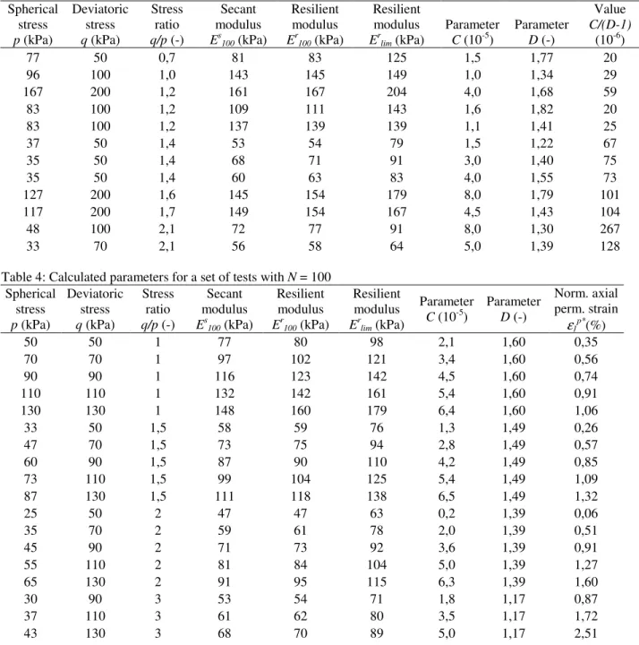
Parameters Erlim and D can be obtained only from
the tests with higher number of cycles. Table 3 presents input data and the modulus Er100, Ec100, Erlim for tests
with the number of cycles N > 20000.
From the measurements modules Er100 and E r
lim, the
secant modulus Es100 and the parameter D are given.
From the results of parameters for a set of tests, modules Er100(p,q), Es100(p,q), Erlim(p,q) and the
parameter D (p, q) are determined using Eq. 1 and the method of least square deviation. Table 2 presents values of the model parameters K1, K2, K3.
Table 2: The calculated model parameters K1, K2, K3
K1 K2 K3
Erlim 757 0,632 -0,012
Er100 599 0,754 -0,010
Es100 590 0,710 -0,010
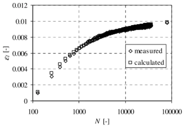
For each test the value of normalized permanent axial strain ε1p*(N) is calculated, and the comparison is
given with a measured value Fig. 2.
Table 3 presents measured and calculated parameters for tests with the number of cycles N > 20000. Table 4 presents calculated parameters and the
0 0.002 0.004 0.006 0.008 0.01 0.012
100 1000 10000 100000
N [-]
ε
1
[-]
measured calculated
Fig. 2: Measured and calculated normalized permanent axial deformation ε1p* vs. the
Table 3: Parameters for a set of tests with N > 20000 Spherical
stress p (kPa)
Deviatoric stress q (kPa)
Stress ratio q/p (-)
Secant modulus Es100 (kPa)
Resilient modulus Er100 (kPa)
Resilient modulus Erlim (kPa)
Parameter C (10-5)
Parameter D (-)
Value C/(D-1) (10-6)
77 50 0,7 81 83 125 1,5 1,77 20
96 100 1,0 143 145 149 1,0 1,34 29
167 200 1,2 161 167 204 4,0 1,68 59
83 100 1,2 109 111 143 1,6 1,82 20
83 100 1,2 137 139 139 1,1 1,41 25
37 50 1,4 53 54 79 1,5 1,22 67
35 50 1,4 68 71 91 3,0 1,40 75
35 50 1,4 60 63 83 4,0 1,55 73
127 200 1,6 145 154 179 8,0 1,79 101
117 200 1,7 149 154 167 4,5 1,43 104
48 100 2,1 72 77 91 8,0 1,30 267
33 70 2,1 56 58 64 5,0 1,39 128
Table 4: Calculated parameters for a set of tests with N = 100 Spherical
stress p (kPa)
Deviatoric stress q (kPa)
Stress ratio q/p (-)
Secant modulus Es100 (kPa)
Resilient modulus Er100 (kPa)
Resilient modulus Erlim (kPa)
Parameter C (10-5)
Parameter D (-)
Norm. axial perm. strain
ε1p*(%)
50 50 1 77 80 98 2,1 1,60 0,35
70 70 1 97 102 121 3,4 1,60 0,56
90 90 1 116 123 142 4,5 1,60 0,74
110 110 1 132 142 161 5,4 1,60 0,91
130 130 1 148 160 179 6,4 1,60 1,06
33 50 1,5 58 59 76 1,3 1,49 0,26
47 70 1,5 73 75 94 2,8 1,49 0,57
60 90 1,5 87 90 110 4,2 1,49 0,85
73 110 1,5 99 104 125 5,4 1,49 1,09
87 130 1,5 111 118 138 6,5 1,49 1,32
25 50 2 47 47 63 0,2 1,39 0,06
35 70 2 59 61 78 2,0 1,39 0,51
45 90 2 71 73 92 3,6 1,39 0,91
55 110 2 81 84 104 5,0 1,39 1,27
65 130 2 91 95 115 6,3 1,39 1,60
30 90 3 53 54 71 1,8 1,17 0,87
37 110 3 61 62 80 3,5 1,17 1,72
43 130 3 68 70 89 5,0 1,17 2,51
normalized axial permanent strain ε1p* for a set of tests
with the number of cycles N = 100.
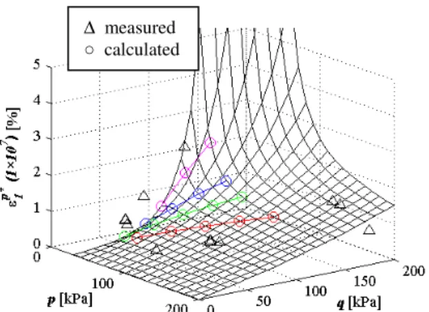
A course of the normalized axial permanent deformation ε1p* could be expressed as a function of the deviatoric stress q and the spherical stress p for each number of cycles, see Fig. 3. The relation between the normalized axial permanent deformation ε1p* and the deviatoric stress q for the constant spherical stress p
(viewed in individual planes in the ε1p* - p – q space) is
obtained.
Fig. 3: Normalized axial permanent deformation ε1p*(N) vs. spherical stress p and deviatoric
stress q
Deformational envelopes increase with the increase of axial permanent strain and approach the failure envelope, which represents a limit state of the relation q/p, see Fig. 5.
CONCLUSION
The analytical model for determining permanent deformation of sub-grade and unbound granular material due to cyclic repeating traffic loading is given. material due to cyclic repeating traffic loading is given. The model is given for the interpretation of triaxial repeated load test results and for considering long term elastoplastic behavior and resilient behavior of sub-grade and unbound granular material.
Permanent deformations are expressed as a function of the number of loading cycles N and the
0 50 100 150 200 250 300 350 400 450 500
0 50 100 150 200 250
p [kPa]
q
[k
Pa
]
N = 1e4 N = 1e5 N = 1e6 N = 1e7
εpl = 6%
Fig. 4: Deformation envelopes for different number of cycles N
spherical component of the cyclic loading p and the deviatoric component of the cyclic loading q.
The permanent axial deformation of material is given as function of the resilient modulus and the constrained modulus for different states of spherical and distortional stresses and number of loading cycles. The analytical derivation shows that the permanent axial strain ε1p*(N) can be expressed with the modulus Er100, Erlim and Es100 and the parameter D. The modulus
0 100 200 300 400 500 600 700
0 50 100 150 200 250
p [kPa]
q
[k
Pa
]
5% 3% 1% 0.50%
failure line
Fig. 5: Failure envelopes and deformation envelopes for different values of the normalized axial permanent strain ε1p*
Er100, E r
lim and E s
100 are expressed as a function of the
spherical stress component p and the distortional stress component q. The magnitude of the permanent axial strain ε1p*(N) depends on the value of Erlim and ratios
between the modules. The parameter D gives the shape of the change of the permanent axial strain ε1p*(N) with
the number of cycles N and is a function of modulus changes with the number of cycles N and ratios between the modules.
The applicability of the presented model is demonstrated on the practical example of repeated load triaxial tests of sub-grade granular material.
REFERENCES
1. Barksdale RD., 1972. Laboratory evolution of rutting in base cours material, Proc. of 3. Int. Conf. on Structural Design of Asphalt Pavements, London, 161-174
2. Hornych P, Corte JF, Paute JL., 1993. Etude des déformations permanentes sous chargements répétés de trois graves non traitées. Bulletin de liaison des Laboratoires des Ponts et Chaussées, 184, 45–55.
∆ measured
3. Zlender, B., et.al, 2001. Repeating load tests of pavement granular base material. Research Project - DARS, University of Maribor.
4. Pavsic P., Petkovsek A., 2004. The use of Mura region gravel for pavements, final report. ZAG Ljubljana, University of Ljubljana.
5. Zlender, B., et.al, 2006. Cyclic triaxial tests. Research Project - Prevent, Ministry of higher education, science and technology, University of Maribor.
6. Hicks RG, Monismith CL., 1972. Prediction of the resilient response of pavement containing granular layers using nonlinear elastic theory. International Conference on Asphalt Pavement, 1: 410–429. 7. Boyce H. R., 1980. A non linear model for the
elastic behavior of granular materials under repeating loading, International Symposium on Soils under Cyclic and Transient Loading, Swensea, vol. 1, 285-294.
8. Uzan J. et al, 1992. Development and validation of realistic pavement response models, 7.ICAP, Nottingham, p. 334-350.
9. NF P98-235-1 (1995): Essais relatifs aux chaussées - Matériaux non traités – Partie 1: essai triaxial à chargements répétés, AFNOR
10. SIST EN 13286-7, 2004. European Standard: Unbound and hydraulicaly bound mixtures – Part 7. Repeated load triaxial test for unbound mixtures 11. Zlender, B., Macuh, B., 2003. Response of
pavement granular base material on repetitional traffic loads. Proceedings of the XIIIth European conference on soil mechanics and geotechnical engineering, Prague, vol. 2, 929-938.