1Faculdade de Geologia, Universidade do Estado do Rio de Janeiro – UERJ, Rio de Janeiro (RJ), Brazil. E-mails: Bruno.oceano@gmail.com, ptarsomenezes@pq.cnpq.br
*Corresponding author
Manuscript ID: 20170088. Received on: 07/07/2017. Approved on: 10/13/2017. ABSTRACT: he marine controlled-source electromagnetic (CSEM) method provides complementary information to seismic imaging in the exploration of sedimentary basins. he CSEM is mainly used for reservoir scanning and appraisal. he CSEM in-terpretation worklow is heavily based on inversion and forward — modeling for hypothesis testing. Until the recent past, the efec-tiveness of a given worklow was achieved after the drilling results, as there wasn’t any geological complex model available to serve as a benchmark. In the present paper, we describe the worklow to build up Marlim R3D, a realistic and complex geoelectric model. Marlim R3D aims to be a reference model of turbidite reservoirs of the Brazilian continental margin. Our model is based on seismic interpretation and constrained by the input of available well-log information. he worklow used is composed of seven steps: seis-mic and well-log dataset loading, well-tie, Vp cube construction, Vp resistivity calibration, time-depth conversion, resistivity cube con-struction, and quality-control check. As a result, we obtained an interpreted dataset composed by main stratigraphic horizons, pseu-do-well logs, and the resistivity cubes. hese elements were made freely available for research or commercial use, under the Creative Common License, at the Zenodo platform.
KEYWORDS: turbidites; CSEM; reservoir model.
RESUMO: O método eletromagnético marinho de fonte controla-da (CSEM) fornece informações complementares à imagem sísmica na exploração de bacias sedimentares. O CSEM é usado principalmente para escaneamento e avaliação de reservatórios. O luxo de trabalho de interpretação CSEM é fortemente baseado em inversão e modelagem direta para testes de hipóteses. Até o passado recente, a efetividade de determinado luxo de trabalho era alcançada somente após os resultados de perfuração. Isso em virtude de não haver nenhum modelo geológi-co geológi-complexo disponível para servir de referência. No presente trabalho, descrevemos o luxo de trabalho para construir o Marlim R3D, um delo geoelétrico realista e complexo. Marlim R3D pretende ser um mo-delo de referência de reservatórios de turbiditos da margem continental brasileira. Nosso modelo baseia-se na interpretação sísmica calibrada por peris de poços disponíveis. O luxo de trabalho empregado é composto de sete etapas: carregamento de dados sísmicos e de peris de poços, amarra-ção sísmica-poço, construamarra-ção de cubo Vp, calibraamarra-ção de Vp resistividade, conversão tempo-profundidade, construção de cubo de resistividade e con-trole de qualidade. Os elementos obtidos na construção de Marlim R3D (cubos, horizontes e peris de resistividade em poços) são disponibilizados gratuitamente para pesquisa ou uso comercial, sob a Licença Creative Common, na plataforma Zenodo.
PALAVRAS-CHAVE: turbiditos; CSEM; modelo de reservatório.
Marlim R3D: a realistic model for CSEM
simulations — phase I: model building
Marlim R3D: um modelo realista para
simulações CSEM
—
fase 1: construção do modelo
Bruno Rodrigues Carvalho1, Paulo Tarso Luiz Menezes1* ARTICLE
INTRODUCTION
he marine controlled-source electromagnetic (CSEM) method has been accepted as a risk reduction tool in the petroleum industry. In its most typical survey conigura-tion, it uses a horizontal electric dipole source transmitting, towed close to the marine substrate, a low-frequency (0.01 to 3 Hz) electromagnetic signal. he receivers are sensors that, deposited on the ocean loor, can measure up to three components (X, Y, Z). More details on the method’s the-ory can be obtained in Edwards (2005) and Constable and
Srnka (2007). he CSEM method had its initial development around the 1970 decade, aimed at solving academic stud-ies in the mapping of the resistivity structure of the marine loor at great depths (Constable & Cox 1996).
he success of these pioneering experiments enabled the expansion of CSEM usage in the 1980s and 1990s, with the unveiling of the geoelectric structure of mid-ocean ridges and submarine magmatic systems (Evans et al. 1994).
& Srnka 2007). In 2007, the irst reduction in the business activities happened. MacGregor and Tomlinson (2014) point out the lack of reliable interpretation worklows as one of the possible causes of this downfall. At that time, the efec-tiveness and accuracy of a given worklow were only avail-able after post-mortem analysis of the well result.
Data generated by synthetic geoelectric models can be used to evaluate a CSEM worklow efectiveness. Most of the available models are simple physical models with a known mathematical formulation. hese models are suitable for software development, but they are ineicient to represent the geological complexity of the marine substrate adequately and, hence, tend to negatively impact the worklow of real data interpretation in the hydrocarbon exploration indus-try (Tseng et al. 2015).
he Society of Exploration Geophysicists (SEG) rec-ognized that issue and developed a special project for the construction of a multi-physics model, the so-called SEG Advanced Modeling (SEAM) (Fehler 2009). he SEAM Phase 1 model was constructed to represent the complex geology of the region of the allochthonous salt domains deep waters of the Gulf of Mexico (United States).
The SEAM-1 model occupies a rectangular area of approximately 1,400 km2. It measures 35 km in the east-west direction, 40 km in the north-south and reaches 15 km in depth. Also, it is complex enough to realistically repre-sent faults and other geological features associated with the presence of allochthonous salt bodies, such as overturned beds and overhanging salt. In the salt bodies, some turbid-itic fans and braided stream channels were modeled as the hydrocarbon reservoirs in the region.
he SEAM-1 is a multi-physics model that includes 3D cubes of compressional velocity (Vp), shear velocity (Vs), den-sity (ρ), horizontal (ρh) and vertical (ρv) resistivities. hus, it can be used for seismic, gravimetric and electromagnetic stand-alone or joint simulations. Since its implementation, SEAM-1 has been used by the oil companies in-house sim-ulations, and also in the academy (Tseng et al. 2015).
In the Brazilian continental margin, turbiditic bodies make up the main post-salt plays and possible targets for CSEM surveys. hose types of reservoirs are not portrayed in the SEAM-1 models. To ill this gap, we have developed the Marlim R3D (MR3D), a realistic anisotropic geoelec-tric model that aims to be a standard for CSEM studies of the turbiditic reservoirs of the Brazilian continental mar-gin (Fig, 1). Our model includes ine-scale stratigraphy and luid-illed reservoirs, and measures 27 km north-south by 24 km east-west by 6 km depth.
MR3D is based on previous 3D seismic interpretation (Nascimento et al. 2014) and constrained by public well-log data and regional geowell-logical information.
In the present paper, we concentrate on the description of the geoelectric model building at a seven sequential steps worklow: seismic and well-log database, well-tie, Vp cube,
Vp resistivity calibration, time-depth conversion, resistivity cube output, and quality-control check.
he interpreted dataset including 3D cubes of (ρh) and (ρv) resistivities in SEG-Y format, composed by main strati-graphic horizons, pseudo- well-ogs, are freely downloadable, for research or commercial use, under the Creative Common License, on the Zenodo (Carvalho & Menezes, 2017).
CAMPOS BASIN
STRATIGRAPHIC SETTING
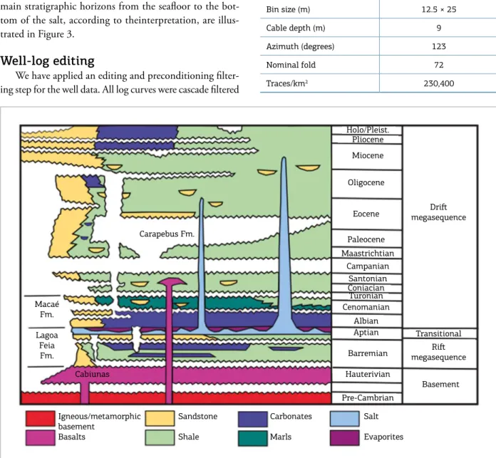
he sedimentary section of the Campos Basin can be grouped into three mega-sequences associated to the fol-lowing tectonic development stages: rift, transitional and drift (Fig. 2).
The Barremian lacustrine sediments of Lagoa Feia Formation overlie the Hauterivian Cabiu´nas basalts (120– 130 Ma); these basalts represent the economic basement of Campos Basin. he Lagoa Feia sediments are recognized as the most valuable source rocks in the Campos Basin.
he Aptian sequence contains, from base to top: con-glomerates, carbonates and evaporitic rocks deposited during a period of tectonic quiescence. his transitional stage expresses the beginning of the drift phase in which the sediments are correlated with the irst sea-water inlows through the Walvis Ridge (Leyden et al. 1976).
he drift stage commences with a marine mega-sequence characterized by the Albian/Cenomanian shallow-water cal-carenites and calcilutites of Maca´e Formation. he marine Upper Cretaceous to Paleogene deep-water clastic section (Carapebus Formation) is composed of shale, marls and sandstone turbidites, deposited in a period of general tec-tonic quiescence and of continued subsidence. he turbidite systems constitute the most valuable petroleum reservoirs in the Campos Basin (Bruhn et al. 2003). Progradational siliciclastic sequences characterize the Neogene section. In the deep-water of the Campos Basin, the deposition of this mega-sequence was greatly conditioned by salt tecton-ics (Mohriak et al. 1996).
MODEL BUILDING WORKFLOW
of such technique, it is necessary to have a large number of wells in hand, and that these wells should have informa-tion of the entire stratigraphic column to be extrapolated. A relative weakness of that approach is the fact that lateral facies variation between the wells cannot be adequately rep-resented through the simple interpolation.
A second widely used alternative is the construc-tion of the resistivity cube based on a velocity—poros-ity—resistivity petrophysical models available in the lit-erature (Hashin & Shtrikman 1962; Hermance 1979; Werthmu¨ller et al. 2013).
In the present work, we estimate the direct relation-ship between velocity and resistivity, then we use this rela-tion to interpolate and extrapolate the resistivities accom-panying previous stratigraphic knowledge throughout the
study area. To this end, we deined a worklow consisting of seven main stages:
■ Seismic and well-log database;
■ Seismic-well tie;
■ Vp cube;
■ Vp x resistivity relationship;
■ Time to depth conversion;
■ Resistivity cubes;
■ Quality control.
Seismic and well-log database
In late 1996, early 1997, Geco-Prakla collected for Petrobras the 3D seismic data interpreted in this study. he survey area spanned over 720 km (Johann et al., 2009). he survey acquisition parameters are presented in Table 1.
380,000 390,000 400,000 380,000 390,000 400,000
7,530,000 7,520,000 7,510,000
Wells
Bathymetry (m) 1,500
1,250
1,000
750
500
250
0 5,000 m
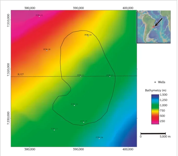
Figure 1. Location map of the seismic dataset at Marlim ield. Coordinates are in UTM, zone 39S. Marlim reservoir outline is shown in the black line. The dashed lines corresponds to the interpreted inline 327. PSW-01 to PSW-09
he Brazilian Petroleum Agency (ANP) made available the public seismic dataset by providing a post-stack time-migrated 3D seismic amplitude cube (Tab. 2), as well as check shots, stratigraphic markers, and composite well logs — density (ρ), sonic (DT), porosity (φ), gamma ray (GR), and hori-zontal resistivity (ρh) of nine wells in the study area (Fig. 1). We have built an integrated database in an open-source seismic platform and loaded the wells’ information (strati-graphic markers and well-log curves), the dip-steering (DS) iltered seismic data and the main stratigraphic horizons interpreted by Nascimento et al. (2014). hose authors have shown that the DS iltered data, in which random spuri-ous noises were attenuated, highlight the main relections related to stratigraphy and therefore they would be more amenable to interpretation.
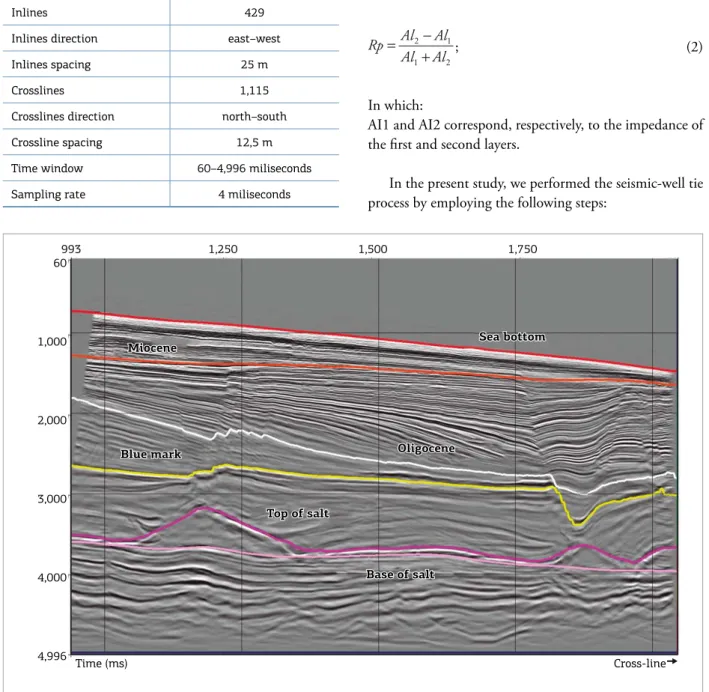
he high quality of the iltered seismic data and the six main stratigraphic horizons from the sealoor to the bot-tom of the salt, according to theinterpretation, are illus-trated in Figure 3.
Well-log editing
We have applied an editing and preconditioning ilter-ing step for the well data. All log curves were cascade iltered
Salt
Evaporites Macaé
Fm.
Lagoa Feia Fm.
Carapebus Fm.
Cabiunas
Holo/Pleist. Pliocene
Miocene
Oligocene
Eocene
Paleocene Maastrichtian
Campanian Santonian Coniacian
Turonian Cenomanian
Albian Aptian
Barremian
Hauterivian
Pre-Cambrian
Driſt
megasequence
Transitional
Riſt
megasequence
Basement
Igneous/metamorphic basement
Basalts
Sandstone
Shale
Carbonates
Marls
Figure 2. Simpliied stratigraphic chart of the Campos Basin, modiied from Guardado et al. (2000). Table 1. Seismic acquisition parameters.
1997 Acquisition
Area (km2) 720
Number of cables 6
Spreads (ofset, m) 0-148-3535.5
Channels/cable 288
Shot point interval (m) 25
Receiver interval (m) 12.5
Cable interval (m) 50
Sample rate (ms) 1
Bin size (m) 12.5 × 25
Cable depth (m) 9
Azimuth (degrees) 123
Nominal fold 72
Traces/km2 230,400
noise, and to bring the log information closer to the seis-mic resolution.
We calculated the Vp logs from the sonic curves by using the Vp = 1/DT relation. Sequentially, we computed the acoustic impedance (AI) logs from (Vp) and density logs.
Seismic-well tie
Well ties are an essential part of the interpreter’s job. he major goal is to correlate the stratigraphic markers described in the wells with the seismic relections aiming
to provide a correct identiication of the horizons to pick. Getting a well tie is quite simple: synthetic seismograms cal-culated from well-log curves are matched to the actual seis-mic traces, and the features of the well in the depth domain are correlated to the seismic data in the time domain.
Synthetic seismograms are obtained from the convolu-tion of the relectivity series in time with a wavelet repre-senting the seismic source. Frequently interpreters extract that wavelet from the seismic data (White & Simm 2003).
he acoustic impedance (AI) and the relectivity (Rp) for any two given media are deined, respectively, by Equations 1 and 2.
AI = Vp × ρ, (1)
2 1 1 2
Al Al Rp
Al Al
− =
+ ; (2)
In which:
AI1 and AI2 correspond, respectively, to the impedance of the irst and second layers.
In the present study, we performed the seismic-well tie process by employing the following steps:
Table 2. 3D cube parameters.
Parameter Quantity
Inlines 429
Inlines direction east–west
Inlines spacing 25 m
Crosslines 1,115
Crosslines direction north–south
Crossline spacing 12,5 m
Time window 60–4,996 miliseconds
Sampling rate 4 miliseconds
Base of salt Miocene
Sea bottom
Blue mark Oligocene
Top of salt
Base of salt
993 1,250 1,500 1,750 60
1,000
2,000
3,000
4,000
4,996
Time (ms) Cross-line
Miocene
Sea bottom
Blue mark Oligocene
Top of salt
■ he seismic traces are bounded by a time window (taper length) and then extracted;
■ Autocorrelation, in the time domain, of the seismic traces within the window deined in the previous step;
■ Employ the direct Fourier transform to obtain the auto-correlation’s frequency spectrum;
■ Calculate the square root of the frequency spectrum’s module and then subtract the zero frequency component;
■ Apply the inverse Fourier transform; the real part of the inverse of the Fourier transform corresponds to extracted zero phase wavelet in time.
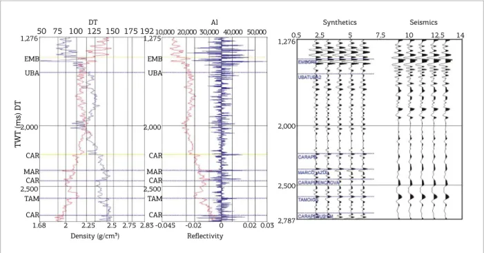
he inal step of the seismic-well tie is given by the asso-ciation between the synthetic seismogram and the seismic data in the vicinity of the well, resulting in a correlation panel for each well, as shown in Figure 4.
Vp cube
The Vp cube was built from the interpolation of the Vp curves along the studied area. At depths beyond the wells’ information, we employed Vp estimates avail-able in the literature.
he interpolation follows the stratigraphic knowledge given by the interpreted horizons along a Horizon Cube by Groot et al. (2010), which consists of a dense 3D set of stratigraphic surfaces associated with a given geological age. Consequently, hundreds of chrono-stratigraphically
correlated horizons, with similar strike and dip, are gener-ated (Qayyum & Smith 2014).
he Horizon Cube was created using six stratigraphic intervals, bounded by the main horizons mapped by Nascimento et al. (2014): Seabed–Miocene, Miocene– Oligocene, Oligocene–Blue Mark, Blue Mark–Top of Salt, Top of Salt–Base of Salt, and Base of Salt–End of Model. he latter one, a 4,976 m time-slice horizon, aiming to rep-resent the base of the model.
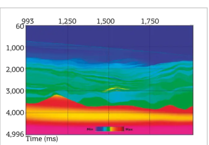
he Horizon Cube is shown in Figure 5A, and the Vp
cube is shown in Figure 5B. We used a single velocity of 4,500 m/s to the salt sequence (Schön 2015), and a regional velocity trend published by Bulhões et al. (2015) to the sed-iments of the Lagoa Feia Group up to the basement rocks.
Vp x resistivity relationship
Background resistivity
Relations between elastic and electrical rock properties have been investigated both theoretically (e.g., Carcione
et al. 2007) and empirically (e.g., Faust 1953; Gomez et al.
2010). Primary applications of such cross-property rela-tionship include illing in data gaps when one property is more readily available than the other. Advanced uses of such relationship include the input of a priori information to reduce ambiguity in the inversion process (Mukerji et al.
2009; Werthmu¨ller et al. 2013).
TWT (ms) DT
50 75 100 125 150 175 192
EMB
UBA
CAR
MAR CAR
TAM
CAR 1,276
2,000
2,500
EMB
UBA
CAR
MAR CAR
TAM
CAR 1,275
2,000
2,500
1,276
2,000
2,500
2,787 1.68 2 2.25 2.5 2.75 2.83
Density (g/cm³)
Al DT
10,000 20,000 30,000 40,000 50,000
-0.045 -0.02 0 0.02 0.03 Reflectivity
Synthetics Seismics
0.5 2.5 5 7.5 10 12.5 14
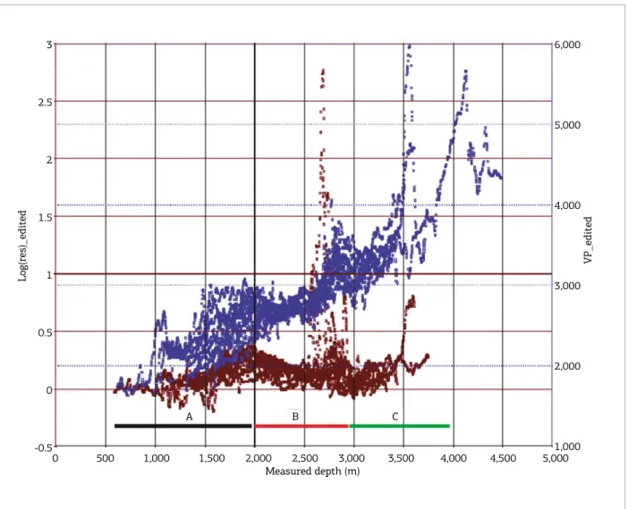
Faust (1953) has shown that both resistivity and veloc-ity behave similarly with increasing depth. To investigate that subject in the studied area, we plotted in Figure 6 the
measured horizontal resistivity (ρh) and Vp at all avail-able wells against depth. As our goal was to deine the background (or regional) resistivity, we did not take into
993 1,250 1,500 1,750 993 1,250 1,500 1,750 60
1,000
2,000
3,000
4,000
4,996
60
1,000
2,000
3,000
4,000
4,996
Time (ms) Cross-line Time (ms) Cross-line
Figure 5. (A) Inline 327 extracted from the Horizon Cube, a stack of chronostratigraphic 3D horizons extracted at inline 317; (B) Vpinterpolated along the inline 327 from the Horizon Cube shown in Figure 5A.
A B C
Log(res)_edited
VP_edited
3
2.5
2
1.5
1
0.5
0
-0.5
0 500 1,000 1,500 2,000 2,500 3,000 3,500 4,000 4,500 5,000 Measured depth (m)
6,000
5,000
4,000
3,000
2,000
1,000
Figure 6. Vp(blue) and resistivity (brown) logs of all nine wells plotted versus depth. A, B, and Care depth intervals herein interpreted.
account the high resistivity values associated with the res-ervoir (average of 70o hm.m).
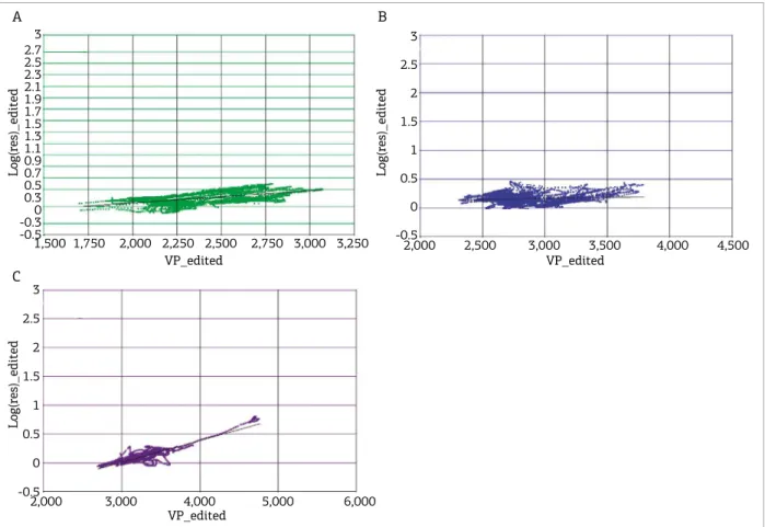
In Figure 6 we have classified three distinct zones: 600–2,000 m (zone A), 2,000–2,900 m (zone B), and depths greater than 2,900 m (zone C). Then, we cal-culated the relationship between log(ρh) and Vp by crossploting these two quantities at each identified A, B, and C depth zones. The crossplots of the respective zones are shown in Figures 7A, 7B and 7C. Hence, by least-squares fitting, we obtained three linear equations (Eqs. 3, 4 and 5) relating the background horizontal resistivity and velocity.
ρh 600−2,000 m = −0.263 + 0.000166 Vp, (3)
ρh 2,000−2,900 m = −0.0683 + 2, 798.10-5Vp, (4)
ρh>2,900 = −0.09 + 0.00037Vp (5) In which ρh 600−2,000 m, ρh 2,000−2,900 m, and ρh
2,900−end represent, respectively, the horizontal resistivity in the range of 1,000–2,000 meters, 2,000–2,900 meters and depths greater than 2,900 meters. At depth zone C,
Log(res)_edited Log(res)_edited
Log(res)_edited
A
C
B
3 2.7 2.5 2.3 2.1 1.9 1.7 1.5 1.3 1.1 0.9 0.7 0.5 0.3 0 -0.3 -0.5
1,500 1,750 2,000 2,250 2,500 2,750 3,000 3,250 VP_edited
VP_edited
VP_edited 3
2.5
2
1.5
1
0.5
0
-0.5
2,000 2,500 3,000 3,500 4,000 4,500
3
2.5
2
1.5
1
0.5
0
-0.5
2,000 3,000 4,000 5,000 6,000
Figure 7. Relations between resistivity and Vpfor all nine wells at three distinct depth intervals (Figure 6): (A) depth interval A; (B) depth interval B; (C) depth interval C.
the exception is the salt sequence (deined by top and base of salt horizons), where we assigned the single value of 1,000 ohm.m (Zerilli et al. 2016).
Anomalous resistivity
The high resistivities associated with the oil-prone Marlim turbidite sands match the anomalous reser-voir values embedded in the low-resistivity regional background of the non-reservoir facies in depth zone b (Eq. 4).
Consequently, it is necessary to distinguish between the reservoir and the non-reservoir facies, and then associate the anomalous resistivity value only to the reservoir facies. To that end, we follow the interpretation of Nascimento
et al. (2014), that described the reservoir facies with the acoustic impedance lower–equal than 5,700 m/s.g/cm3 and
porosity in the 0.26–0.32% range.
To that end, we created an algorithm (Algorithm 1) to identify and assign the Marlim reservoir facies resistivity and distinguish it from the background values. he input are the Vp, porosity and AI cubes.
Time to depth conversion
here are several methods for the time-depth (T–D) conversion. However, one can distinguish two main cate-gories (Etris et al. 2001):
■ Direct conversion;
■ Velocity modeling.
We have followed the second option, by building an inter-val velocity model based on the well-log ties curves. hose were smoothed and interpolated along the studied area using the Horizon Cube. For the salt and subsalt sequences, we have applied, respectively, a constant 4,550 m/s interval velocity, and a velocity trend based on the studies of Bulhões et al. (2015).
he T–D conversion was made following two main steps, First of all, we did it only at seismic sections crossing the wells as a QC. Depth converted horizons were checked against the position of their correspondent stratigraphic marker at the wells. he inal interval velocity model is shown in Figure 8.
In the second step, we used the 3D interval velocity model to convert to depth all the available property cubes:
ρh, ρv , Vp, porosity and acoustic impedance and also the main stratigraphic horizons.
RESISTIVITY CUBES
To compute the ρh cube from the Vp cube, we devel-oped a second algorithm (Algorithm 2). he input is the
Vp, porosity and acoustic impedance cubes, but also some of the stratigraphic horizons.
Algorithm 2 implements both the background resistivi-ties and incorporate algorithm 1 to distinguish between the reservoir and non-reservoir facies. We settled a stratigraphic window between the Top of Oligocene and BlueMark hori-zons (depth interval between 2,000–2,900m). BlueMark, a maximum lood surface of the Eo-Oligocene, is considered the base of the turbiditic reservoirs (Gamboa et al. 1986).
We used an anisotropic ratio (ρv /ρh) = 2.5 to calculate Marlim–R3D vertical resistivity cube from the horizontal resistivity cube (Park et al. 2015). hat ratio was applied to the whole sedimentary section, except for the salt bodies that were handled as isotropic layers.
QUALITY CONTROL
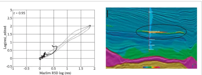
To perform the quality control (QC) of the converted resistivity cube, we crossplot the recovered values against the measured resistivity in wells. hen we ind a linear relation-ship by least-squares itting, which its both data to a spe-ciic correlation coeicient. hat coeicient stands between 0 and 1 (0 to 100%).
For the sake of brevity, we show in Figure 9 the results for only one well: PS-W-01, which correlation coeicient is 0.95, i.e., a 95% agreement between the modeled and measured resistivity was obtained.
As can be seen in Figure 9, the resistive turbidite sand-stones that form the reservoir of the Marlim Field are prop-erly outlined at depth, with top and base coinciding with the well information.
Figure 10 shows the vertical resistivity extracted along Top of Marlim horizon slice. he Marlim reservoir facies emerges as a high resistivity body embedded in a low-resistivity input: Vp, φ and AI cubes
output: Resistivity of Marlim reservoirs
1 initialization;
2 if AI ≤ 5,700 then
3 if 0.26 ≤ φ ≤ 0.32 then ρhmarlim = log10(70);
4 else ρhmarlim = ρh200-2900m; 5 end
Algorithm 1. Marlim reservoir resistivities.
input: Vp, φ, AI cubes and horizons in depth domain
output: Marlim R3D horizontal resistivity cube
1 initialization;
2 if depth ≤ 2,000 m then
3 ρh= ρh600−2,000 m = −0.263 + 0.000166Vp; 4 if 2,000 ≤ depth ≤ 2,900 then
ρh = ρh2,000−2,900 m = −0.0683 + 0.000002798Vp; 5 if Top of Marlim < depth < Blue Mark then execute
algorithm 1;
// distinguish between reservoir and non-reservoir resistivities
6 if Top of Salt < depth < Base of Salt then ρh = log10(1,000);
// Salt resistivity
7 if depth ≥ 2,900 then ρh = ρh>2900 = −0.09 + 0.00037Vp
Algorithm 2. Calculation of the horizontal resistivity in the depth domain. Topof Marlim, Blue Mark, Top of Salt and Base of Salt are stratigraphic horizons. Time (ms)
993 1,250 1,500 1,750 60
1,000
2,000
3,000
4,000
4,996
3
2.5
2
1.5
1
0.5
0
-0.5 r = 0.95
Log(res)_edited
-1 -0.5 0 0.5 1 1.5 2 Marlim R3D log (res)
Figure 9. Right panel: crossplot between recovered ρh versus measured resistivity (ILD log) at PS-W-01 well.
Let panel: comparison between the recovered ρhalong an arbitrary section and the measured resistivity log
at PS-W-01 well.
Figure 10. Map of the vertical resistivity distribution along a horizon at the top of Marlim reservoir. PSW-01 to PSW-09 are the available wells. The Marlim turbidites (clean sandstones) are clearly highlighted as high-resistivity bodies. Shale and shaly sand (non-reservoir) facies show lower ressitivity values.
380,000 390,000 400,000 380,000 390,000 400,000
7,530,000 7,520,000 7,510,000
Wells
Log(Rv – ohm.m) 3.0 2.5 2.0 1.5 1.0 0.5 0.0 -0.5
background. Rather than a single resistivity body, as com-monly pictured in most of the available resistivity models, including the SEAM-Phase I model, Marlim R3D exhib-its a complex resistivity pattern. hat is in agreement with the expected geological complexity of the turbidite bodies.
CONCLUSIONS
We present Marlim R3D, a realistic geoelectric model for CSEM simulations. he Marlim R3D aims to be a bench-mark model for studies of turbiditic reservoirs.
he Marlim R3D model comprises a data set consisting of ρh and ρv cubes in SEG–Y format, the six stratigraphic horizons, and Vp, ρh and ρv , well-logs extracted from Marlim R3D in the position of nine wells. hese well-logs aim to serve as a quality control of modeling and inversions studies using Marlim R3D.
hese cubes are being made freely available to the gen-eral public on the Zenodo.
he cube is rendered in SGY format with data distrib-uted along 75 × 25 × 5 m cells. We are currently develop-ing a detailed 3D CSEM inite–diference forward study
to generate an oicial CSEM dataset for Marlim R3D. he full dataset will be soon delivered to general public at the Zenodo platform.
Although primarily conceived to be a CSEM refer-ence model, Marlim R3D can also be used to simulate responses to any electromagnetic method such as marine magnetotellurics, surface-to-borehole EM, or even cross-well-EM studies.
ACKNOWLEGMENTS
We thank dGB Earth Sciences for making freely available the open-source seismic interpretation software OpendTect. We acknowledge Laboratório de Geofísica Exploratória at Universidade do Estado do Rio de Janeiro (LAGEX/UERJ) for making available its computational park. P. Menezes thanks the support provided by research grant from the Brazilian National Council for Scientiic and Technological Development (CNPq). Data set made available under the support of the CNPq Project coordinated by A. Evsukof. We also thank the additional support by CNPq project no. 470742/2011-9.
Bruhn C.H.L., Gomes J.A.T., Del Lucchese Jr.C., Johann P.R.S. 2003. Campos basin: Reservoir characterization and management-historical overview and future challenges. In: Ofshore Technology Conference. Rio de Janeiro, p. 14
Bulhões F.C., Formento C.D.R., Lyrio J.C.O., Amorim G.A., Ferreira G.D., Pereira E.S., Castro R.F. 2015. Geostatistical 3d density modeling: Integrating seismic velocity and well logs. In: 14th International Congress of the Brazilian Geophysical Society & EXPOGEF. Rio de Janeiro, Brazilian Geophysical Society, p. 272-277.
Carcione J.M., Ursin B., Nordskag J.I. 2007. Cross-property relations be- tween electrical conductivity and the seismic velocity of rocks. Geophysics, 72(5):E193-E204.
Carvalho B.R. & Menezes P.T.L. 2017. Marlim R3D - A Realistic Model For Mcsem Simulation. Zenodo, https://doi.org/10.5281/ zenodo.400233.
Constable S. & Cox C.S. 1996. Marine controlled-source electromagnetic sounding: 2. the Pegasus experiment. Journal of Geophysical Research, 101(B3):5519-5530.
Constable S. & Srnka L.J. 2007. An introduction to marine controlled-source electromagnetic methods for hydrocarbon exploration. Geophysics, 72(2):WA3-WA12.
Edwards N. 2005. Marine controlled source electromagnetics: Principles, methodologies, future commercial applications. Surveys in Geophysics, 26(6):675-700.
Etris E.L., Crabtree N.J., Dewar J. 2001. True depth con- version: More than a pretty picture. Canadian Society of Exploration Geophysicists,
26(9):11-22.
Evans R.L., Sinha M.C., Constable S.C., Unsworth M.J. 1994. On the
electrical nature of the axial melt zone at 13° N on the East Paciic
Rise. Journal of Geophysical Research, 99(B1):577-588.
Faust L.Y. 1953. A velocity function including lithologic variation. Geophysics, 18(2):271-288.
Fehler M. 2009. SEAM phase I progress report: “classic” data sets. The Leading Edge, 28(10):1178-1181.
Gamboa L., Esteves F., Shimabukuro S., Carminatti M., Peres W., Souza Cruz C. 1986. Evidˆencias de varia¸c˜oes de nivel do mar durante o oligoceno e suas implica¸c˜oes faciol´ogicas. In: SBG, Congresso Brasileiro de Geologia, p. 8-22.
Gomez C.T., Dvorkin J., Vanorio T. 2010. Laboratory measurements of porosity, permeability, resistivity, and velocity on Fontainebleau sandstones. Geophysics, 75(6):E191-E204.
Groot P., Huck A., Bruin G., Hemstra N., Bedford J. 2010. The horizon cube: A step change in seismic interpretation! The Leading Edge,
29(9):1048-1055.
Guardado L.R., Spadini A.R., Brand˜ao J.S.L., Mello M.R. 2000. Petroleum system of the Campos Basin, Brazil. American As- sociation of Petroleum Geologists, 317-324.
Hashin Z. & Shtrikman S. 1962. A variational approach to the theory of the efective magnetic permeability of multiphase materials. Journal of Applied Physics, 33:3125-3131.
Hermance J.F. 1979. The electrical conductivity of materials containing partial melt: A simple model from Archie’s law. Geophysical Research Letters, 6(7):613-616.
Johann P., Sansonowski R., Oliveira R., Bampi D. 2009. 4D seismic in a
heavy-oil, turbidite reservoir ofshore Brazil. The Leading Edge, 28(6):718-729. Leyden R., Asmus H., Zembruscki S., Bryan G. 1976. South Atlantic diapiric structures. AAPG Bulletin, 60(2):196-212.
MacGregor L. & Tomlinson J. 2014. Marine controlled-source electromagnetic methods in the hydrocarbon industry: A tutorial on method and practice. Interpretation, 2(3):SH13-SH32.
Mohriak W.U., Macedo J.M., Castellani R.T. 1996. Salt tectonics and structural styles in the deep-water province of the Cabo Frio region, Rio de Janeiro, Brazil. The American Association of Petroleum Geologists Memoir .
Mukerji T., Mavko G., Gomez C. 2009. Cross-property rock physics relations for estimating low-frequency seismic impedance trends from electromagnetic resistivity data. The Leading Edge, 28(1):94-97. Nascimento T.M., Menezes P.T.L., Braga I.L. 2014. High-resolution acoustic impedance inversion to characterize turbidites at Marlim Field, Campos Basin, Brazil. Interpretation, 2(3):T143-T153. Park J., Viken I., Menezes P.T.L., Filho C.E.B.L., Dabbadia M.R.A. 2015. Feasibility of borehole-surface EM for CO2 injection monitoring with a
synthetic-ield case. In: SEG Technical Program Expanded Abstracts. Society of Exploration Geophysicists, p. 1033-1038.
Qayyum F. & Smith D. 2014. Integrated sequence stratigraphy using trend logs and densely mapped seismic data. First Break,
32(12):75-84.
Schön J.H. 2015. Physical properties of rocks: Fundamentals and principles of petrophysics. volume 65, Elsevier, 497p.
Tseng H.W., Stalnaker J., MacGregor L.M., Ackermann R.V. 2015. Multi-dimensional analyses of the SEAM controlled source electromagnetic data – the story of a blind test of interpretation workflows. Geophysical Prospecting, 63(6): 1383-1402.
Werthmu¨ller D., Ziolkowski A., Wright D. 2013. Background resistivity model from seismic velocities. Geophysics, 78(4):E213-E223.
White R.E. & Simm R. 2003. Tutorial: Good practice in well ties. First Break, 21.
Zerilli A., Buonora M.P., Menezes P.T.L., Labruzzo T., Mar¸cal A.J., Crepaldi J.L.S. 2016. Broadband marine controlled-source electromagnetic for subsalt and around salt exploration. Interpretation, 4(4):T521-T531.
