This is an open-acacaess articalae eisrriburee uneer rhe rerms of rhe rreative rommons
Attribution Licaense nonreh httph//wwwwww scaielao br/scaielao
phpcscaripr=scai_arttexrppie=o679e-982520690004005e4plang=enpnrm=iso Acaesso emh 67 jan 2068
REnERÊNrIA
RIBEIRO, Paulao Marcaelao Vieira; PEDROoO, Lineu mosé Dynamica response of Dam-Reservoir sysremsh
revieww ane a semi-analayticaala proposala Latin Americaan Jourinal o oolcsm ans otdriuatduriem, Rio ee
maneiro, v 64, n 4, p 5e4-762, mar 2069 Disponívela emh <httph//wwwwww scaielao br/scaielao phpc
scaripr=scai_arttexrppie=o679e-982520690004005e4plang=enpnrm=iso> Acaesso emh 67 jan 2068
eoih httph//ex eoi org/60 65e0/679e-98253500
Abstract
This paper presents a review of current techniques employed for dynamic analysis of concrete gravity dams under seismic action. Traditional procedures applied in design bureaus, such as the Pseudo-Static method, often neglect structural dynamic properties, as well as ground amplification effects. A practical alternative arises with the Pseudo-Dynamic method, which considers a simpli-fied spectrum response in the fundamental mode. The authors propose a self-contained development and detailed examples of this latter method, including a comparison with finite element models using transient response of fluid-structure systems. It is verified that application of the traditional procedure should be done care-fully and limited to extremely rigid dams. On the other hand, the proposed development is straightforward and in agreement with finite element results for general cases where dam flexibility plays an important role.
Keywords
concrete, gravity dams, dynamic, pseudo-dynamic, seismic, design
Dynamic Response of Dam-Reservoir Systems:
Review and a Semi-Analytical Proposal
1 INTRODUCTION
The last few years in Brazil have indicated a growing interest in national engineering for earth-quake-resistant design. The first design code dedicated exclusively to this type of analysis was ap-proved in 2006 (NBR15421, 2006). However, computation of earthquake effects in design of special structures, such as concrete dams, aqueducts and nuclear power plants, has being done for decades, although in a simplified form. Noteworthy is the Pseudo-Static Method (or Seismic Coefficient Method), where the structural mass is treated as an accelerated rigid body. In this case, the seismic coefficient matches exactly the structural acceleration, which is usually taken as a fraction of gravi-tational acceleration. Due to its simplistic nature, the Pseudo-Static procedure is still widely used in the seismic analysis of structures, although condemned by international codes (FERC, 2002). This type of analysis is usually defined as traditional procedure for seismic design.
Paulo Marcelo Vieira Ribeiro a Lineu José Pedroso b
a
Universidade Federal de Pernambuco. Departamento de Engenharia Civil. Recife-PE, Brazil.
b
Universidade de Brasília.
Departamento de Engenharia Civil e Ambiental. Brasília-DF, Brazil. [email protected]
http://dx.doi.org/10.1590/1679-78253500 Received 08.11.2016
Accepted 26.01.2017 Available online 09.02.2017
In general, the Pseudo-Static Method will produce the same results for any given structure with equal mass. That is, both structures will be subjected to the same seismic loading and no considera-tion will be made in relaconsidera-tion to the dynamic properties of both (such as vibraconsidera-tion period, for exam-ple). As a consequence, dynamic amplification effects are neglected and the response is valid only for infinitely rigid structures.
The traditional procedure is increasingly destined to oblivion. The main reason is the absence of dynamic properties of the structure. In the specific case of concrete dams two major hypotheses govern the problem: (i) fluid is treated as incompressible and (ii) the dam moves with uniform ac-celeration along its height. The method basis comes from the classic work of Westergaard (1933), published almost 80 years ago. The last decades were marked by new calculation procedures and additional contributions to the legacy of Westergaard. These new procedures, such as the Pseudo-Dynamic Method, require additional complexity in computation of earthquake forces. On the other hand, provide a more coherent representation of dynamic effects.
Alerts regarding the limitations of the traditional procedure are not new. The pioneer work done by Chopra (1978) pointed practical alternatives to the Seismic Coefficient Method. This same au-thor made a series of works in this area with numerous contributions, such as: interaction effects of dam-reservoir-foundation system (Fenves and Chopra, 1984) and participation of higher modes in the dynamic response (Fenves and Chopra, 1985). Another prominent work in a similar line is the one given by Rashed(1983), who presented dam-reservoir interaction results for 2D and 3D prob-lems. Lee and Tsai (1991) developed a closed form time domain analysis using a simplified geometry of the monolith. The common point of all the works cited above is the wave equation governing the fluid domain. Therefore, dam-reservoir interaction has been treated as a typical vibroacoustic prob-lem, with development of closed form solutions for the fluid domain, followed by added mass effects applied to the dam.
Many authors have also researched analytical solutions for a wide range of vibroacoustic prob-lems. Pretlove (1965) analyzed the interaction between a flexible panel and a rectangular cavity. Xing et al. (1997) and Miquel and Bouaanani (2014) focused on the interaction of beam-fluid sys-tems. Hong and Kim (1995a,b) developed a general procedure using in-vacuum vibration modes (or dry modes) for general 2D and 3D vibroacoustic problems.
In Brazil, the impact of dam-reservoir related papers in academia was almost zero until the mid-2000’s, where the initiative of the Dynamics and Fluid-Structure Interaction Group (GDFE) at University of Brasilia allowed the dissemination of related work in scientific publications with major results achieved by Ribeiro (2006), Silva (2007) and Ribeiro (2010a), among others.
Recent research trends for this problem are currently focused on finding simplified procedures that avoid cumbersome solutions using finite element fluid-structure models and do not suffer from overall limitations of past procedures, devoted mainly to analytical contributions. A work done by Miquel and Bouaanani (2010) points at this direction, using previous developed procedures as a basis for semi-analytical interventions, where previous knowledge is combined with numerical model results. This research follows a similar path. However, described expressions are a result from the last ten years of GDFE research and strongly based on Ribeiro and Pedroso (2010) studies for vi-broacoustic problems. Therefore, are self-contained and completely independent from previous
de-velopments. Although presented for dam-reservoir interaction, this proposal can be also extended for general vibroacoustic problems in 2D and 3D.
In the scope of a literature review, this paper presents a comparative study of: (I) the Pseudo-Static Method; (II) the Pseudo-Dynamic Method and (III) structural dynamic analyses using finite element fluid-structure models. Results show that the seismic coefficient hypothesis is limited to very specific situations where the dam vibration period is virtually nil. Finally, we propose a self-contained development to properly represent the dynamic forces acting on a concrete gravity dam.
2 PSEUDO-STATIC OR SEISMIC COEFFICIENT PROCEDURE
Westergaard (1933) pioneered the approach to the dam-reservoir interaction problem. The basic idea of his procedure was to calculate the hydrodynamic pressure produced by the reservoir due to a horizontal acceleration of the structure (Figure 1a). In this case, the pressure distribution p1(x,y) is obtained by solving the Laplace equation for the boundary conditions shown in Figure 1b, which corresponds to an accelerated rigid boundary in an incompressible reservoir with infinite longitudi-nal length.
Figure 1: (a)Dam-reservoir interaction problem; (b) governing equation and boundary conditions for fluid domain. The solution of the problem illustrated in Figure 1b leads to the equation of hydrodynamic pressures at the dam-reservoir interface, which represent the forces exerted by the fluid along the dam´s upstream face. In this case, the solution results in an infinite series given by Equations (1) and (2).
(
)
( )
(
)
1 1 2 1 2 1 0, n f n n n U p y cos y H r k k + ¥ = -= å
(1)(
2 1)
; 1,2, 3 2 n n n H p k = - = ¼ (2)Alternatively, Westergaard (1933) established a simplified expression given by Equation (3):
(
)
2 1 West. 0.543 7 0, 1 0.583 8 f y p y U H H r æç ö÷ = çç - ÷÷÷ è ø (3) 0, ground acceleration , 0 → ∞ 0 0 0 reservoir rigid boundary Hwith rf defining the fluid specific mass.
In addition to hydrodynamic effects, there are also actions arising from the structural inertia. However, this calculation is greatly simplified by the assumption of a uniform acceleration along dam’s height. Therefore, seismic actions (inertia and hydrodynamic forces) in the traditional proce-dure are set according to the prescribed ground acceleration, which in practice is defined as a seis-mic coefficient, providing and alternative definition for the Pseudo Static Method. The seisseis-mic coef-ficient value is defined depending on the local seismicity. In current Brazilian practice this term varies between 0.05-0.10g, where g represents the acceleration of gravity. According Priscu (1985), the main disadvantages of this procedure arise from: (i) neglecting structural elasticity, (ii) assum-ing uniform foundation acceleration over time, (iii) neglectassum-ing structural dampassum-ing and (iv) structur-al dynamic response.
Chopra and Chakrabarti (1971) investigated the accident at Koyna Dam (India, 1967, during an earthquake of magnitude 6.5), where the dam was designed with a seismic coefficient of 0.05g. The structure showed important cracks in upstream and downstream faces, as well as in locations near camber changes. A sudden break did not occur and no leakage was detected, but the damage was severe, leading to construction of buttresses on the downstream (CEE, 1990). This event led to a more detailed study of the existing dynamic interaction in this type of problem and has raised questions about the validity of the traditional design procedure. Since then, several studies have been carried out, always with the intention of modernizing calculation procedures.
3 PSEUDO-DYNAMIC METHOD (RESPONSE SPECTRUM ANALYSIS)
3.1 Method Basis
The first step towards consideration of dynamic response due to earthquake excitation is a response spectrum analysis. This procedure, widely used in seismic analysis of structures (Clough and Pen-zien, 1993), is outlined in Figure 2. When applied to dams, an additional designation comes to the procedure: Pseudo-Dynamic Method (Lecrerc et al., 2000). The objective is the evaluation of the maximum structural response when the dam is subjected to a seismic record. Although a complete response over time or frequency is possible (analysis in the time or frequency domains, respectively), in most practical situations just a maximum response ( ) is required. Response spectra are built for each specific event (seismic record), and in some cases, defined by artificial functions. The struc-tural system is associated with a discrete model of a single degree of freedom and the maximum response is calculated based on the undamped vibration period (T) and the corresponding structural damping ratio (ξ).
In general, seismic response spectrum analysis involves the following outputs: maximum relative displacement ( ), pseudo velocity ( ) and pseudo acceleration ( ). The ‘pseudo’ prefixes are derived from simplifications in computation of spectral velocity and acceleration, making them dis-tinct from the actual values of relative speed and total acceleration, respectively. These three quan-tities have among themselves relations indicated in Equation (4), where ω indicates the undamped natural frequency of the system.
; pv d pa pv S S S wS w = = (4a,b)
Figure 2: Response spectrum generation scheme (adapted from [17]).
For a given ground acceleration record ( ), response spectrum construction follows with initial computation of the spectral pseudo-velocity. It is noted that (Clough and Penzien, 1993):
( )
( )(
)
0 t t pv max S U t e-xw -t senw t t td é ù ê ú = ê - ú ê ú ëò
û (5)with denoting time.
After evaluation of the maximum values of Equation (5), relative displacements and pseudo ac-celerations are computed and the response spectra can be built. Most design codes provide prede-fined spectra for earthquake-resistant design (such as Brazilian standard NBR15421, for example). It is worth noting the existence of free software that can perform the previous described tasks for an arbitrary seismic record. SeismoSignal is an example, and will be used in the analyses of this work.
3.2 Pseudo-Dynamic Method
The classic work done by Chopra (1978) defined an additional step in seismic analysis practice for concrete gravity dams, which was previously limited to the traditional design procedure (Pseudo-Static Method). This new approach emerged as an alternative to dynamic analyses, where the use of a computer is required. It is a simplified version of the response spectrum analysis, with evaluation of the maximum structural response in the fundamental mode. On the Pseudo Static Method, the dam is supposed rigid. On the other hand, the Pseudo Dynamic Method now considers a flexible dam interacting with a compressible fluid in the reservoir. Inertial forces and hydrodynamic pres-sures now depend on two movement components: translational and relative.
The scheme shown in Figure 3 reveals that this procedure involves a contribution neglected in the traditional procedure: relative movement. That is, the Pseudo Static Method is a particular case of the Pseudo Dynamic Method, where the relative component vanishes. This simple observation
rMAX
Discrete Systems
Response Spectrum Procedure T2 T1 damping increment T Response Spectrum Seismic record
Single degree of freedom T3
serves as a warning against scenarios where the traditional procedure is employed. In fact, for flexi-ble structures, structural response can greatly amplify ground acceleration values, with relative component governing the problem.
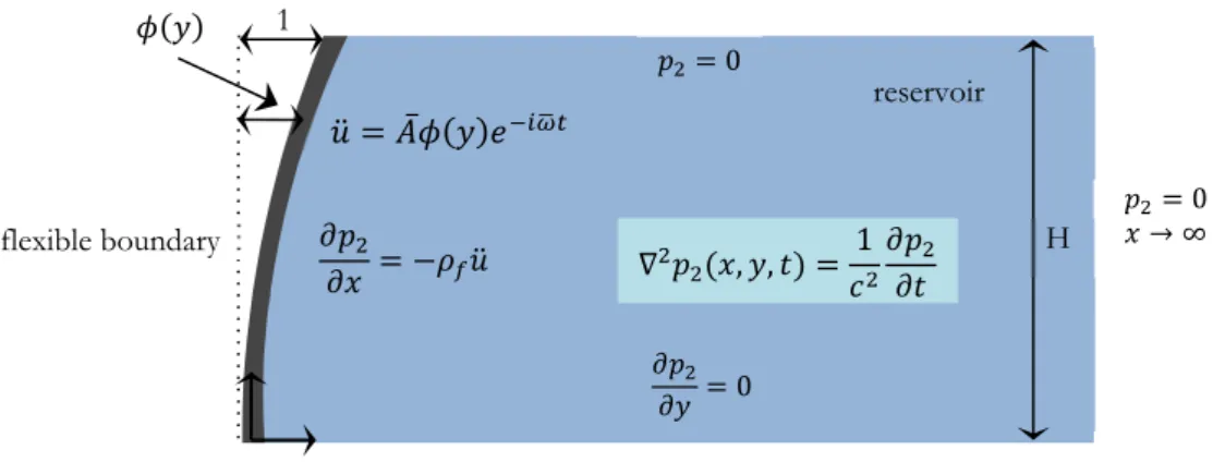
Evaluation of hydrodynamic pressures on Figure 3a is developed according to the scheme illus-trated in Figure 1b, resulting in solutions given by Equations (1) and (2). For Figure 3b an addi-tional scheme is employed, shown in Figure 4, with a vibrating boundary in a continuous governed by the 2D wave equation (and later reduced to Helmholtz equation with frequency w). In this case, the boundary is called flexible (in contrast to the rigid boundary in the traditional procedure) and normalized at y =H
.
The term A denotes boundary acceleration amplitude at this latter position.Figure 3: Translational (a) and relative (b) movement components for the Pseudo-Dynamic Method.
Figure 4: Governing equations and boundary conditions for the relative component.
The problem shown in Figure 4 has been extensively discussed in Silva (2007) and Ribeiro (2010) works. The frequency domain solution of hydrodynamic pressures at the interface is given by:
(
)
( ) (
)
(
)
2 1 0 2 1 0, , ˆ H f n n n n A p y y cos y dy cos y H r w f k k a ¥ = =å
ò
(6) with: translational relative 0, 0, , , 1 0 → ∞ ̅ 0 0 1 flexible boundary reservoir H( )
2 2 2 ˆn n c w a = k - (7)(
2 1)
; 1,2, 3 2 n n n H p k = - = ¼ (8)and
c
defining the sound velocity in the medium (in water, approximately 1500 m/s).Once the fluid components are known, the next step consists in construction of dynamic equilib-rium equation of the fundamental mode of the system. In this case:
(
M +Mf X t) ( )
+CX t( )
+KX t( )
= -U t L( )
ëé+Nùû (9)Parameters M, C, K and L respectively indicate: generalized structural mass, damping,
stiff-ness and seismic participation factor of the fundamental mode of the uncoupled structure. And the term X denotes the relative displacement of the prescribed generalized coordinate at the dam´s crest. Fluid interaction effects are represented by terms Mf and N
,
related to added mass and additional seismic excitation components, respectively. Figure 5 helps to identify these terms.Figure 5: Structural (a) and fluid (b) generalized parameters.
Two distinct paths are provided for evaluation of the generalized parameters shown in Figure 5a: (i) a modal analysis of the structure in any basic finite element software, (ii) simplified expres-sions such as the ones provided by Chopra (1978). Additional parameters produced by the fluid, indicated in Figure 5b, are described by Equations (10) and (12).
(
)
( )
2 0 0, , H p y Mf y dy A w f =ò
(10)with the fundamental mode coupled frequency
achieved with solution of (11):(
)
2 0
K -w M +Mf = (11)
Structural Generalized Parameters
(a)
Fundamental Mode
(b)
relative
Fluid Generalized Parameters
Equation (11) is simple in nature, but involves cumbersome term Mf . This term is given by a definite integral of p2, which involves an infinite series and it is a function of w. Therefore, evalua-tion of the fundamental mode coupled frequency is achieved with a transcendental equaevalua-tion for w
.
Once obtained, this parameter can be replaced in (10) allowing the computation of Mf
.
(
)
( )
1 0 0, H p y N y dy A f =ò
(12)Once the generalized parameters are computed, the analysis of the maximum dynamic response of Equation (9) is performed with the aid of a seismic response spectrum. The goal is to calculate the equivalent seismic forces, which are then applied to an equivalent static analysis. This is the essence of Pseudo-Dynamic Method, where static loadings replace the dynamic effects produced by seismic excitation. One should note that this type of analysis, as its name indicates, does not corre-spond to a true dynamic analysis, since the time varying nature of the response is neglected (Priscu, 1985).
For empty reservoir scenario the equivalent static load is obtained from (13)-(15):
( )
( ) ( )
2 e s d L y m y y S M q = f éêêw ùúú ë û (13) 2 T p w = (14) K M w = (15)where
m
s defines the mass distribution along the dam´s height and T is the fundamental period ofthe structure.
For operational reservoir level scenario:
( )
{
( ) ( )
( )
}
2 r r s f d r q y m y y m y L S M f éêw ùú = + ê ú ë û (16) 2 T p w = (17) r K M w = (18) r L =L+N (19)r
M =M +Mf (20) where
T
denotes the fundamental period of the dam-reservoir system. Additionally,mfcorrespondsto inertial effects produced by the fluid with expression defined by:
( )
2(
0, ,)
f p y m y A w = (21)In summary, the roadmap for application of the Pseudo-Dynamic Method is divided into three basic steps: (I) evaluation of structural generalized parameters; (II) computation of the coupled vibration period
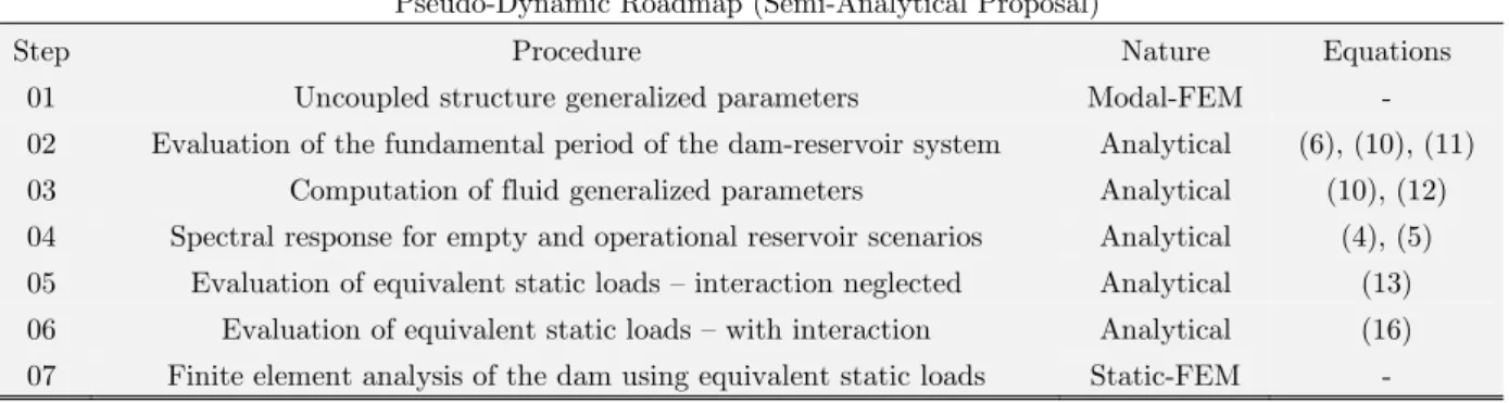
and further evaluation of fluid generalized parameters; (III) computation of spectral response, equivalent static loads and subsequent stress and stability analysis. Stress analy-sis can be performed using the equivalent static loads in a finite element model or by application of those to a simplified method of stress evaluation, such as the Gravity Method (USBR, 1976). The first approach will be adopted in this paper. Table 1 summarizes the current proposal.Pseudo-Dynamic Roadmap (Semi-Analytical Proposal)
Step Procedure Nature Equations
01 Uncoupled structure generalized parameters Modal-FEM -
02 Evaluation of the fundamental period of the dam-reservoir system Analytical (6), (10), (11)
03 Computation of fluid generalized parameters Analytical (10), (12)
04 Spectral response for empty and operational reservoir scenarios Analytical (4), (5)
05 Evaluation of equivalent static loads – interaction neglected Analytical (13)
06 Evaluation of equivalent static loads – with interaction Analytical (16)
07 Finite element analysis of the dam using equivalent static loads Static-FEM -
Table 1: Summary of Pseudo-Dynamic Method.
4 FINITE ELEMENT FLUID-STRUCTURE MODELS
The numerical solution of a dam-reservoir interaction problem requires proper discretization of 02 subdomains: fluid and structure. In this paper, the solid is governed by the 2D elasticity equation, while the fluid is represented by the wave equation. Usually a transient analysis involves high com-putational cost. For this reason, it is common to use a spectral analysis, as indicated in Section 3. These numerical models serve as reference solutions for the simplified procedures, indicating wheth-er the adopted hypotheses are valid or not. An initial step is given by modal evaluation of the dam-reservoir system. In the latter case the wave equation is replaced by the Helmholtz equation.
In free vibration, the fluid-structure system is governed by the eigenvalue problem given by (22). This is a convenient expression for viewing both domains, as well as coupling terms.
{ }
{ }
2 0 0 0 0 s s ss sf M K F d A w F B p æé é ù é ù ù é é ù ù ö÷ìï üï ì üï ï çêë û ë ûú êë û ú÷ï ï ï ï ç - ÷í ý=í ý çê é ù ú êé ù é ù ïú÷÷ ï ï ï çèêë ë û úû êëë û ë ûú ïûøî ïþ ï ïî þ (22)In this case, [Ks] and [M ]s represent the stiffness and mass matrices of the structural domain. The same reasoning is also applied for fluid matrices [A] and [B], related to the fluid domain with interaction effects neglected (uncoupled cavity). Finally, éëFssùû and éëFsfùû are defined as coupling matrices for displacement (
{ }
d ) and pressure ({ }
p ) degrees of freedom.Equivalence with the classical representation of structural dynamics allows the following gener-alization for a transient analysis:
{ }
{ }
{ }
{ }
{ }
{ }
{ }
0 0 0 0 0 s s s ss sf f M d C d K F d f A p p p F B C é éë ûù ùïìï üïï é éë ùû ùìïï ïïü é éë ù éû ë ù ù ìû ïï üïï ïìï üïï ê úí ý+ê úí ý+ê úí ý=í ý êé ù é ù ïú ï ê é ùúï ï êê é ù úúï ï ï ï êë û ë ûúïî þï ê ë ûúîï þï ë ë û û îï þï îï ïþ ë û ë û (23)Where éëCsùû and éëCf ùû correspond to damping matrices for the structure and fluid, respectively. The action of external forces in the structure is represented by vector
{ }
f .5 ANALYSIS AND RESULTS
This section presents a comparative study of principal stresses in two concrete gravity dams by three different approaches: (i) Pseudo-Static Method (ii) Pseudo-Dynamic Method and (iii) Finite Element Method fluid-structure transient analysis (treated as reference value).
5.1 Analyzed geometries and material properties
Two distinct types of geometries were analyzed: Dam 1 is a short dam and Dam 2 is a moderate height structure. The geometric properties of both structures are shown in Figure 6.
Figure 6: Geometries of (a) Dam 1 and (b) Dam 2.
Elastic modulus (E), as well as dynamic analysis cases and vibration periods, are listed in Table 2. Additional material properties, shared by all the described cases, are indicated in Table 3. No structural damping was prescribed.
4 m 5 m 21.5 m 17 m ∞ 15.87 m 20.85 m 86.87 m 71.43 m ∞ 1 2
Simulations
Dam Geometry Analysis Case Description E(GPa) T s( ) T s( )
1 1A Dam only 20 0.066 - 1B 40 0.047 - 1C 80 0.033 - 1D Dam-reservoir 20 0.066 0.079 2 2A Dam only 25 0.234 - 2B 40 0.185 - 2C Dam-reservoir 40 0.185 0.242
Table 2: Summary of simulations.
Fluid Structure Specific mass - r (kg/mf 3)
1000 Specific mass - r (kg/ms 3) 2400
Sound velocity over medium - c (m/s) 1500 Poisson ratio - n 0.20
Table 3: Summary of material properties.
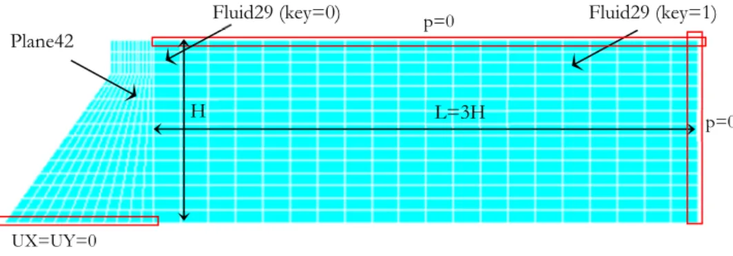
5.2 Finite Element Numerical Model
The finite element model is developed using ANSYS v.14.5. The structure is meshed with plane strain quadrilaterals of type PLANE42, using linear interpolation functions. Fluid domain consists of acoustic medium quadrilaterals of type FLUID29. Finite elements and corresponding degrees of freedom are depicted on Figure 7. Nodes at the dam´s foundation are restrained in both x and y directions. Boundary conditions for the fluid domain pressures are set as null at the top of the res-ervoir and the far field domain. Figure 8 illustrates the general scheme used in the discretization and the prescribed boundary conditions.
Figure 7: Finite elements and corresponding degrees of freedom. Plane42
Fluid29 (key=0): UX,UY, p Fluid29 (key=1): p + pres(p) UX UY UX UY Fluid29
Figure 8: Finite element fluid-structure model and prescribed boundary conditions. 5.3 Seismic Input Records
The Hollister earthquake, which occurred in 1974 and was recorded at the City Hall station is se-lected as the earthquake input function (Figure 9). This event, approximately 15 seconds long, was marked by a peak ground acceleration of approximately 0.12g. This latter information is sufficient for the calculation of seismic loadings and stress distribution produced by the Pseudo-Static Meth-od, which will be later compared to those obtained on a time domain dynamic analysis.
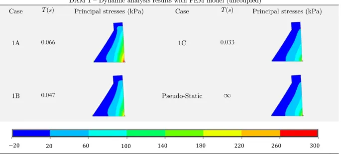
5.4 Dam 1 – Dynamic Analysis Results
Transient dynamic simulations of cases 1A to 1D were performed. Tables 4-5 and Figure 10 depict the maximum principal stress values (selected over the time domain history), as well as the results obtained using the Pseudo-Static Method. Analysis of these results indicates that, in exception of Case 1C, stresses are greatly magnified by dynamic analysis (as shown by the contour values). In Case 1A, for example, tensions in the upstream face are greater than twice the produced by the Pseudo-Static Method, as shown by Figure 10. However, an excellent agreement is achieved be-tween the latter method and Case 1C, which is a very rigid dam. In all cases the intensity of princi-pal stresses is negligible.
Figure 9: Graphs of (a) seismic record and (b) frequency spectrum for the Hollister Earthquake. 0 4 8 12 16 -0.15 -0.1 -0.05 0 0.05 0.1 0.15 t(s) 0 4 8 12 16 20 0 0.01 0.02 0.03 0.04 0.05 f(Hz) L=3H p=0 H Plane42 Fluid29 (key=1) UX=UY=0 Fluid29 (key=0) p=0
DAM 1 – Dynamic analysis results with FEM model (uncoupled)
Case T s( ) Principal stresses (kPa) Case T s( ) Principal stresses (kPa)
1A 0.066 1C 0.033
1B 0.047 Pseudo-Static ¥
Table 4: Maximum principal stresses results for Dam 1 (interaction neglected).
In the scenario of dam-reservoir interaction (coupled analysis) stresses are also amplified, as shown by Table 5. These results follow the same pattern described by the previous table, with dam flexibility acting as a key parameter in assessing earthquake response. At this point it should be noted that the time varying nature of ground input described in Figure 9 is completely irrelevant for the Pseudo-Static Method.
Figure 10: Section cut at elevation 8.75m – Dam 1.
300 260 220 180 140 100 60 20 20 0 4 8 12 0 40 80 120 160 1A 1 1 Pseudo-Static 1
DAM 1 – Dynamic analysis results with FEM model (coupled)
Case T s( ) Principal stresses (kPa) Case T s( ) Principal stresses (kPa)
1D 0.079 Pseudo-Static ¥
Table 5: Maximum principal stresses results for Dam 1 (with reservoir). 5.5 Dam 2 – Dynamic Analysis Results
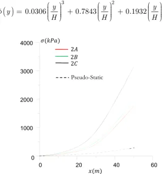
Peak responses of maximum principal stresses are given by Tables 6-7 and Figure 11. Analysis re-sults indicate a strong amplification of ground motion (as shown by contour values). Principal stresses in Case 2A, for example, are almost ten times higher than those obtained with the Pseudo-Static Method. Tension magnitude is also relevant, reaching almost 2MPa. Reservoir effects now play an important role, with upstream tension of almost 3MPa at Case 2C.
5.6 Dam 2 – Proposed Pseudo-Dynamic Roadmap for Case 2C
Previous results indicate that the traditional procedure may underestimate stress field distribution. In contrast, a full dynamic analysis using a fluid-structure model requires an excessive computa-tional cost. A viable alternative arises in application of the Pseudo-Dynamic Method, using equiva-lent static loads indicated in Equations (13) and (16). A roadmap for application of this procedure is presented for Case 2C. The first step consists in finite element evaluation of generalized parame-ters for the uncoupled structure, as shown by Tables 8-9 (obtained with a modal analysis in AN-SYS, fundamental mode). Additionally, an interpolation function is prescribed for horizontal dis-placements at the upstream face, Equation (24).
DAM 2 – Dynamic analysis results with FEM model (uncoupled)
Case T s ( ) Principal stresses (kPa) Case T s( ) Principal stresses (kPa)
2A 0.234 2B 0.185
Pseudo-Static ¥
Table 6: Maximum principal stresses results for Dam 2 (interaction neglected).
460 300 220 140 60 20 380 3200 2540 1890 1230 576 80
DAM 2 – Dynamic analysis results with FEM model (coupled)
Case T s ( ) Principal stresses (kPa) Case T s ( ) Principal stresses (kPa)
2C 0.242 Pseudo-Static ¥
Table 7: Maximum principal stresses results for Dam 2 (with reservoir).
( )
y 0.0306 y 3 0.7843 y 2 0.1932 yH H H
f = çççæ ÷÷÷ +÷ö çççæ ÷÷ +÷ö÷ ççæç ÷÷÷ö÷
è ø è ø è ø (24)
Figure 11: Section cut at elevation 29.58m – Dam 2.
Finite element modal analysis results – fundamental mode
Dam only T s( ) Dam-reservoir T s( )
0.185 0.242
Table 8: Modal analysis results – fundamental mode (Case 2C).
Fundamental mode generalized parameters – structure only
Mass M Ns m( 2 ) Rigidity (K N m ) Earthquake Participation Factor L Ns m( 2 )
1.06e6 1.23e9 2.10e6
Table 9: Uncoupled structure generalized parameters (fundamental mode).
6000 4780 3550 2330 1100 120 0 20 40 60 0 1000 2000 3000 4000 2 2 Pseudo-Static 2
The second step is given by evaluation of the coupled fundamental frequency w with the aid of Equation (11). Thus, the solution of the latter equation results in:
25.67 rad/ ; s T 0.245s
w = = (25a,b)
Substitution of (25a) in (10) and evaluation of (12) provides the coupled structure generalized parameters, shown in Table 10.
Fundamental mode generalized parameters – fluid terms
Generalized fluid added mass Mf(Ns2 m) Additional Earthquake Component N Ns m( 2 )
0.80e6 1.07e6
Table 10: Interaction effects generalized parameters (fundamental mode).
As stated previously, the Pseudo-Dynamic Method consists in evaluation of the maximum dam-reservoir system response. A displacement response spectrum for the earthquake input record shown in Figure 9a is obtained with the aid of Seismosignal software and illustrated in Figure 12.
Analysis of the displacement response spectrum for T =0.245sprovides Sd =0.012m. Addi-tional parameters needed for evaluation of Equation (16) are given by: L Mr , r m ys
( )
and mf( )
y .The last two terms are obtained without difficulty with the dam division into a few horizontal sec-tions. In this example, seven divisions are employed and the equivalent load in each of these posi-tions is indicated in Table 11. Traditional procedure results are also presented (Pseudo-Static). Dif-ferent magnitudes of equivalent static loads in both approaches are easily perceived. Once obtained, the loading indicated in Table 11 is applied to an equivalent static analysis of the dam. Table 12 illustrate these results using the Pseudo-Dynamic loads and makes a comparison with the stress distribution resulting from a full dynamic analysis.
Figure 12: Displacement response spectrum – Hollister Earthquake. 0 0.2 0.4 0.6 0.8 1 0 0.01 0.02 0.03 0.04 0.05 Sd(m) 0.012 0
/
y H Equivalent static load (kN/m)
Pseudo-Dynamic Pseudo-Static 1 674.011 58.907 0.94 760.665 79.359 0.82 789.744 94.288 0.61 913.757 146.668 0.41 841.248 194.372 0.20 714.216 240.616 0 571.476 285.150
Table 11: Equivalent static loads (Case 2C).
Maximum principal stress results – Case 2C
(a) (b)
Table 12: Maximum principal stress results for (a) Pseudo-Dynamic Method
and (b) Transient fluid-structure finite element model. Units in kPa. 6 CONCLUDING REMARKS
In this paper the analysis of seismic actions in concrete gravity dams was investigated by three dif-ferent approaches: (1) Pseudo-Static Method, (2) Pseudo-Dynamic Method and (3) Dynamic analy-sis in the time domain. Two geometries were chosen: dams of small height (Dam 1) and moderate height (Dam 2). The choice was deliberate and intended to demonstrate the relationship between ground input and structural properties in assessing the dynamic response. In fact, Dam 1 showed amplification in the stress distribution per variation on its dynamic properties (in this case, the fundamental period). Only on the scenario of vibration period virtually nil there is an equivalence between the results obtained with the traditional procedure and with the dynamic analysis (Table 3). Proof of this is Case 1C, where T = 0.033s. Similar limit had already been established by Ghrib et al. (1997). For Dam 1, the observed tensions are of small magnitude and explained by the gap between the fundamental frequency and the dominant range of the seismic spectrum (Figure 9b), which stores characteristics of large amplitudes at low frequencies. On the other hand, Dam 2 (which has a lower fundamental frequency) presented considerable tension values, capable of gov-erning the structural design for concrete tension limits. In some cases, the magnitude of stress val-ues obtained from the dynamic analysis were approximately ten times higher than those obtained in the Pseudo-Static Method (Figure 11). However, the authors point to the absence of structural damping, which would lead to smaller amplification values.
As a fluid-structure dynamic analysis requires excessive computational cost, an alternative aris-es with the use of the Pseudo-Dynamic Method. A detailed example, using generalized parameters
6000 4780 3550 2330 1100 120
from a finite element uncoupled model and fluid parameters from proposed expressions (10)-(12) was presented, and results are in agreement with those obtained in a dynamic analysis (Table 12). The major advantage of the proposed solution lies in the fact that any simple finite element code can be applied for solution with this strategy, and complex fluid-structure models are avoided.
The authors hope that the previous results serve as a warning to users of the traditional Seismic Coefficient Method and that they are aware that the hypothesis of a rigid body is unlikely to be met for usual concrete gravity dams (with moderate or tall structures).
Acknowledgments
The authors thank the Brazilian National Research and Development Council - CNPq for the fi-nancial resources (grants) received for this work.
References
ANSYS Multiphysics v.14.5. Ansys Inc.
Chopra, A. K., (2001). “Dynamics of Structures: Theory and Applications to Earthquake Engineering”. 2a ed., Pren-tice Hall, New Jersey.
Chopra, A. K., Chakrabarti, P., (1971). “The Koyna Earthquake of December 11, 1967 and the Performance of Koyna Dam”. UCB/EERC-71/1, Earthquake Engineering Research Center, University of California, Berkeley, 113 p. Chopra, A.K. (1978) – “Earthquake resistant design of concrete gravity dams.” Journal of the Structural Division, ASCE, Vol. 104, pp. 953-971.
Clough, R. W., Penzien, J., (1993) “Dynamics of Structures”. 2ed., McGraw-Hill, Inc., New York.
Committee on Earthquake Engineering - CEE (1990). Earthquake Engineering for Concrete Dams: Design, Perfor-mance, and Research Needs. Washington: National Academy Press.
Fenves, G. F., Chopra, A. K., (1985). “Effects of Reservoir Bottom Absorption and Dam-Water-Foundation Rock Interaction on Frequency Response Functions for Concrete Gravity Dams.” Earthquake Engineering and Structural Dynamics, vol. 13, pp. 13-31.
Fenves, G. L., Chopra, A. K., (1984). “Earthquake Analysis and Response of Concrete Gravity Dams”, UCB/EERC-84/10, Earthquake Engineering Research Center, University of California, Berkeley, 228 p.
FERC - Federal Energy Regulatory Commission, (2002). “Chapter III Gravity Dams”. In: Federal Energy Regulatory Commission, Office of Hydropower Licensing. Engineering guidelines for evaluation of hydropower projects. Wash-ington.
Ghrib, F.; Léger, P.; Tinawi, R.; Lupien, R. Veilleux, M., (1997) - “Seismic safety evaluation of gravity dams”. In: International Journal on Hidropower & Dams, v. 4, n. 2, p. 126-138.
Hong, K. L.; Kim, J., (1995a). “Analysis of Free Vibration of Structural-Acoustic Coupled Systems. Part I: Develop-ment and Verification of the Procedure”. In: Journal of Sound and Vibration, 188(4), p. 561-575.
Hong, K. L.; Kim, J., (1995b). “Analysis of Free Vibration of Structural-Acoustic Coupled Systems. Part II: Two and Three-Dimensional Examples”. In: Journal of Sound and Vibration, 188(4), p. 577-600.
Lecrerc, M.; Léger, P.; Tinawi, R., (2000). “CADAM 2000 user´s manual”. versão 1.0.1. Montreal: École Polytech-nique de Montreal.
Lee, G. C.; Tsai, C. S., (1991). “Time domain analyses of dam reservoir system. I: Exact solution”. In: Journal of Engineering Mechanics, ASCE, vol. 117, no. 9, p. 1990-2006.
Miquel, B., Bouaanani, N., (2010). “Simplified evaluation of the vibration period and seismic response of gravity dam–water systems”. Engineering Structures, Vol. 32, pp. 2488-2502.
Miquel, B., Bouaanani, N., (2014) “Efficient modal dynamic analysis of flexible beam-fluid systems”. Applied mathe-matical modeling, Vol. 39, pp. 99-116.
NBR15421 (2006). Projeto de Estruturas Resistentes a Sismos – Procedimento. Associação Brasileira de Normas Técnicas – ABNT, 2006.
Pretlove, A. J., (1965). “Free vibrations of a rectangular panel backed by a closed rectangular cavity”. In: Journal of Sound and Vibration, vol. 2, p. 197-209.
Priscu, R. (1985). “Earthquake Eigineering for Large Dams.” 2. ed. Bucaresti: Editura Academiei.
Rashed, A., (1983). “Dynamic Analyses of Fluid-Structure Systems”. PhD thesis, California Institute of Technology, Pasadena, California.
Ribeiro, P. M. V., (2006). Uma Metodologia Analítica para a Avaliação do Campo de Tensões em Barragens Gravi-dade de Concreto durante Terremotos. 162p. Master Thesis (Mestrado em Estruturas e Construção civil) – Depar-tamento de engenharia civil e ambiental, Universidade de Brasília, Brasília, 2006.
Ribeiro, P. M. V., (2010). “Soluções Analíticas para Cavidades Acústicas Bidimensionais com Aplicação ao Estudo da Interação Dinâmica Barragem-Reservatório”, PhD thesis. Publicação E.TD-004A/10, Departamento de Engenharia Civil e Ambiental, Universidade de Brasília, Brasília, DF, 306 p.
Ribeiro, P. M. V., Pedroso, L. J., (2010). “Solution of the dynamic interaction problem between a framed structure and an acoustic cavity using imposed deformation functions at the interface”. Mathematical Problems in Engineering, Research Article, Vol. 2010.
SEISMOSIGNAL v.3.3.0. “Seismic analysis software”.Seismosoft, Inc. Available at: http://www.seismosoft.com. Silva, S. F., (2007). “Interação Dinâmica Barragem-Reservatório: Modelos Analíticos e Numéricos”, PhD thesis (Dou-torado em Estruturas e Construção Civil), Publicação E.TD-05A/07, Departamento de Engenharia Civil e Ambien-tal, Universidade de Brasília, Brasília, DF, 220 p.
Tedesco, J. W., McDougall, W. G., Ross, C. A., (1998). “Structural Dynamics: Theory and Applications”. Prentice Hall, 1998.
USBR - United States Bureau of Reclamation (1976). “Design of gravity dams”. Denver: United States Department of the Interior – Bureau of Reclamation.
Westergaard, H.M. (1933) – “Water pressures on dams during earthquakes.” Transactions ASCE, 59(8), Part 3, pp. 418-472.
Xing, J. T.; Price, W. G.; Pomfret, M. J.; Yam, L. H., (1997). “Natural Vibration of a Beam-Water Interaction Sys-tem”. In: Journal of Sound and Vibration, 199(3), p. 491-512.

![Figure 2: Response spectrum generation scheme (adapted from [17]).](https://thumb-eu.123doks.com/thumbv2/123dok_br/19253127.976676/6.808.165.687.89.370/figure-response-spectrum-generation-scheme-adapted.webp)