Brazilian Microwave and Optoelectronics Society-SBMO received 12 Feb 2018; for review 08 Mar 2018; accepted 01 Aug 2018
Abstract—The basic frequency diverse array (FDA) using linearly
increasing frequency increments generates a range-angle dependent beampattern. However, it is coupled in range and angle dimensions and is also periodic in range and time, making its applications limited. In this paper, a novel FDA beampattern synthesis approach is proposed utilizing the time-modulated double parameters based on the chaos sequence. The chirp signal mechanism is used instead of the single-frequency signal mechanism. Meanwhile, the multi-carrier architecture is used for range-angle decoupling. Satisfactory time-invariant range-angle beampattern can be synthesized for both single and multiple targets locations. Simulation results show the effectiveness of the proposed FDA scheme. Furthermore, comparative study with the existing technology indicates that the proposed approach can provide better performance in spatial focusing and side-lobe suppressing.
Index Terms—beampattern synthesis, chaos sequence, frequency diverse array, time modulation.
I. INTRODUCTION
First proposed in [1] and [2], frequency diverse array (FDA) technology generates beampatterns
that depend on the range, angle and time by introducing a tiny frequency offset among the array
elements. In a conventional array, the beampattern can be focused to the desired angle utilizing the
progressive phase shift (PPS) between the elements [3-4], but the beam steering is fixed in an angle
for all range cells. The FDA transmits the beampattern over the desired range and angle thus it can
suppress range-dependent interferences and clutters which is desirable in radar applications. Besides,
the FDA provides new degrees of freedom in the range, angle and time for designing the array factor,
which enables the beam to scan without the need of phase shifters or mechanical steering [5].
Therefore the FDA can offer much capabilities such as synthetic aperture radar imaging [6], auto
scanning [7] and localization of targets [8], etc.
In the basic FDA, the linearly increasing frequency increments are applied and result in a
beampattern coupled in range and angle domains, which has a ‘S’ shape [5]. This characteristic limits
FDA’s applications in unambiguously localizing targets in range-angle dimension [9]. Moreover, the basic FDA beampattern is periodic in range and time, deteriorating the resulting
signal-to-Beampattern Synthesis for Frequency Diverse
Array Based on Time-Modulated Double
Parameters Approach
Tong Mu, Yaoliang Song, Zhonghan Wang
Brazilian Microwave and Optoelectronics Society-SBMO received 12 Feb 2018; for review 08 Mar 2018; accepted 01 Aug 2018
interference-plus-noise ratio (SINR) and target detectability. The range and time periodicity of FDA
beampattern is analyzed in [10], and the range-angle coupled beamforming has been investigated
using frequency-diverse chips in [11]. A logarithmic frequency offset scheme is proposed in [12]
which can decouple the beampattern and eliminate the range periodicity. However, its reduced
range-angle resolution and enhanced side-lobes may not be acceptable for most applications. A FDA system
based on multi-carrier frequencies with logarithmic frequency offset is proposed in [13], which
requires additional convex optimization algorithm for synthesizing the complex element weights to
generate dot-shaped beampatterns. Particularly, the beampatterns generated by these approaches are
time-variant, causing the loss in SINR and seriously affecting the target detectability because of
extremely short duration of the beam illumination at the target position. Time-independent
beampattern based on time-modulated frequency offset (TMFO) is proposed in [14], but the range
periodicity is still not eliminated. Then, time-invariant beampattern with a single maximum at the
target location is achieved in [15] using the time-modulated logarithmically increasing frequency
offset (TMLFO). Also in [15], time-modulated optimized frequency offset (TMOFO) is developed for
obtaining better spatial focusing performance. Recently, multi-carrier architecture combined with
nonlinear distributed frequency offset is proposed in [16] and pencil-shaped time-invariant
beampattern is achieved.
The existing research are based on the single-frequency signal mechanism and thus only single
parameter modulation is considered, namely the frequency offset modulation. In this paper, a novel
FDA beampattern synthesis approach is proposed based on the chirp signal mechanism where
frequency offset as well as chirp constant modulation are both considered. The Logistic mapping
chaos sequence is applied for the double parameter modulation, and the multi-carrier architecture is
employed to decouple the beampattern in range and angle dimensions. Time-invariant beampattern at
the desired location can be achieved by the proposed approach. Also, the time window version of the
proposed FDA is used for multiple targets scenario. Simulation experiments are carried out to
evaluate the performance of the proposed approach. The results are also compared with the
Multi-Carrier-FDA (MC-FDA) recently proposed in [16] and it turned out that the proposed FDA can
provide improved spatial focusing performance with more effective side-lobe suppression
Brazilian Microwave and Optoelectronics Society-SBMO received 12 Feb 2018; for review 08 Mar 2018; accepted 01 Aug 2018
II. TIME-MODULATED DOUBLE-PARAMETER FDA
A. Signal model
Consider an antenna array of M identical transmit elements with uniform spacing d.
Fig. 1. Diagram of the proposed FDA.
As shown in Fig. 1, P is an observation point in the far field, and rm is the distance from P to the
th
m element. Multi-carrier framework is considered in the system thus each transmit element emits a weighted summation of a series of basic signals. Unlike the previous research, the chirp signal instead
of the single-frequency signal is used here as the carrier. Suppose the number of carriers at each
element is N, then the signal transmitted from the thm element is
2 , ,
1
1 2 ( )
2 ,
0
( ) n m n m , 0 , 0 1
N j f t u t
m n m
n
x t a e t T m M
(1)where an m, , fn m, and un m, are the complex weight used for steering the maximum of the beampattern at the target location, radiation frequency and chirp constant for the thn carrier at the thm element, respectively. T is the duration of the transmitted pulse signal. The frequency component fn m, can be expressed as
, 0 , , 0 1, 0 1
n m n m
f f f n N m M (2) where f0 is the reference frequency and fn m, is the frequency offset.
Therefore, the overall signal observed at an arbitrary far field point ( , )P r is
2
, ,
1
1 1 2 [ ( ) ( ) ]
2 ,
0 0
( , , )
m m n m n m
r r
M N j f t u t
c c
n m
m n
X t r a e
(3)where c is the speed of light in free space, r and are the range and azimuth angle from the point to the first element respectively, and rm is the distance between the point and the mth element.
Taking the far field approximation into consideration yields
sin
m
Brazilian Microwave and Optoelectronics Society-SBMO received 12 Feb 2018; for review 08 Mar 2018; accepted 01 Aug 2018 2
0 , ,
, 2 2
0
0 , ,
sin 1 sin
1 1 2 [( )( ) ( ) ]
2 ,
0 0
2( ) sin
sin
sin 1 sin
1 1
2 ( ) 2 { ( ) [( ) ( ) ]}
2 ,
0 0
( , , ) n m n m
n m
n m n m
r md r md
M N j f f t u t
c c n m m n r t md f md f md
r M N r r md c
j f t j f t u t
c c c c c c c
n m
m n
X t r a e
e a e
(5)In practical FDA system, the frequency offset satisfies
, 0
max{fn m} f (6)
thus the term fn m, mdsin
c
can be neglected from (5). Besides, the term
2
2( ) sin
sin ( ) r t md md c c c
in (5) can also be ignored because
, 2 , sin 1 sin ( ) 2 n m n m f md md u c c
(7)
, ,
2( ) sin
1
( )
2 n m n m
r
t md r
c
u f t
c c
(8)
Therefore, (5) can be further approximated as
2 0
0 , ,
sin 1
1 1
2 ( ) 2 [ ( ) ( ) ]
2 ,
0 0
( , , ) n m n m
f md
r M N r r
j f t j f t u t
c c c c
n m
m n
X t r e a e
(9)Then the corresponding array factor (AF) can be obtained
2 0
, ,
sin 1
1 1 2 [ ( ) ( ) ]
2 ,
0 0
( , , ) n m n m
f md r r
M N j f t u t
c c c
n m
m n
AF t r a e
(10)B. Beampattern synthesis based on the proposed FDA
Linear incremental frequency offset makes the FDA beampattern periodic in range and time, while
nonlinear distributed time-modulated frequency offset can result in time-invariant spatial focusing
beampattern. In order to eliminate the time-variant and range-periodic characteristics of the
beampattern, and also improve the performance of the FDA system in spatial focusing and side-lobe
suppressing, a new scheme based on the time-dependent frequency offset and chirp constant is
designed, namely the Time-Modulated Double-Parameter FDA (TMDP-FDA). Suppose the target
position is ( ,r0 0), and for the thn carrier at the thm element, the frequency offset and chirp constant are defined as
, ,
0
= n m
Brazilian Microwave and Optoelectronics Society-SBMO received 12 Feb 2018; for review 08 Mar 2018; accepted 01 Aug 2018
respectively with t[0, ]T and T r0
c
. f and u are the frequency offset and chirp constant
controlling coefficients respectively. For each element, pn m, and qn m, are generated by the chaos sequence based on the Logistic mapping and they are given by
0, ,
1, 1,
, 0
4 (1 ), 1 1
m n m
n m n m
p n p
p p n N
(13)
0, ,
1, 1,
, 0
4 (1 ), 1 1
m n m
n m n m
q n q
q q n N
(14)
where p0,m and q0,m are the initial values for the thm element and satisfy 0<p0,m<1 and 0<q0,m<1, respectively. The transmit beampattern can be decoupled as range and angle parts by applying the
multi-carrier architecture [16], therefore the resulting array factor can be expressed as
, , 2
2
0 0 0
2 1
2 [ ( ) ( ) ]
sin 2
1 1 2 ( )
0 0
( , , )
n m n m
p r q r
j f t u t
f md r c r c
M N j t t
c c c
r
m n
AF t r a e a e
(15)with an m, =a a r. Obviously, the beampattern value of (15) is maximum for t0,r0, 0. To steer the maximum at the desired target position ( ,r0 0), the corresponding complex weights are designed as
0 sin 0
2 f md
j c
a e
(16)
, ,
2 ( n m n m)
j fp uq
r
a e (17) respectively. Without loss of generality, the time variable is set as t0, and by substituting (16) and (17) into (15) the array factor can be further deduced as
2 2
, 0 , 0
0 0
2
0 0
( ) ( )
(sin sin )
1 1 2 2 [ ]
0 0
( , )
n m n m
p r r q r r
f md
M N j j f u
r r
c
m n
AF r e e
(18)Therefore, the beampattern maximum is generated at the desired location based on the designed
complex weights.
C. Beampattern synthesis for multiple targets
For multiple targets scenario, the time window version of the proposed FDA can be used to
generate multiple maximums at the positions of different targets. Suppose there are I targets in the space located at ( , )ri i respectively, i1,2,...,I. Then the duration of single transmit pulse can be
Brazilian Microwave and Optoelectronics Society-SBMO received 12 Feb 2018; for review 08 Mar 2018; accepted 01 Aug 2018 Fig. 2. Division of single pulse duration.
During the thi time window, the frequency offset and chirp constant for the thn carrier at the thm
element are defined as
, , 0 = ( ) n m i n m p f f r t t c (19) , , 2 0 2 = ( ) ( ) n m i n m q u u r t t c (20)
respectively where r t0( ) is given by
0( ) [ ( i 1) ( i)] ,i [i1, )i
r t tt tt r t t t (21) and 1, 0 ( ) 0, 0 t t t
< (22)
As a result, by combining the time window subdivision with the chirp signal mechanism, the solution
for multi-targets beampattern synthesis is given by
, , 2
2
0 0 0
2 1
2 [ ( ) ( ) ]
sin ( ) 2 ( )
1 1 2 ( )
1
0 0
( , , ) , [ , )
n m n m
p r q r
j f t u t
f md r t c r t c
M N j t t
i i c i c c
r i i
m n
AF t r a e a e t t t
(23)Similar with (16) and (17), the complex weights for steering the maximum at the thi desired target position ( , )ri i are designed as
0 sin
2 f md i
j
i c
a e
(24)
, ,
2 ( n m n m)
j fp uq
i r
a e (25) respectively. It can be seen that the angle complex weight needs to be changed for different subpulses,
while the range complex weight remains unchanged during the total pulse duration.
III. NUMERICAL SIMULATIONS
A. Simulation setup
In this section, simulation experiments are carried out to examine the effectiveness of the proposed
TMDP-FDA. The numerical data are obtained by MATLAB R2013b on the PC with CPU frequency
being 3.3GHz and RAM being 8GHz, and the processing time for the beampattern synthesis code of
Brazilian Microwave and Optoelectronics Society-SBMO received 12 Feb 2018; for review 08 Mar 2018; accepted 01 Aug 2018
15
M , carrier number is N10, pulse duration is T 1ms and reference frequency is f05 GHz. In order to avoid the grating lobes in angle dimension, the interelement spacing is set as
, 2 max{ n m}
c d
f
. The scope of range and angle domains are set as 0 r 1000km and
-90 90 respectively, and the target location is (500km, 30 ) . The frequency offset and chirp
constant controlling coefficients are set as f 7 and u 5 respectively. Two pseudo random sequences each containing M values between 0 and 1 are generated and stored to serve as the initial values of pn m, and qn m, .
(a) (b) (c)
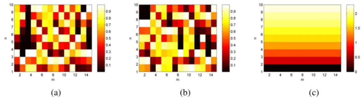
Fig. 3. Matrix of (a) pn m, , (b) qn m, and (c) logarithmic function.
The matrix P made up of pn m, and Q made up of qn m, are depicted in Fig. 3 (a) and (b) respectively. The logarithmic function used in MC-FDA for controlling the frequency offset is also
shown in Fig. 3 (c) for comparison. It can be seen that for P and Q, the sequence with respect to
each element is nonlinear, non-monotonic, irregular and different from each other. As for Fig. 3 (c),
the sequence with respect to each element is nonlinear, monotonic increasing and the same with each
other.
B. Results and discussions
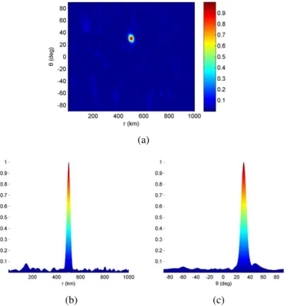
If the time is fixed, the beampattern in a 3-D plot in range and angle domains can be illustrated
which contains the spatial information of the beampattern. Fig. 4 shows the normalized beampattern
of the proposed TMDP-FDA when t 0. From Fig. 4 (a) it can be seen that a single maximum of the beampattern appears right at the desired target location. The range periodicity is eliminated and good
range-angle decoupling is realized, indicating the satisfactory spatial focusing performance of the
proposed approach. For analyzing the side-lobe level (SLL), the generated beampattern is projected
into range and angle dimensions, as shown in Fig. 4 (b) and (c), respectively. It shows that the peak
SLL in both range and angle dimensions are below 0.1, indicating the effective side-lobe suppressing
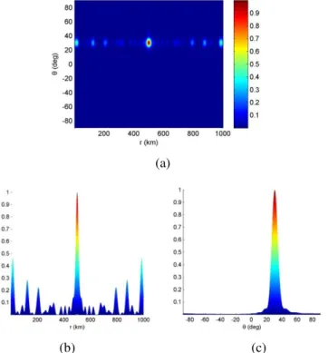
performance of the proposed method. The results at t 0 obtained by the MC-FDA are depicted in Fig. 5. It shows that the MC-FDA can also produce fine spatial focusing beampattern with low SLL.
However, the main-lobe beam width in range dimension of the TMDP-FDA is narrower, which means
more energy can be transmitted at the target location and target detecting with higher accuracy can be
Brazilian Microwave and Optoelectronics Society-SBMO received 12 Feb 2018; for review 08 Mar 2018; accepted 01 Aug 2018
(a)
(b) (c)
Fig. 4. Normalized beampattern of the TMDP-FDA in (a) range-angle dimension, (b) range dimension and (c) angle dimension at t 0.
(a)
(b) (c)
Fig. 5. Normalized beampattern of the MC-FDA in (a) range-angle dimension, (b) range dimension and (c) angle dimension at t 0.
Brazilian Microwave and Optoelectronics Society-SBMO received 12 Feb 2018; for review 08 Mar 2018; accepted 01 Aug 2018
6 and Fig. 7, respectively. It is observed that the main-lobe beam width in range dimension of the two
methods both get narrower, and meanwhile, the peak SLL of the TMDP-FDA is still below 0.1. As for
the MC-FDA, several high side-lobes appears in the range dimension and the peak SLL is 0.465.
(a)
(b) (c)
Fig. 6. Normalized beampattern of the TMDP-FDA in (a) range-angle dimension, (b) range dimension and (c) angle dimension at t1ms.
(a)
(b) (c)
Brazilian Microwave and Optoelectronics Society-SBMO received 12 Feb 2018; for review 08 Mar 2018; accepted 01 Aug 2018
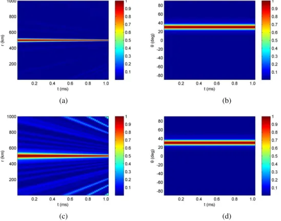
In order to verify the time-invariant characteristic of the TMDP-FDA, the beampattern is projected
into time-range and time-angle dimensions, as shown in Fig. 8 (a) and (b), respectively. It is observed
that the location of the beampattern maximum in both range and angle dimensions remains unchanged
as the time increases in a pulse duration. Correspondingly, Fig. 8 (c) and (d) show the results of the
MC-FDA. From Fig. 8 (c) it can be seen that the number and the level of side-lobes in range
dimension increase as the time changes, which is not observed in the TMDP-FDA. In addition, the
main-lobe beam width in angle dimension of the two methods are the same and do not change with
time. It is because the beampattern is totally decoupled as range and angle by applying the
multi-carrier, and the time modulation acts only on the range dimension. For acquiring narrower beam width
in angle dimension, one can increase the number of transmit elements to enlarge the array aperture.
(a) (b)
(c) (d)
Fig. 8. Beampattern projection on (a) time-range dimension for TMDP-FDA, (b) time-angle dimension for TMDP-FDA, (c) time-range dimension for MC-FDA and (d) time-angle dimension for MC-FDA.
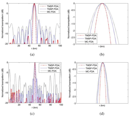
Comparisons of the main-lobe width in range dimension for three different schemes are provided in
Fig. 9, i.e. the TMDP-FDA, the Time-Modulated Single-Parameter FDA (TMSP-FDA) and the
MC-FDA. Fig. 9 (a) and (b) show the result at t0 and its amplified detail, and Fig. 9 (c) and (d) show the result at t1ms and its amplified detail. Notice that the only difference between the TMDP-FDA and TMSP-FDA defined here is that the latter uses the single-frequency signal mechanism thus it
contains only frequency offset modulation. The results show that the use of chirp signal combined
Brazilian Microwave and Optoelectronics Society-SBMO received 12 Feb 2018; for review 08 Mar 2018; accepted 01 Aug 2018
signal combined with chaos sequence modulation, both of which are superior to the logarithmic
function based single parameter modulation.
(a) (b)
(c) (d)
Fig. 9. Beam width comparisons in range dimension at (a) t0, (b) amplified detail of (a), (c) t1ms and (d) amplified detail of (c).
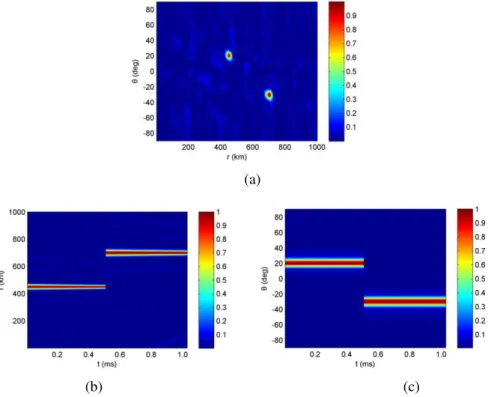
The time window version of the proposed TMDP-FDA is used for multiple targets beampattern
synthesis. For simplicity, it is supposed that there are two targets located at (450km, 20 ) and
(700km, -30 ) respectively. The pulse duration is divided into two time windows, the length of each
is 0.5ms . By fixing the time t0 and t0.5ms respectively, the resulting normalized beampattern for the two targets is shown in Fig. 10 (a). The beampattern projection on time-range and time-angle
dimensions are depicted in Fig. 10 (b) and (c) respectively. It is shown that time-invariant multiple
Brazilian Microwave and Optoelectronics Society-SBMO received 12 Feb 2018; for review 08 Mar 2018; accepted 01 Aug 2018
(a)
(b) (c)
Fig. 10. (a) Normalized range-angle beampattern for two targets, (b) projection on time-range dimension and (c) projection on time-angle dimension.
Furthermore, the effect of changing the value of frequency offset and chirp constant controlling
coefficients to the performance of the TMDP-FDA is investigated. Firstly, the frequency offset is kept
as f 7 and u changes from 1 to 10 and the values of the -3dB main-lobe width in range dimension and the peak SLL for each u are obtained. Then, the chirp constant controlling coefficient is kept as u 5 and f changes from 1 to 10 and the corresponding values for each f
are obtained. The results are depicted in Fig. 11. On the one hand, when one of the controlling
coefficients is fixed and the other one increases, the -3dB main-lobe width in range dimension
decreases, which means narrower beampattern can be obtained. On the other hand, the peak SLL
maintains its small value around 0.1 when the coefficient changes. Therefore, based on the
TMDP-FDA, one can flexibly control the beampattern focusing scope as needed by choosing the appropriate
frequency offset and chirp constant controlling coefficients.
(a) (b)
Brazilian Microwave and Optoelectronics Society-SBMO received 12 Feb 2018; for review 08 Mar 2018; accepted 01 Aug 2018
At last, the initial values p0,m and q0,m are changed by using different pairs of pseudo random sequences, and it turned out that the resulting beampattern is steady in both spatial focusing and SLL.
It indicates that the TMDP-FDA is robust to the initial values thus initial value optimization is not
necessary, which reduces the system design complexity.
IV. CONCLUSION
In this paper, a novel TMDP-FDA beampattern synthesis approach has been proposed.
Time-invariant range-angle beampattern is achieved by using the time-modulated double parameters based
on the chirp signal mechanism. It is able to generate fine spatial focusing beampattern at the desired
location for both single and multiple targets, and it also provides good performance in side-lobe
suppressing. Numerical simulations are carried out to evaluate the performance of the proposed
TMDP-FDA, and the main results are compared with the MC-FDA. It turned out that at a fixed time
the TMDP-FDA has narrower main-lobe beam width in range dimension, and also, it has
satisfactorily lower side-lobes with the time changing in a pulse duration. In addition, the beampattern
focusing scope of the TMDP-FDA can be flexibly controlled by adjusting the corresponding
coefficients and it also reduces the system design complexity.
In future research, the optimal FDA geometric configuration such as the application of planar or
distributed geometry and the receive beamforming for the FDA radar need to be investigated.
Furthermore, for the practical implementation of the proposed FDA scheme, many issues need to be
considered such as generating the waveform, eliminating the intermodulation products of the
frequency mixers and reducing the structure complexity, etc [10,17-18].
ACKNOWLEDGMENT
This work was supported by the National Natural Science Foundation of China under Grant
61271331 and Grant 61571229.
REFERENCES
[1] P. Antonik, M. C. Wicks, H. D. Griffiths and C. J. Baker, “Frequency diverse array radars,” in IEEE Radar Conf., Verona, NY, USA, 2006, pp. 215-217.
[2] M. C. Wicks and P. Antonik, “Frequency diverse array with independent modulation of frequency, amplitude, and phase,” U.S. Patent 7 319 427, Jan. 15, 2008.
[3] C. A. Balanis, Antenna theory: analysis and design, 3rd ed. New York, NY, USA: John wiley & sons, 2005. [4] Y. Konishi, “Phased array antennas,” IEICE T. Commun., vol. E86B, no. 3, pp. 954-967, Mar. 2003.
[5] W. Q. Wang, “Frequency diverse array antenna: new opportunities,” IEEE Antennas Propag. Mag., vol. 57, no. 2, pp. 145-152, Apr. 2015.
[6] J. Farooq, M. A. Temple and M. A. Saville, “Application of frequency diverse arrays to synthetic aperture radar imaging,” in ICEAA, Torino, Italy, 2007, pp. 447-449.
[7] J. J. Huang, K. F. Tong and C. J. Baker, “Frequency diverse array with beam scanning feature,” in IEEE Ap-S, San Diego, CA, USA, 2008, pp. 1982-1985.
[8] W. Q. Wang and H. Z. Shao, “Range-angle localization of targets by a double-pulse frequency diverse array radar,” IEEE J. Sel. Topics Signal Process., vol. 8, no. 1, pp. 106-114, Feb. 2014.
[9] Y. B. Wang, W. Q. Wang and H. Z. Shao, “Frequency diverse array radar Cramér-Rao lower bounds for estimating direction, range, and velocity,” Int. J. Antenn. Propag., vol. 2014, no. 12, pp. 1-15, 2014.
Brazilian Microwave and Optoelectronics Society-SBMO received 12 Feb 2018; for review 08 Mar 2018; accepted 01 Aug 2018 [11]T. Higgins and S. D. Blunt, “Analysis of range-angle coupled beamforming with frequency-diverse chirps,” in WDD,
Kissimmee, FL, USA, 2009, pp. 140-144.
[12]W. Khan, I. M. Qureshi and S. Saeed, “Frequency diverse array radar with logarithmically increasing frequency offset,” IEEE Antennas Wireless Propag. Lett., vol. 14, pp. 499-502, 2015.
[13]H. Z. Shao, J. Dai, J. Xiong, H. Chen and W. Q. Wang, “Dot-shaped range-angle beampattern synthesis for frequency diverse array,” IEEE Antennas Wireless Propag. Lett., vol. 15, pp. 1703-1706, 2016.
[14]W. Khan and I. M. Qureshi, “Frequency diverse array radar with time-dependent frequency offset,” IEEE Antennas Wireless Propag. Lett., vol. 13, pp. 758-761, 2014.
[15]A. M. Yao, W. Wu and D. G. Fang, “Frequency diverse array antenna using time-modulated optimized frequency offset to obtain time-invariant spatial fine focusing beampattern,” IEEE Trans. Antennas Propag., vol. 64, no. 10, pp. 4434-4446, Oct. 2016.
[16]Y. X. Wang, W. Li, G. C. Huang and J. L. Li, “Time-invariant range-angle-dependent beampattern synthesis for FDA radar targets tracking,” IEEE Antennas Wireless Propag. Lett., vol. 16, pp. 2375-2379, 2017.
[17]C. Maffrand, D. Zarate, M. A. Zon, H. Fernandez and M. R. Romero, “Arbitrary waveform generator using FPGA for applications in ultrafast scan voltammetry,” in Proc. IEEE IX Southern Conf. Program. Logic, Buenos Aires, Argentina, 2014, pp. 1-6.