Experimental Study of Transmission and Reflection
Characteristics of a Gradient Array
of Metamaterial Split-Ring Resonators
1
Pedro J. Castro, 2Joaquim J. Barroso, 1Joaquim P. Leite Neto, 2A. Tomaz, and 3Ugur C. Hasar
1
National Institute for Space Research (INPE), 12227-010 São José dos Campos, SP, Brazil
2
Technological Institute of Aeronautics (ITA), 12228-900 São José dos Campos, SP, Brazil
3
Gaziantep University, Gaziantep, 27310 Turkey
AbstractA study of a non-uniform metamaterial array consisting of six split-ring resonators of varying diameters is conducted experimentally to measure the transmission and reflection characteristics that arise from asymmetry in the longitudinal direction. Such characteristics are examined and compared with their counterpart symmetric scattering coefficients associated with a uniform split-ring array. In the non-uniform array the ring diameters vary in steps of 0.5 mm, which yields a gradient geometry. Inserting the non-uniform array in an X-band waveguide operating below cutoff provides a transmission band wider than that obtained from the uniform array. Different from the uniform array, for which the magnetic resonance frequency is on the left and away from the electric resonance frequency, in the gradient array the magnetic response lies inside the electric band.
Index Terms Metamaterials, Split-ring resonators, Gradient array, Electric
and magnetic responses.
I.
INTRODUCTIONMetamaterials are artificially structured metallo-dielectric composites especially engineered to
interact with electromagnetic waves so as to control their propagation characteristics. Generally
incorporating concentric circular split-ring resonators (SRR), such materials can exhibit electric
permittivity and magnetic permeability simultaneously negative. According to the peculiar properties
of the metallic inclusions in the metamaterial unit cell, a periodic structure formed by concentric
rings can be used to allow for wave propagation inside miniaturized waveguide operating below
cutoff [1]-[2]. There are several papers in the literature describing the various aspects of the SRR
structures and metamaterial research [3]-[24], where electromagnetic resonance properties have been
studied both theoretically and experimentally.
Extending our previous work [21], the present paper describes experiments that examine the wave
diameters (gradient), showing its transmission and reflection spectra and how this structure compares
to a uniform array of six 9-mm-diameter rings. In addition to a discussion of the phases of the
S-parameters, measured transmission bands are compared for the uniform and gradient arrays and with
those obtained from full-wave electromagnetic simulation.
II.
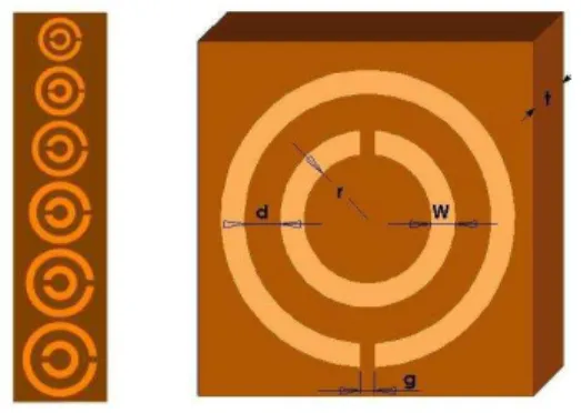
DESIGN AND CONSTRUCTION OF THE NONUNIFORM SPLIT-RING RESONATORThe array under investigation is not a periodic structure, as illustrated on the left of Fig. 1. It
consists of six pairs of concentric rings of varying diameters. The rings are made of copper (thickness
= 37 m) printed on a kapton substrate of relative dielectric constant ε = 3.2 and thickness t = 1.6 mm. The other geometric parameters are: the spacing between the inner and outer ring d = 0.75 mm, ring
width w = 0.80 mm, and the ring gap g = 1.00 mm. The inner ring radius r varies from 1.00 to 2.25
mm with steps of 0.25 mm, such that the smallest and the largest diameter are respectively 6.70 and
9.20 mm. The SRR dimensions were determined from design formulas [1] so that the resonant
wavelength at 4.40 GHz (68.20 mm) is much larger than the diameter of the largest ring (9.20 mm).
The rings act as a distributed capacitance C0 in the equivalent circuit shown in Fig. 2, where L is the
mutual inductance of the ring and Cg the capacitance of the slit (gap) between the rings.
Fig. 1. Schematics of the split-ring resonator (design parameters: d = 0.75 mm, w = 0.80 mm, t = 1.6 mm, r variable from 1.00 to 2.25 mm, g = 1.00 mm, and = 3.2).
Fig. 2. Two-port equivalent network of the SRR unit and its respective transmittance spectrum.
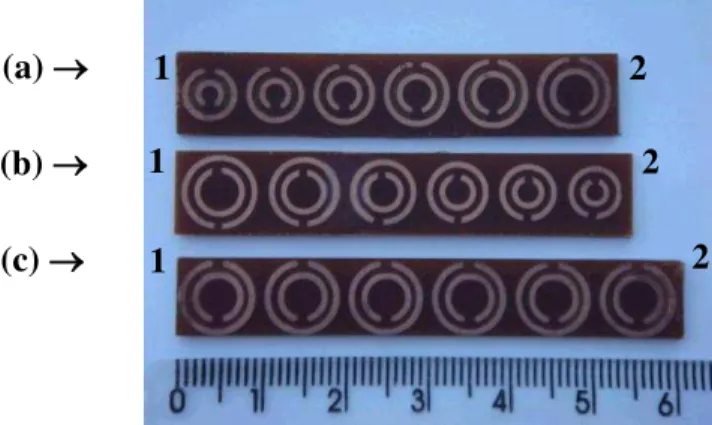
To better guide the objectives of our study, the gradient array with six different split rings of varying
diameters can be separated in two configurations: (a) increasing diameter-ring array, (b) decreasing
diameter-ring array, to be used for the purpose of experimental comparison with (c) constant-diameter
array, as depicted in Fig. 3. Each sample is placed inside a waveguide so as to obtain the
corresponding forward and backward transmission scattering parameters S12 and S21 and the forward
and backward reflection scattering parameters S11 and S22, which are measured at the waveguide ports
1 (input) and 2 (output) of the waveguide.
Inserted in the waveguide, the split-ring array can produce negative permittivity when the operation
negative magnetic permeability is obtained from the interaction between the transverse magnetic field
component and the SRRs, yielding a magnetic response from these resonators thus providing a
passband, often called left-handed transmission band.
Fig. 3. Different configurations for six pairs of SRRs under comparison: (a) increasing diameter-ring array (b) decreasing diameter-ring array, and (c) constant-diameter array (uniform array). Numbers 1 and 2 refer to input and output waveguide ports, respectively.
III.
EXPERIMENTAL ARRANGEMENT AND EXPERIMENTSExperiments were implemented by loading a rectangular X-band waveguide with an array of
split-ring resonators (Fig. 4) to investigate the effect on transmission and reflection bands.
The array is placed on the symmetry plane of a standard WR90 waveguide of 22.86 x 10.16
mm
2cross sectional area and cutoff frequency of 6.55 GHz. The experimental setup is
displayed in Fig. 5, where the waveguide with split-ring array is symmetrically connected on
both ends to identical X-band waveguide-to-coaxial adapters, which are used to excite and
detect the signal propagating through the combined waveguide-SRRs medium.
In order to facilitate the excitation of the SRR array, the first and the last unit cells in the
array were partially placed out of the host rectangular waveguide. An Agilent N5230C vector
network analyzer is used to measure the S
12and S
21transmission and also S
11and S
22reflection coefficients through the loaded waveguide, as well as to collect all the experimental
data. Moreover, the magnitudes of reflection and transmission scattering parameters of the
empty waveguide are measured so that the unloaded waveguide response is obtained,
allowing us to compare the scattering parameters of different arrays.
A commercial 3D electromagnetic simulator
–
CST microwave studio [25] was used to
simulate S-parameters of metamaterial cells. We used the following mesh parameters in our
s
imulations: a) mesh type: hexagonal, b) cell per wavelength =10, and c) cells per maximum modelbox edge = 10 (a total of maximum 11,500 cells).
(a)
1
1
1
(b)
(c)
2
2
IV.
EXPERIMENTAL RESULTSIn Fig. 6 the magnitudes of (a) transmission and (b) reflection scattering parameters of the empty
waveguide are seen where no resonances are observed below the cutoff frequency. This allows us to
compare the measured data of different metamaterial arrays investigated here, as follows below.
Figs. 7 (a) and 7 (b) exhibit the experimental magnitudes with their respective unwrapped phases of
the S12 and S21 transmission coefficients and the S11 and S22 reflection coefficients for the array with
six rings of increasing diameter. We note that six is an adequate number of rings to show the
distinctive features of the S-parameter spectra. For a smaller number of rings, the valley in the 4-9
GHz region [Fig. 7(a)] would be shallower, as demonstrated in [21]-[22]. As shown in the left panel,
there is a coincidence between the transmission coefficients for magnitude and phase, i. e., both the
phases and magnitudes of S12 and S21 are identical. This is because any linear passive network is
electrically reciprocal, namely, S12 = S21. Nevertheless, the phases and magnitudes of S12 and S21 are
not identical over the 1-4 GHz frequency band because below –75 dB, the measured magnitudes are
comparable with the noise level of the VNA instrument, and therefore the measurement accuracy is
considerably low. Concerning the reflection parameters, it is seen in the right panel that S11 is not
equal to S22. Such a feature is due to the asymmetry with respect to the direction of wave propagation
since an asymmetric network is characterized by different forward and backward reflection
coefficients. We note that non-identical reflection scattering parameters and also different forward
and backward wave impedances are exhibited by bi-anisotropic metamaterial slabs [24].
1
1
Fig. 4. X-band waveguide loaded with an array of split-ring resonators.
Fig. 6. Experimental measurements for the empty waveguide showing the magnitudes (dB) of (a) reflection coefficients S11 and S22 and (b) transmission coefficients S12 and S21.
Fig. 7. (a) Experimental measurements for the array of increasing-diameter rings: magnitudes (dB) of transmission coefficients S12 and S21 and their respective phases; (b) magnitudes (dB) of transmission coefficient S11 and S22 and their respective phases ((a’) and (b’)).
The magnitudes of the coefficients S11 and S22 show a visible variation between 6.00 and 12.40 GHz,
even below the cutoff frequency (at 6.55 GHz). This implies very different wave impedances for the
structure depending on which side the incoming wave impinges on the slab. About the phase values,
the variation is clear in the 7.50-10.50 GHz range as shown in the inset of Fig. 7(b’).
(b’)
In Figs. 8 (a) and 8 (b), the same scenario is observed: for the array of decreasing diameter the
relationship S12 = S21 still holds while S11 S22. Moreover, the S11 from increasing gradient
configuration is similar to the S22 from the decreasing gradient one, and vice-versa, as was expected.
Fig. 8. (a) Experimental measurements for the array of decreasing-diameter rings: magnitudes (dB) of transmission coefficients S12 and S21 and their respective phases; (b) magnitudes (dB) of transmission coefficient S11 and S22 and their respective phases ((a’) and (b’)).
Finally, the four scattering parameters for the constant-diameter ring array (uniform array) are
presented in Fig. 9, where the transmission and reflection parameters are practically similar, not
taking into account the occurrences above the X-band and in the floor noise range (< 3.0 GHz and
below -75 dB). In this case, the structure is symmetric in the forward and backward propagation
directions.
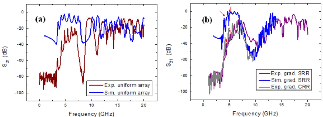
Analyzing the transmission spectrum of the uniform and gradient arrays as illustrated in Figs. 10 (a)
and (b), respectively, the first one has a first passband centered around 3.22 GHz, which corresponds
to the magnetic response, a value well below the 6.55 GHz cutoff frequency, thus featuring a
negative-refractive-index material [1,2]. The second band with six peaks corresponds to the electrical
response, covering the range from 4.03 GHz to 7.90 GHz, by noting that the number of peaks
Fig. 9. (a) Experimental measurements for the array of constant-diameter rings: magnitudes (dB) of transmission coefficients S12 and S21 and their respective phases; (b) magnitudes (dB) of transmission coefficient S11 and S22 and their respective phases ((a’) and (b’)).
In the simulation plot the magnetic transmission peak at 3.50 GHz is almost coincident as well as the
deep around 8.50 GHz, in relation to experimental results, while the electric band is somewhat wider.
In contrast to the uniform array, the gradient structure distinguishes itself by the presence of a wider
transmission band [20] below the cutoff frequency of the empty waveguide, a band that extends from
3.80 to 8.90 GHz, certainly because of the magnetic responses (peaks around 4.50 and 5.20 GHz)
occurring within the electrical band [21]. Indeed, comparing the curves for open (SRR), purple curve,
and closed rings (CRR), grey curve, depicted in Fig.10 (b), we can notice the presence of these two
peaks around 4.50 and 5.20 GHz, pointed out with red arrows; by exclusion, these ones are likely
related to the magnetic responses. Isolated peaks (in red) emerge from the electric-resonance band
caused by the electric response of the gradient array. This is in contrast to what occurs for a uniform
periodic structure containing 9-mm-diameter rings, where the magnetic response is always to the left
of the electric band as shown in Fig. 10 (a). The simulated graph (blue curve) confirms the peaks (red
arrows) at 4.50 and 5.20 GHz which must correspond to the magnetic response. Furthermore, the
transmission bands of gradient and uniform structures are compared with the respective simulation
models by using the CST Microwave Studio with relative consistency, occurring a small offset to the
left on the simulated arrays in both cases, as shown in Fig. 10 (a and b). Dissimilarities between
Brazilian Microwave and Optoelectronics Society-SBMO received 19 May 2016; for review 24 May 2016; accepted 08 Sept 2016 Brazilian Society of Electromagnetism-SBMag © 2016 SBMO/SBMag ISSN 2179-1074 experimental arrangement. In addition to considering straight edge gaps, an oversized driven cavity
instead of a coaxial probe was used to excite the waveguide.
Fig. 10. (a) Measured and simulated S21 magnitudes for the uniform array; (b) measured and simulated values for the gradient array.
V.
CONCLUSIONA study of non-uniform (gradient) and uniform arrays formed by six split rings was performed
experimentally, in which transmission and reflection characteristics were measured. For the uniform
array, the transmission and reflection parameters have the same behavior (S12 = S21) and (S11 = S22),
thus meaning that the array is mirror symmetric and reciprocal. For the gradient arrays with increasing
and decreasing ring diameters, the transmission coefficients are identical (S12 = S21), as the structure is
still reciprocal. On the other hand, the forward and backward reflection coefficients greatly differ in
magnitude and phase due to the asymmetry of the array. In all events the phases proved and
highlighted the behavior of each S parameter. One of the peculiarities of the nonuniform array is that
the magnetic response lies inside the electric band, unlike the uniform network whose magnetic
response is on the left and away from the electric band. This fact contributes to an electromagnetic
band wider than that for the uniform network. Whether the frequency peaks in the frequency spectrum
of the nonuniform array features a negative-refractive index is a point to be investigated further. The
structures studied here allow for the miniaturization of devices since the largest diameter of the ring is
much smaller than the guide wavelength, and in particular the gradient arrays allow broadband
electromagnetic transmission, mainly performing as a band-pass filter.
ACKNOWLEDGEMENT
This work has been supported by FAPESP (São Paulo Research Foundation) and CNPq (National
REFERENCES
[1] J. J. Barroso, P. J. Castro, J. P. Leite Neto. “Experiments on wave propagation at 6.0 GHz in a left-handed waveguide”, Microw. Opt. Techn. Lett., vol. 52, no. 10, pp. 2175-2178, 2010.
[2] R. Marqués, J. Martel, F. Mesa, and F. Medina, “Left-handed-media simulation andtransmission of EM waves in subwavelength split-ring-resonator-loaded metallic waveguides", Phys. Rev. Lett., vol. 89, no. 18, pp. 183901, 2002.
[3] H. O. Moser, B. D. F. Case, O. Wilhelmi, and B. T. Saw, “Terahertz response of a
microfabricated rod-split-ring-resonator electromagnetic material”, Phys. Rev. Lett., vol. 94, pp. (063901)1-4, Feb. 2005.
[4] J. B. Pendry, A. J. Holden, D. J. Robbins, and W. J. Stewart, “Magnetism from conductors and
enhanced nonlinear phenomena”, IEEE Trans. Microw. Theory Tech., vol. 47, pp. 2075-2084, Nov. 1999.
[5] Special Issue on Metamaterials of IEEE Trans. Antennas Propag., vol. 51, no. 10, 2003.
[6] J. Pendry, “Manipulating the near field with metamaterials", Opt. Photonic News, vol. 9, pp.
32-37, 2004.
[7] D. Smith, J. Pendry, and M. Wiltshire, “Metamaterials and negative refraction index", Science,
vol. 305, pp. 788-792, 2004.
[8] S.A. Ramakrishna, “Physics of negative refractive index materials", Rep. Prog. Phys., vol. 68, pp.
449-521, 2005.
[9] E. Ozbay, K. Guven, and K. Aydin, “Metamaterials with negative permeability and negative
refractive index: experiments and simulations”, J. Opt. A: Pure Appl. Opt., vol. 9, pp. S301-S307,
2007.
[10] D. R. Smith, W. J. Padilla, D. C. Vier, S. C. Nemat-Nasser, and S. Schultz, “Composite medium
with simultaneously negative permeability and permittivity”, Phys. Rev. Lett., vol. 84, no. 18, pp.
4184-4187, 2000.
[11] J. Du, S. Liu, Z. Lin, and S. T. Chui, “Magnetic resonance of slotted circular cylinder resonators”,
J. Appl. Phys., vol. 104, pp. (014907)1-7, 2008.
[12] R. Marqués, F. Martín, and M. Sorolla, Metamaterials with Negative Parameters. Hoboken , NJ: Wiley-Interscience, 2008, p. 54.
[13] K. Aydin, E. Ozbay, “Identifying magnetic response of split-ring resonators at microwave
frequencies”, Opto-Electron. Rev., vol. 14, no. 3, p. 193-199, 2006.
[14] K. Aydin, I. Bulu, K. Guven, M. Fafesaki, C. M. Soukoulis, E. Ozbay, “Investigation of magnetic
resonances for different split-ring resonators parameters and designs”, New J. Phys., vol. 7, no. 168, pp. 1-15, 2005.
[15] N. Katsarakis, T. Koschny, M. Koschny, M. Kafesaki, E. N. Economou, C. M. Soukoulis,
“Electric coupling to the magnetic resonance of split ring resonators”, Appl. Phys. Lett., vol. 84,
no. 15, pp. 2943-2945, Ap. 2004.
[16] K. Aydin, E. Ozbay, “Experimental and numerical analyses of the resonances of split ring
resonator”, Phys. Status Solidi (b), vol. 244, no. 4, p. 1197-1201, 2007.
[17] K. Aydin, K. Guven, M. Kafesaki, L. Zhang, C. Soukoulis, E. Ozbay. “Experimental observation
of true left-handed transmission peaks in metamaterials”, Opt. Lett., vol. 29, no. 22, pp. 2623-2625, 2004.
[18] T. Koschny, M. Kafesaki, E. N. Economou, C. M. Soukoulis, “Effective medium theory of left
[19] P. J. Castro, J.J. Barroso, J.P. Leite Neto. “Experimental study on split-ring resonators with
different slit widths”. J. Electromagn. An. Appl., vol. 5, pp. 306-310, 2013.
[20] T. Lam. R.B. Greegor, C.G. Parazzoli, M.H.Taniellan, “Compact waveguide bandpass and bandstop filters using negative index material concepts”, Microwave Opt. Technol. Lett., vol. 52, pp. 2336-2339, 2010.
[21] Pedro J. Castro, Joaquim J. Barroso, Joaquim P. Leite Neto, Antonio Tomaz, “Microwave propagation experiments on a gradient array of split-ring resonators”, Proceedings of the IMOC 2013 – SBMO/IEEE MTT-S International Microwave and Optoelectronics Conference, 2013, Rio de Janeiro, RJ, Brazil, pp. 116642(1-5).
[22] Pedro J. Castro, Joaquim J. Barroso, Joaquim P. Leite Neto, “Microwave propagation experiments on a waveguide loaded by an array of split-ring resonators”, Proceedings of the IMOC 2011 – SBMO/IEEE MTT-S International Microwave and Optoelectronics Conference, 2011, Natal, RN, Brazil, pp. 527-532.
[23] U. C. Hasar, J. J. Barroso, M. Ertugrul, M. “Permeability measurement of split-ring resonator metamaterials from free-space transmission-only calibration-independent method”, J. Electromagn. Waves, vol. 26, no.1, pp. 54-63, 2012.
[24] U. C. Hasar,M. Bute, J. J. Barroso, C. Sabah, Y. Kaya and M. Ertugrul, “Power analysis of multilayer structures composed of conventional materials and bi-anisotropic metamaterial slabs”, J. Opt. Soc. Am. B, vol. 31, pp. 939-947, May 2014.