Abstract
A few decades ago, the product development process was just based on a trial and error procedure, and the designer's experience. The need for a new way to design and manufacture more economical and sustainable products corroborates increasingly to a new vision of how to create new products for the beneit of society. Modern numerical tools allow greater knowledge about the physical phenomena involved in engineering problems and enable cost reduction with trials and time of manufacture and projection.
Among the equipment that can be mentioned where numerical simulation is used, can be found heat exchangers, which are capable of accomplishing the heat transfer between two luid medias with different temperatures. Within the range of existing ex-changers, this work will address a compact model with louvered ins, widely used in the automotive and aerospace industries, mainly due to their high thermal exchange surface vs occupied volume ratio. The heat exchanger surface is analised using computational luid dynamics tecniques disposable in the commercial code ANSYS CFX14® to
repro-duce the low at service condition. Genetic optimization routines are used to increase the performance of heat exchanger. As a result, a heat transfer surface is obtained with about a 25% better performance according to the selected objective function. The di-mensionless factor of the convective heat transfer coeficient (Colburn factor, j) and the friction factor (Fanning factor, f) used in (Wang et al.,1998), are employed for
simula-tion. Experimental data are also used for validasimula-tion.
keywords: compact heat exchanger, CFD, optimization, louver ins.
Diego Amorim Caetano Souza
Mestrando
Universidade Federal de São João Del Rei - UFSJ Programa de Pós graduação Engenharia da Energia - PPGEE São João Del Rei – Minas Gerais - Brasil
Luben Cabezas Gómez
Professor Doutor
Universidade de São Paulo - USP Departamento de Engenharia Mecânica Escola de Engenharia de São Carlos - EESC São Carlos – São Paulo – Brasil
José Antônio Silva
Professor Associado
Universidade Federal de São João Del Rei - UFSJ Programa de Pós Graduação em Engenharia de Energia Departamento de Ciências Térmicas e dos Fluídos São João Del Rei – Minas Gerais - Brasil
Julio Cesar Costa Campos
Professor Adjunto
Universidade Federal de Viçosa - UFV
Departamento de Engenharia de Produção e Mecânica Viçosa – Minas Gerais - Brasil
Application of optimization
for improvement of the
efficiency of louvered-fin
compact heat exchangers
Mechanic and Energy
Mecânica e Energia
http://dx.doi.org/10.1590/0370-44672016690003
1. Introduction
The design of more eficient ther-mal equipment with lower cost is one of the goals of modern engineering. Processes and very sophisticated tools are used to increasingly achieve opti-mized and competitive components.
Thus, the use of numerical simu-lation and optimization algorithms become tools to achieve results, change the initial prototypes by virtual tests, reducing costs associated with the reduction of experimental trials
(Her-ckert et al., 2004). The numerical
analyses also allow better understand-ing of the phenomena involved.
In the present work a compact heat exchanger with louvered ins is analyzed by reproducing the low at service condition using computational tools. These fins are fabricated by the stamping of sheet metal and the bending of the cut region, allowing a masslow between layers and increas-ing the heat transfer rate due to their inluence on the low and temperature behavior. Due to the effects caused by the louvered ins, it is necessary to perform CFD simulations as well as to apply optimization proceduires to ind the best arrangements of louvered
in angles.
310
2. Materials and methods
The ANSYS CFX® commercial
software is used to perform the luid dynamic analysis with the inite
vol-ume method (FVM), based on the solution of equations of mass, energy and momentum conservation
(Mal-iska, 2004), exhibited by equations 1, 2 and 3 respectively.
(1)
(2)
(3)
(4) After the development of the
com-putational procedure, the low and tem-perature ield variables are analyzed and the required dimensionless variables of interest (friction, f, and Colburn, j, factors)
are also computed.
For turbulence modeling, the SST (Shear Stress Transport) turbulence model is used, which belongs to the family of RANS (Reynolds Averaged Navier-Stokes).
Developed by (Menter, 1994), this model was largely applied to calculate aerodynamic complex flows with ad-versely pressure gradients, as generally detected in airfoils.
Traditional models fail to capture these phenomena due to the degree of com-plexity and nonlinearity. To overcome these dificulties, the SST model (Menter, 1994), used two models, the k - ε and k – ω.
The k - ω is applied to estimate the luid characterization in regions near the wall where the lows are more complex, and the k - ε model is applied in regions far from the walls, where the turbulence phenomena are weaker and the shear stresses are lower, mainly because the ω property is sensible for these regions, reducing the precision of the model.
So, as the distance decreases in
rela-tion to the wall ε calculation, it is replaced by ω computation. The blending function is applied to command the alteration of these variables.
To use the SST model properly, it is necessary to adopt some quality criteria. Among them, the dimensionless distance parameter to the wall, y+, calculated by
the following expression, must remain less than 1 in the mesh nodes near the wall for proper operation of the SST model. In equation 4, y is the distance from the wall, u* is the luid friction velocity near the wall,
υ is the kinematic viscosity of the luid and
y+ is the dimensionless distance.
υ
y
u
y
*=
+In this work, a heat exchanger with ins of louver type is simulated. This model has repeated oblique cut-tings created on the main sheet in the manufacturing process.
This operation enables the passing of the working luid of heat exchanger
between sheets. Due to this, the luid molecules remain more time in the do-main, remove more increase its thermal energy and enhance the heat transfer.
Turbulence is a phenomenon of dissipative nature and helps to increase the energy exchange. In the
simulated type of heat exchanger, the heat exchange is enlarged due to the louvered ins that can be designed to be vortex generators. The mixture region formed by turbulence favors the energy transport of warm luid which lows through the tubes to the cold external
( )
=0+ j
j
u x t
( )
(
)
uij i j i i j j i S x u x x P u u x u
t + = + μ +
( )
(
)
Tj p j j j
S
x
T
c
k
x
T
u
x
T
t
+
=
+
Nomenclature
CP - Specific Heat
DC - Internal diameter
F1 , F2 , F3 , F4 , F5 , F6 , F7 , F8 , F9 – Correlation parameters for the Fanning factor
fhigh - Fanning factor for a high Reynolds number
flow - Fanning factor for a low Reynolds number
Fd- Fin depth
Fp- Fin Pitch
G– Objective function
J1 , J2 , J3 , J4 , J5 , J6 , J7 , J8 - Correlation parameters for the Colburn factor
jhigh - Colburn factor for a high Reynolds number
jlow - Colburn factor for a low Reynolds number
K- Turbulent kinetic energy
L– Characteristic length
Lh- Louver height
Lp- Lover pitch
N- Quantity of tubes
P, p- Pressure
Pl- Longitudinal tube Pitch
Pt- Transverse tube Pitch
T, t- Temperature
u- Longitudinal Velocity
Umax- Maximum velocity in vertical section with smaller area
u* - Fluid friction velocity near the wall
x -Variable in x direction
y - Distance to the wall
y+ - Dimensionless distance to the wall
Greek Symbols
ε - Dissipation rate of turbulent kinetic energy
μ - Dynamics viscosity
υ - Kinematic viscosity
ρ- Density
luid. The behavior of the luid lowing through the external cold side is one of the objects of the study performed in this work.
Compact heat exchangers are gen-erally formed by a repeating geometric pattern. For this reason, the studied volume can be divided into reduced cells, and the analysis can be performed for a single cell device (Michael, 2006). This allows reduction of the
computa-tional effort and time spent waiting for the results. Consequently, optimization processes such as those utilized in this work that perform various simulations in series become feasible.
Used in this work are data
ob-tained by (Wang et al.,1998), through
physical analysis in speciic equipment, and the numerical simulations per-formed by (Jang and Chen, 2013), in commercial code as presented herein.
For domain creation, sections are inserted before the inlet of cell (one time the internal diameter) and after the end (seven times the internal diameter) to prevent abrupt behavior variations, as recommended by (Perrotin and Clodic, 2004), to facilitate the convergence.
The main dimensions utilized for heat exchanger domain are shown in Figure 1 and its values are presented in Table 1.
Figure 1 Main dimensions of heat exchanger.
Main Dimensions
Fin depth (Fd)
Fin pitch (Fp)
Louver pitch (Lp)
External tube diameter
Quantity of tubes
(N)
Fins thickness
Louver angle
Default Value
(degrees or mm) 38.00 2.050 2.40 10.42 2.00 0.115 25.00 Table 1
Geometrical dimensions of the fin used.
The element type utilized is the tetrahedral element, recommended for its adaptability to complex
geom-etries. To reach a value of y+ near 1,
the edges of elements are computerized as 0.5 millimeter, resulting in a mesh
around 1.97E+5 elements and 6E+4 nodes. Details of mesh are illustrated in Figures 2 and 3.
Figure 2 Mesh of domain.
Figure 3 Mesh details in the fins.
The Reynolds number is calcu-lated by equation 5 and it is used as an output variable, to compute the
dimensionless numbers f and j.
In the entrance domain, the air lows from 0.50 to 7.50m/s with
300,0K. The tubes have a wall tem-perature of 353. 0K
- Umax: means the maximum veloc-ity in vertical section with smaller area – the low is considered incompressible due to the low velocity values.
- L: is the characteristic length
The boundary conditions are dis-played in Figures 4 and 5. At the wall surfaces of tubes and ins, the no slip boundary condition is applied. This condition assumes that the luid
veloc-ity at the wall equals to zero. Symmetry is assumed in the lateral faces of the domain and in the upper and bottom faces of the domain, a periodic condi-tion is used.
Re
=
ρ
U
máxL
μ
312
Figure 4
Domain and applied boundary conditions.
Figure 5
Boundary conditions used in the fins.
In the post-processing phase, after solving the systems of equations, the output variable generated is the Reynolds number, obtained by equa-tion 2 and the fricequa-tion and Colburn factors f and j, obtained by a procedure
developed by (Wang et al.,1998). These
authors experimentally analyzed 49 louvered-in heat exchangers and de-veloped the f and j correlations used in this work. The reference (Weber, 2007), found similar correlations for
Colburn and fanning factors by physi-cal tests.
For a low Reynolds number (lower than 1000), the jlow is calculated
by equation 6 using the exponents of equations 7, 8, 9 and 10 (J1, J2, J3 and J4).
(6)
(7)
(8)
(9)
(10)
(11)
(12)
(13)
j
low= 14,3117 Re
DcJ1F
pD
c( (
J2F
hL
p( (
J3P
lP
t( (
- 1,724F
pP
l( (
J4j
1= - 0,991 - 0,1055
LLh p( (
PlPt
( (
(
ln
(
3,1j
2= - 0,7344 + 2,1059
(
Lh(
ln
(
Re
Dc) - 3,2
j
3= 0,08485
P
lP
t( (
-4,4N
-0,68j
4= - 0,1741 ln
(
N
)
For high Reynolds number (higher than 1000), the jhigh is calculated by
equa-tion 11 using the exponents of equaequa-tions 12, 13, 14 and 15 (J9, J10, J11 and J12).
j
high= 1,1373
(
Re
DcJ5)
P
pP
l( (
J6L
h
L
p( (
J7P
l
P
t( (
J8N
0,3545j
5= - 0,6027 + 0,02593
LLh p( (
(
ln
(
Pl Dh
( (
0,52N
- 0,5j
6= - 0,4776 + 0,40774
N 0,7(14)
(16)
(21) (15)
(17)
(22) (19)
(24)
(26) (18)
(23) (20)
(25)
j
7= - 0,58655
F
pD
h( (
2,3P
lP
t( (
N
- 0,65j
8= 0,0814
(
ln
(
Re
Dc) -3 )
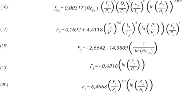
In the same way, the f factor is
cal-culated for the low and high Reynolds
number. For Re lower 1000, flow is
cal-culated by equation 16 with exponents F1, F2, F3 and F4
extracted from equations 17 to 20.
f
low= 0,00317
(
Re
Dc)
F2
A0 At
( (
Fp Pl
( (
D F3h
Dc
( (
L F4h
Lp
( (
(
ln
(
- 6,0483
F
1= 0,1692
+ 4,4118
PPl t( (
Fp Pl
( (
LhLp
( (
(
ln
(
- 0,3 - 2
Fp Pt
( (
3F
2= - 2,6642 - 14,3809
(
ln
(
Re
1(
Dc)
F
3= - 0,6816
PFp l( (
(
ln
(
F
4= 6,4668
AA0 t( (
Fp Pt
( (
1,7(
ln
(
fhigh is found by equation 21 with exponents (F19, F20, F21, F22 and F23) of equation 22 to 26.
f
high= 0,06393
(
Re
Dc F5)
F6Fp Dc
( (
D F7h
Dc
( (
F8F9
Lh Lp
( (
N
(
ln
(
Re
Dc)
- 4
)
- 1,093F
5= 0,1395 - 0,0101
AA0 t( (
Fp Pl
( (
0,58(
ln
(
PlPt
( (
1,9Lh Lp
( (
-2F
6= - 6,4367
(
ln
(
Re
1(
Dc)
F
7= 0,05875
(
ln
(
Re
Dc))
F
8= - 2,0585
F
p(
ln
(
Re
Dc))
P
t( (
1,67F
9= 0,1036
PPl t( (
(
ln
(
The values of the output
vari-ables f and j are compared with the
experimental data obtained in (Wang
et al.,1998). After obtaining accurate
results for these variables, optimiza-tion of heat exchanger geometry is performed. The design variable (DV)
considered is the inclination angle of louver ins of domain, as used by
(Stephan, 2002; Ameel at al.,2012).
To execute the optimization study, the commercial code
De-signExplorer® from Ansys® is used,
selecting the the MOGA procedure;
This is an algorithm of evolutionary type, that uses natural selection to generate and choose geometry more eficiently, according to the estab-lished objective. There are seven DVs employed which are the ins angles, shown in igure 6.
314
(27) To generate the irst generation of
individuals, the design of experiments of type Optimal Space Filling was used, cre-ating 83 different geometries. The subse-quent generations are created selecting the best individuals of previous populations, chosen by maximization of the objective
function described below in equation 27. This expression allows recogniz-ing the global alterations that occurs within the domain, avoiding the use of locally deined factors. The temperature difference in the numerator is used because its augmentation means that
more energy was transferred to the cold chain. For the denominator, the pres-sure differential is used because there is an interest in reducing the pressure losses. So the G expression formed by these two quantities will be maximized by the optimizer algorithm.
G
=
Δ
T
Δ
p
3. Results of analysis
Through the expressions 3 to 23 and the Reynolds number obtained in simula-tion, the Colburn and Fanning factors are calculated and displayed in Figure 7. The curves of numerical results are exhibited
with the values obtained from correlations by (Wang et al.,1998).
In Figure 7, the red line represents the experimental data, the black lines represent the numerical values and the
green lines represent the experimental error variation of 15 % from the experi-mental test. The simulation reached good accuracy in relation to physical model by (Wang et al.,1998).
Figure 7
Comparison between
numerical and experimental data.
Flow fields and temperature distribution are displayed in Figures
8, 9 and 10, respectively. As can be seen, the points with more intense
turbulence are located in the vicinity of V-shaped ins.
Figure 8
Temperature distribution.
Figure 9
Figure 10 Speed distribution in domain.
To prove that the SST turbulence model is working correctly, Figure 11 shows the distribution of the mixing
func-tion values. When the mixing funcfunc-tion reaches values below 1, the model k - ω is executed along the wall and the model k -
ω in the rest domain. The blended function contour proves that k - ω model is executed near the wall as expected.
Figure 11 Blended Function.
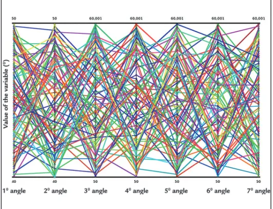
In Figure 12 is shown the pro-ile of the irst generated population using the statistical tool speciied in the text. Each broken line represents an individual and each vertical axis
represents the value of design vari-able. The intersection of break line and the vertical axis exhibit a value of this variable for that geometry. The chaotic appearance of this graph
dem-onstrated the variability of individuals in irst generation. A good variability of characteristics increases the chances of inding betters performances for heat exchangers.
Figure 12 Profile of first generated population.
After the optimization step, the 3 best geometries in all population gener-ated are found, with angles of each louver, exhibited in Table 2. The maximum
per-formance reached was a 25% increase of the objective function.
The analysis of sensibility of design variables in Figure 13, allowed to ind the
316
Figure 13
Analysis of DV sensibility.
Angles of
Lovers 1 2 3 4 5 6 7 [°C/Pa]G % increase
Individual
A 50.1 50.0 50.0 50.2 59,9 40.9 40.8 0.0046 25.61
Individual
B 50.0 50.0 50.0 50.4 58,4 40.6 40.1 0.00454 23.97
Individual
C 50.0 50.3 50.2 51.9 59.7 42.8 43.5 0.00439 19.87
Table 2
Values obtained
after optimization with 7 variables.
4. Conclusion
The methodology used in the present paper is eficient for the im-provement of the simulated component.
The SST turbulence model provided good results when compared to the experimental data and the MOGA
evolutionary algorithm provided an increase of approximately 25% for the objective function.
5. Acknowledgements
The authors fully acknowledge the support received from CNPq, FAPEMIG and UFSJ.
6. References
AMEEL, B., DEGROOTE, J., HUISSEUNE, H., JAEGER, P. DE, VIERENDEELS, J., PA-EPE, M. DE. Numerical optimization of louvered in heat exchanger with variable louver angles. Journal of Physics, Conference Series, v. 395, conferência 1, 2012.
HERCKERT, MATHEUS GUILHERME REIMANN. Fluidodinâmica computacional e suasaplicações. Uberlândia, MG, Fevereiro, 2004.
JIIN-YUH JANG, CHUN-CHUNG CHEN. Optimization of the louver angle and louver pi-tch for a louver inned and tube heat exchanger. International Journal of Physical Sciences, v. 8, n.43, p. 2011-2022, 2013.
MALISKA, CLÓVIS R. Transferência de calor e Mecânica dos Fluidos Computacional.
(2.ed.). Rio de Janeiro, RJ: LTC Editora, 2004.
MENTER, F. R. Two-equation eddy-viscosity turbulence models for engineering applications,
AIAA Journal, v. 32, n. 8. p. 1598-1605, 1994.
MICHAEL J. LAWSON. Practical applications of delta Winglets in Compact Heat Exchan-gers with louvered ins. Instituti Politécnico da Virgínia, 2006. (Master Dissertation). PERROTIN, THOMAS, CLODIC, DENIS. Thermal-Hydraulic CFD Study in Louvered
Fin--and-Flat-Tube Heat Exchangers. International Journal of Refrigeration, v. 27, p. 422-432, p.2004.
STEPHAN, RYAN A. Heat transfer measurements and optimization studies relevant to Lou-vered Fin Compact Heat Exchangers. Virginia, Blacksburg, 2002. (Master Dissertation in Mecanic Engeneer).
WANG, C. C., LEE, C. J., CHANG, C. T., LIN, S. P. Heat tansfer and friction correlation for Compact Louvered Fin and Tube Heat Exchanger. International Journal of Heat and Mass Transfer, v. 42, p.1945-1956, 1998.
WEBER, GUSTAVO CARDOSO. Análise experimental do desempenho termo-hidráulico de condensadores do tipo tubo-aletado. Universidade Federal de Santa Catarina, Florianópo-lis, 2007. (Dissertação de Mestrado).