425 REM: Int. Eng. J., Ouro Preto, 69(4), 425-433, oct. dec. | 2016
Abstract
Industrialized closing systems appear as rational solutions in steel-structured con-struction. These closing systems, consisting of multi-layered panels, have been applied in projects where it is intended to obtain a high sound transmission loss without raising the cost and without using a lot of mass. However, acoustic isolation depends on several factors, including the type of connection between the panels, requiring a preliminary study of the acoustic performance of the closing system to prevent future interventions. This paper uses a simpliied graphical method to evaluate the inluence of the type of connection (line-line, line-punctual or punctual-punctual) of industrialized closing panels on the estimation of the sound transmission loss that occurs across the wall constituted by these panels. The panels are combined, forming multi-layered closings interleaved by a layer of air, either without or with a sound-absorbing material between them. The results show that it is necessary to check the effectiveness of each type of fastening of the closing systems because, for example, for the frequency range between 500 and 2,000 Hz, the sound transmission loss of a closing system consisting of ce-mentitious plate with glass wool and line-punctual and punctual-punctual connections exceeds in 6.25% the sound transmission loss of the same system with line-line fasten-ing. For a system composed of expanded polystyrene with glass wool, the sound trans-mission loss provided by line-line fastening exceeds in 7.0% the sound transtrans-mission loss of the same closing system with line-punctual and punctual-punctual fastenings.
keywords: multi-layered closing systems, acoustical performance, sound transmission loss,
graphical method.
Rovadávia Aline de Jesus Ribas
Professora Efetiva
Universidade Federal de Ouro Preto - UFOP Escola de Minas
Departamento de Engenharia Civil Ouro Preto – Minas Gerais – Brasil [email protected]
Henor Artur Souza
Professor Titular
Universidade Federal de Ouro Preto - UFOP Escola de Minas
Departamento de Engenharia de Controle e Automação e Técnicas Fundamentais - DECAT Ouro Preto - Minas Gerais - Brasil
Influence of the type of
fastening of multi-layered
closing panels on the estimate
of the sound transmission loss
Mechanic and Energy
Mecânica e Energia
http://dx.doi.org/10.1590/0370-44672015690195
1. Introduction
The steel-structured construction technique has been increasingly applied, leading to projects that present a satis-factory overall performance. However, the fast assembling allowed by the steel-structured constructive systems requires the use of closing systems that have the same characteristics of prefabrication. The use of industrialized closing systems appears as a rational solution. But the choosing of the closing system for an edi-ice should be carefully made during its design phase because an improper choice may jeopardize the overall eficiency of the building and result in need of future interferences. Given this, it is important to analyze overall performance, includ-ing the checkinclud-ing of the thermal, acousti-cal and luminous comfort provided by
the prefabricated panels found on the national market of civil construction (Souza et al., 2007).
Despite the advantage of being lighter and more quickly erected than the traditional ones, industrialized closing systems have less mass, so their acousti-cal insulation capacity is questionable, leading to unfavorable comfort condi-tions (Garcia, 2004; Souza et al., 2007;
Roozen et al., 2015).
The acoustical comfort of the users of a building is obtained by reducing the noise in its interior to an acceptable level. The application of closing systems that provide an adequate sound transmission loss between environments can contrib-ute to a desirable acoustical insulation.
However, the study of sound
trans-mission across a multi-layered closing is complex, since it involves several param-eters. The sound insulation provided by a wall depends on several factors, such as the supericial density of its components, the thickness of the gap between the layers in multi-layered panels, and the existence (or not) of a sound-absorbing material in that gap. And, according to Bies and Hansen (2003), the way the panels are fastened also inluences on sound transmission, requiring a prelimi-nary study of the acoustical performance of the closing system, which considers the type of connection used between panels.
426
of the sound transmission loss that oc-curs across walls consisting of these panels, by applying a simpliied graphi-cal method. Closing systems are made up of cementitious plate panels, aerated
autoclave concrete, plasterboard and expanded polystyrene. Herein, studied were combinations of these industrial panels, inserted with a layer of air, mak-ing up closmak-ing systems with multiple
lay-ers, without or with a sound-absorbing material between hem. The evaluation also includes single closure systems con-sisting of massive precast concrete and ceramic brick masonry.
2. Materials and methodology
Sound transmission loss of a closing system may be obtained in laboratory tests or may be estimated by applying a simplified graphical method presented by Bies and Hansen
(2003) and Bistafa (2006), which is based on the study of Sharp (1973). For multi-layered closing systems, this study considers the type of mate-rial of the panels used to fabricate
the wall, the thickness of the air gap between them, the existence or not of a sound-absorbing material in the gap, as well as how the panels are fastened to each other.
2.1 Calculating the sound transmission loss
Sound transmission loss (TL), which
occurs when the sound reaches the other side of a wall with a smaller intensity than
the original, is a characteristic of the sound insulation provided by the closing system, and may be an indicator of its acoustic
performance (Bies and Hansen, 2003; Bistafa, 2006). Gerges (2000) presents Eq. (1), called the Law of Mass.
4
.
47
)
log(
20
=
f
M
TL
(dB)
(1)
(2)
where f is the frequency of the incident sound (Hz); M is the supericial density of wall material (kg/m²).
In a single-layered wall, the sound transmission loss is inluenced by the
frequency of the incident sound (f)
and shows different resonance and vibration behaviors as per its mass
and stiffness. Sound transmission loss across an isotropic panel (solid and homogeneous) may be obtained by standardized tests or may be esti-mated from the critical frequency (fc)
of an idealized model consisting of a panel of dimensions a, b and h, bending
stiffness Bs, and modulus of elasticity
E, using the Eq. (2) (Figures 1 and 2)
(Bistafa, 2006).
Figure. 1 Idealized model of a simply supported isotropic panel (Ribas, 2013).
Figure 2 Estimation of the TL across single isotropic panels (Bies and Hansen, 2003).
s c
B
M
c
=
f
2
2(Hz)
and
12
3
s
Eh
=
B
(N.m)
where fc is the critical frequency of
the panel (Hz); c is the speed of sound
in the air (m/s); M is the supericial
density of the panel material (kg/m2);
Bs is the bending stiffness of the panel
(N.m); E is the modulus of elasticity
of the panel material (N/m²), and h is the thickness of the panel (m).
Points A and B have coordi-nates (0.5 fc; TLA) and (fc; TLB),
re-spectively, which are calculated by the Equation (3).
0.5
Tr
an
smi
ss
io
n l
os
s (
dB
)
B A
log10(f/fc)
427 REM: Int. Eng. J., Ouro Preto, 69(4), 425-433, oct. dec. | 2016
TL
A= 20 log (f
c.
M) – 54
(dB) and
TL
B= 20 log ( f
c.
M) + 10
.
log – 45
(dB)
(3)(4)
where η is the panel internal damping
factor (dimensionless). The TL from point
B and fc is given by Equation (4), valid for f > fc, applied up to the frequency for which
the TL is equal to that calculated using the
law of mass or Equation (1).
45
10log
20log
c
f
f
+
M)
(f
=
TL
(dB)
Double-walled closing systems may produce a sound insulation greater than single-walled ones with the same thick-ness (Figure 3). Due to the complexity of the sound energy transmission ways between the panels, the soundprooing is not equivalent to the sum of the individual acoustic insulations. Bies and Hansen (2003) and Bistafa (2006) present a
sim-pliied graphical method, based on the analysis of Sharp (1973), for estimating the sound transmission loss across multi-layered walls, which considers the effects of the way the panels are fastened, which is determinant on their sound transmis-sion eficiency.
This graphical method consists in determining the coordinates of points A,
B and C, by means of Equation 5 to 11 (Table 1), and estimating the coordinates of point A' (Figure 4). In the formulation, the numeral 1 is associated with the panel that has the lowest critical frequency, and this frequency is, at most, equal to the critical frequency of the other panel, to which is associated the numeral 2 (Bies and Hansen, 2003; Bistafa, 2006).
Figure 3
Diagram of the closing systems with sound-absorbing material (Ribas, 2013).
T
rans
mi
ss
io
n l
os
s
(
d
B
)
C B
A’
A
Frequency (Hz)
f0 0.5fc2 fc2
Figure 4
Estimation of TL across
double walls (Bies and Hansen, 2003).
The two panels can be fastened to the same rafter or metallic proile, by means of resilient bars in order to reduce the transmission of mechanical vibrations. There are two usual ways of fastening, which generate four pos-sible combinations. When the panel is fastened directly to the rafter or metallic proile, a line of contact between these two elements is generated, forming the so-called in-line ixation (Figure 5a). Fastening by means of resilient bars is
called punctual ixation and the bars are attached to the rafters or metallic profiles by means of screws (Figure 5b). The spacing between the rafters or proiles (bc) are supposed to be uniform
and the spacing between screws (e) are
supposed to be uniform too. The four possible combinations of ixing are line-line (LL), line-punctual (LP),
punctual-line (PL), and punctual-punctual (PP),
where the irst panel is the one with the lower critical frequency (Bies and
Hansen, 2003; Bistafa, 2006).
In Table 1, f0 is the lowest resonant
frequency (Hz); TLi is in sound
transmis-sion loss at point i (dB); d is the spacing
between the panels or the gap thickness (m); Mi is the supericial density of panel i (kg/m2); f
ci is the critical frequency of
panel i (Hz); bc is the spacing between
rafters in in-line fastening (m); e is the
spacing between screws in punctual ix-ing (m), and ηi is the internal damping
factor of the material of the panel i.
Figure 5
Fastening the panels: in-line (a) and punctual (b) (Bistafa, 2006; Ribas, 2013).
428
Table 1
Coordinates of points A, B and C (Figure 4)
Equations
A (f0 ;TLA)
B (0,5 fc2; TLB)
C
(fc2; TLC)
2 / 1
2 1 0 80
M dM
M + M =
f
1
2
20log
20log
48
0
1
+
M
)
+
f
(M
=
2A
a) When there is no sound - absorbing material in the gap, TLB is equal to TLB1:
6 20log
0
f fc +
TL
TL
=
TL 1
A B1
b) When there is a sound - absorbing material in the gap, TLB is given by the highest value
between TLB1 and TLB2, TLB2 being:
i) line-line fastening:
77
1
20log
30log
10log
20log
1/21 2 / 1 2
1
+
c2 c 1 c 2
c B2
f
M
f
M
+
f
+
b
+
M
=
TL
ii) line-punctual fastening:
TL
B2=
20log
M
1e
+
40log
f
c 29
iii) punctual-punctual fastening:
105
1
20log
40log
20log
1 2 1
c 2 c 1 c 2
B 2
f
M
f
M
+
+
f
+
e
M
=
TL
1. For fc2 fc1: =TLB +10log 2+6
2. For fc2 = fc1 TLc =TLB+10log 2+5log 1+ 6
(5)
(6)
(7)
(8)
(9)
(10)
(11)
Point and coordinates
2.2 Evaluating the acoustical performance and panels studied
The closing panel capacity of loss in sound transmission is adopted as a criterion of acoustical perfor-mance. Standard NBR 15575 (ABNT, 2013) recommends the following minimum values of sound
transmis-sion loss between environments of a building (Table 2).
The panels under study were made of cementitious board (PLC), plasterboard (GEA), aerated autoclave concrete (CCA), expanded polystyrene
panels (EPS), massive precast concrete (PMC) or masonry (ATC), and these materials’ characteristics are shown in Table 3. Each panel is referred to by its material’s initials followed by its thick-ness in mm between parentheses.
Table 2 Minimum values of sound transmission loss between environments of a building
Element TL (dB)
Wall between autonomous housing units (gemination wall), where there is no dormi-tory; blind wall dormitories between a housing
unit and common areas of potential transit of people (hallways and stairways); and set of walls and doors of distinct units separated by
the lobby
45 – 49
Wall between autonomous housing units (gemination wall), where there is at least one dormitory; and blind wall between a housing unit and common areas where people may stay
50 – 54
Blind wall of rooms and kitchens between a housing unit and common areas of potential transit of people, like hallways and stairways
35 – 39
Multi-layered closings with and
without glass wool (LVI) as
sound-absorbing material in the air gap are presented in Table 4. The thickness of
the gap (d) is equal to 0.075m and the
429 REM: Int. Eng. J., Ouro Preto, 69(4), 425-433, oct. dec. | 2016
between screws (e) are both equal to
0.60 m. The coordinates of the points A, B and C, as shown in Figure 4, are calculated in order to draw the sound transmission loss curves as a function
of the frequency in the octave band (Table 4), for the three types of fasten-ing (LL, LP and PP). The combination
punctual-line was deleted from this study because, from a further analysis,
it was detected that the transmission loss associated to it is always less than the one of the combination line-punctual. The coordinates of point A’ are graphically determined.
Material h (m) ρ (kg/m3) E (N/m2) η υ B
s (N.m) fc (Hz)
PLC (10) 0.010 1,330 [1] 1.2x10⁸ [1] 0.005 0.20 83 21,158
GEA (12.5) 0.0125 750 [10] 2.0x10⁹ [4] 0.006 0.20 1389 3,113
CCA (100) 0.100 500 [10] 1.35 x 10⁹ [1] 0.015 0.15 115,090 390
EPS (100) 0.100 960 [4] 2.50 x 10⁶ [1] 0.005 0.08 210 12,670
PMC (100) 0.100 2,400 [10] 2.30 x 10¹⁰ [1] 0.020 0.20 1,996,528 205
ATC (150) 0.150 1,890 [10] 1.62 x 10¹⁰ [4] 0.005 0.15 4,661,125 146
Table 3
Characteristics of the materials of the panels.
PLC(10)-air(75)-PLC(10) PLC(10)-air(75)-GEA(12.5) CCA(100)-LVI(50)-air(25)-PLC(10)
PLC(10)-LVI(50)-air(25)-PLC(10)
PLC(10)-LVI(50)-air(25)-GEA(12.5) CCA(100)-air(75)-GEA(12.5)
GEA(12.5)-air(75)-GEA(12.5) PMC(75)-air(75)-PLC(10) CCA(100)-LVI(50)-air(25)-GEA(12.5)
GEA(12.5)-LVI(50)-air(25)-GEA(12.5)
PMC(75)-LVI(50)-air(25)-PLC(10) EPS(100)-air(75)-PLC(10)
CCA(100)-air(75)-CCA(100) PMC(75)-air(75)-GEA(12.5) EPS(100)-LVI(50)-air(25)-PLC(10)
CCA(100)-LVI(50)-air(25)-CCA(100)
PMC(75)-LVI(50)-air(25)-GEA(12.5) EPS(100)-air(75)-GEA(12.5)
EPS(100)-air(75)-EPS(100) CCA(100)-air(75)-PLC(10) EPS(100)-LVI(50)-air(25)-GEA(12.5)
EPS(100)-LVI(50)-air(25)-EPS(100)
3. Results and analysis
The results are shown in the charts of Figures 6 to 13. In Figures 6 to 9 are shown the results for clos-ings without and with glass wool, in which the two closing panels are equal (fc2 = fc1). In Figure 10 to 13 are shown
the results for closings with glass wool only, in which the irst panel is differ-ent from the second (fc2≠ fc1).
Closing systems without a
sound-absorbing material (glass wool) pres-ent, for the three types of fastenings (LL, LP and PP), the same sound
trans-mission loss curve. When glass wool is added, a change in behavior of the curve occurs according to the kind of fastening (Table 4, Figures 6 to 9). For the closings consisting of multi-layers of cementitious board, plasterboard and expanded polystyrene, the sound
transmission loss values rise with the use of glass wool (Figures 6, 7 and 9).
For closing of cementitious plate, the sound transmission loss rises to values above those provided by precast concrete and ceramic brick masonry closings (Figure 6). LP and PP
fastenings provide the highest values of sound transmission loss.
Table 4
Composition of the
430
125 250 500 1000 2000 4000
0 15 30 45 60 75 90
Frequency (Hz)
TL
(
d
B
)
LL, LP, PP -CCA(100) -air(75)-CCA(100) PMC(100)
LL, LP, PP -CCA(100) -LVI(50)-air(25)-CCA(100) ATC(150)
Figure 6 TL as a function of frequency – PLC without and with LVI (LL, LP, PP), PMC and ATC.
Figure 7 TL as a function of frequency – GEA without and with LVI (LL, LP, PP), PMC and ATC.
Figure 8 TL as a function of frequency – CCA without and with LVI (LL, LP, PP), PMC and ATC.
Figure 9 TL as a function of frequency – EPS without and with LVI (LL, LP, PP), PMC and ATC.
125 250 500 1000 2000 4000
0 15 30 45 60 75 90
Frequency (Hz)
TL
(
d
B
)
LL , LP, PP - PLC(10) -air(75)-PLC(10) LL - PLC(10) -LVI(50) -air(25)-PLC(10)
LP - PLC(10) -LVI(50) -air(25)-PLC(10) PP - PLC(10) -LVI(50) -air(25)-PLC(10)
PMC(100) ATC(150)
125 250 500 1000 2000 4000
0 15 30 45 60 75 90
Frequency (Hz)
TL
(
d
B
)
LL , LP, PP - GEA(12,5) -air(75)-GEA(12,5) LL - GEA(12,5) -LVI(50) -air(25)-GEA(12,5)
LP - GEA(12,5) -LVI(50) -air(25)-GEA(12,5) PP - GEA(12,5) -LVI(50) -air(25)-GEA(12,5)
PMC(100) ATC(150)
125 250 500 1000 2000 4000
0 15 30 45 60 75 90
Frequency (Hz)
TL
(
d
B
)
LL, LP, PP - EPS(100) -air(75)-EPS(100) LL - EPS(100) -LVI(50) -air(25)-EPS(100)
LP - EPS(100) -LVI(50) -air(25)-EPS(100) PP - EPS(100) -LVI(50) -air(25)-EPS(100)
PMC(100) ATC(150)
431 REM: Int. Eng. J., Ouro Preto, 69(4), 425-433, oct. dec. | 2016
125 250 500 1000 2000 4000 0
15 30 45 60 75 90
Frequency (Hz)
T
L
(
d
B
)
LL - CCA(100) -LVI(50) -air(25)-PLC(10) LL - CCA(100) -LVI(50) -air(25)-GEA(12,5)
LP - CCA(100) -LVI(50) -air(25)-PLC(10) LP - CCA(100) -LVI(50) -air(25)-GEA(12,5)
PP - CCA(100) -LVI(50) -air(25)-PLC(10) PP - CCA(100) -LVI(50) -air(25)-GEA(12,5)
PMC(100) ATC(150)
125 250 500 1000 2000 4000 0
15 30 45 60 75 90
Frequency (Hz)
T
L
(
d
B
)
LL - PLC(10) -LVI(50) -air(25)-GEA(12,5) LP - PLC(10) -LVI(50) -air(25)-GEA(12,5)
PP - PLC(10) -LVI(50) -air(25)-GEA(12,5) PMC(100)
ATC(150)
concrete and ceramic brick masonry closings (Figure 7). The expanded poly-styrene closing provides the highest val-ues of sound transmission loss, especially when the fastening is LL (Figure 9).
The sound transmission loss curves for cementitious plate, plasterboard and expanded polystyrene closings, in the frequency range of 500 to 2,000Hz, are completely or mostly in the region controlled by the law of mass (Figure 6, 7 and 9). For the closing of aerated autoclave concrete, neither the kind of fastening nor the use of glass wool inlu-ence the values of the transmission loss, which, in the frequency range consid-ered, are below the values obtained for the precast concrete and ceramic brick masonry closings, and are still in the re-gion controlled by coincidence (Figure 8).
For the same frequency range, most of the closings analyzed here comply with the criterion recommended by the standard NBR 15575 (ABNT, 2005) for sound transmission loss, which will be higher than 35 dB (Table 2). The clos-ings that do not meet the standard are composed of plasterboard without glass wool, at 500Hz and 2,000Hz frequen-cies (Figure 7), and aerated autoclave concrete with and without glass wool,
at 500Hz (Figure 8); both for all types of fastenings. The highest sound trans-mission loss value obtained was 80dB at 1,000Hz, for the LL-fastened closing of
expanded polystyrene with glass wool. This transmission loss was higher than the ones provided by LP and PP closings
in 5dB (Figure 9). The closing of cementi-tious plate with glass wool also provides a high value of sound transmission loss (65dB at 1,000Hz, with LP and PP
fas-tenings, which is 5dB higher than that with the LL fastening) (Figure 6), with
the advantage of being thinner (95mm) than the closing of expanded polystyrene (275mm).
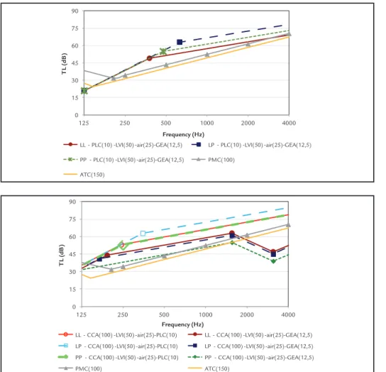
For the multi-layered mixed clos-ing composed of cementitious plate and plasterboard, with glass wool (Figure 10), the line-punctual fastening provides the highest values of sound transmis-sion loss. These values are closer to the values provided by the non-mixed cementitious plate closing than the ones obtained with the non-mixed plaster-board (Figures 6 and 7).
The aerated autoclave concrete closing, when applied with cementitious plate or with plasterboard, provides sound transmission loss values higher than the aerated autoclave concrete
non-mixed closing and, besides, may have its thickness reduced from 275mm to 185mm (Figure 11). At 1,000Hz, the highest value of sound transmission loss, 72dB, is provided by the closing of aer-ated autoclave concrete mixed with ce-mentitious plate, and with line-punctual fastening (Figure 11).
For the multi-layered mixed clos-ing composed of cementitious plate and plasterboard, with glass wool (Figure 10), the line-punctual fastening provides the highest values of sound transmis-sion loss. These values are closer to the values provided by the non-mixed cementitious plate closing than the ones obtained with the non-mixed plaster-board (Figure 6 and 7).
The aerated autoclave concrete closing, when applied with cementitious plate or with plasterboard, provides sound transmission loss values higher than the aerated autoclave concrete non-mixed closing and, besides, may have its thickness reduced from 275mm to 185mm. At 1,000Hz, the highest value of sound transmission loss, 72dB, is provided by the closing of aerated autoclave concrete mixed with cementi-tious plate, and with line-punctual fastening (Figure 11).
Figure10
TL as a function of frequency – PLC-GEA with LVI (LL, LP, PP), PMC and ATC.
Figure 11 TL as a function
432
125 250 500 1000 2000 4000 0
15 30 45 60 75 90
Frequency (Hz)
T
L
(
d
B
)
LL - PMC(75) -LVI(50) -air(25)-PLC(10) LL - PMC(75) -LVI(50) -air(25)-GEA(12,5) LP - PMC(75) -LVI(50) -air(25)-PLC(10) LP - PMC(75) -LVI(50) -air(25)-GEA(12,5) PP - PMC(75) -LVI(50) -air(25)-PLC(10) PP - PMC(75) -LVI(50) -air(25)-GEA(12,5) PMC(100) ATC(150)
125 250 500 1000 2000 4000 0
15 30 45 60 75 90
Frequency (Hz)
T
L
(
d
B
)
LL - EPS(100) -LVI(50) -air(25)-PLC(10) LL - EPS(100) -LVI(50) -air(25)-GEA(12,5)
LP - EPS(100) -LVI(50) -air(25)-PLC(10) LP - EPS(100) -LVI(50) -air(25)-GEA(12,5)
PP - EPS(100) -LVI(50) -air(25)-PLC(10) PP - EPS(100) -LVI(50) -air(25)-GEA(12,5)
PMC(100) ATC(150)
Figure 12 TL as a function of frequency – EPS-PLC, EPS-GEA with LVI (LL, LP, PP), PMC and ATC.
Figure 13 TL as a function of frequency – PMC-PLC, PMC-GEA with LVI (LL, LP, PP), PMC and ATC.
The expanded polystyrene clos-ing, when applied with cementitious plate or with plasterboard, provides sound transmission loss values lower than the expanded polystyrene non-mixed closing. Such decrease – 7dB for line-line fastening, at 1,000Hz – may be considered low, but, when mixed, the closing may also have its thickness reduced from 275mm to 185mm, as well (Figure 9 and 12). At
1,000Hz, the highest value of sound transmission loss, 77dB, is provided by the closing of expanded polysty-rene mixed with cementitious plate, and (Figure 12).
When mixed with cementitious plate, the multi-layered precast re-inforced concrete closing provides sound transmission loss values higher than when single, across all the fre-quency range considered, from 125
to 4,000Hz. When it is applied with plasterboard, punctual-punctual fastening and higher frequencies, the sound transmission loss stays in the region of coincidence and is lower. In this case, the highest sound transmis-sion loss value, 80dB at 1,000Hz, is provided by the precast concrete clos-ing mixed with cementitious plate, also with line-punctual fastening (Figure 13).
4. Final considerations
For most closings, the line-punc-tual fastening provides the highest values of sound transmission loss, fol-lowed by the punctual-punctual and the line-line fastenings (Table 5). It is necessary to analyze each multi-layered closing system and its behavior as per the three types of fastenings. For ex-ample, for the frequency range between 500 and 2,000Hz, sound transmis-sion loss provided by a cementitious plate closing with glass wool and line-punctual punctual and punctual-punctual fastening excels in 6.25% the sound transmission loss obtained by the same system with a line-line fastening; for a closing composed of
expanded polystyrene with glass wool, the sound transmission loss provided by the line-line fastening exceeds in 7.0% the sound transmission loss given by the same closing with line-punctual or punctual-punctual fastening.
Considering this same frequency range, in mixed closings, cementitious plate combinations with plasterboard, and cementitious plate with aerated au-toclave concrete, expanded polystyrene and concrete precast, with line-punctual fastening, provide sound transmission loss values higher than the other fasten-ings, and the largest difference occurs with aerated autoclave concrete (7%). It should be noted that when used with
cementitious plate or plasterboard the aerated autoclave concrete closing im-proves its acoustical performance. At 1,000Hz, this mixed closing provides a sound transmission loss 35dB (or 48%) higher than the one provided by the same closing when non-mixed.
433 REM: Int. Eng. J., Ouro Preto, 69(4), 425-433, oct. dec. | 2016 Closing system TL (dB) at 1,000Hz Closing system TL (dB) at 1,000Hz
Type of fastening → LL LP PP Type of fastening → LL LP PP
PLC(10)-air(75)-PLC(10) 39 39 39 PLC(10)-LVI(50)-air(25)-GEA(12.5) 57 67 62
PLC(10)-LVI(50)-air(25)-PLC(10) 62 67 67 CCA(100)-LVI(50)-air(25)-PLC(10) 67 72 67
GEA(12.5)-air(75)-GEA(12.5) 37 37 37 CCA(100)-LVI(50)-air(25)-GEA(12.5) 59 57 50
GEA(12.5)-LVI(50)-air(25)-GEA(12.5) 49 47 47 EPS(100)-LVI(50)-air(25)-PLC(10) 72 77 70
CCA(100)-air(75)-CCA(100) 37 37 37 EPS(100)-LVI(50)-air(25)-GEA(12.5) 65 61 65
CCA(100)-LVI(50)-air(25)-CCA(100) 37 37 37 PMC(75)-LVI(50)-air(25)-PLC(10) 77 82 73
EPS(100)-air(75)-EPS(100) 58 58 58 PMC(75)-LVI(50)-air(25)-GEA(12.5) 70 64 58
EPS(100)-LVI(50)-air(25)-EPS(100) 80 75 75
Table 5
Maximum values of TL depending on the type of fastening, at the frequency of 1,000Hz
5. Acknowledgments
The authors gratefully acknowledge the UFOP, the FAPEMIG and the CNPq, Brazil.
6. References
Associação Brasileira de Normas Técnicas, NBR 15220: Desempenho térmico de edi-icações, Rio de Janeiro, 2005. (in Portuguese)
Associação Brasileira de Normas Técnicas, NBR 15575: Edifícios habitacionais – De-sempenho, Rio de Janeiro, 2013. (in Portuguese)
BIES, D.A., HANSEN.C.H. Engineering noise control: theory and practice. 3th.
London and New York: Spon Press, 2003.
BISTAFA, S.R. Acústica aplicada ao controle de ruído. São Paulo: Edgard Blücher,
2006. (in Portuguese)
GARCIA, D.B. Análise do isolamento sonoro de sistemas construtivos residenciais
estruturados em aço. Belo Horizonte: Universidade Federal de Minas Gerais,
2004. (Dissertação de Mestrado em Engenharia de Estruturas). (in Portuguese). GERGES, S.N.Y. Ruído: fundamentos e controle. (2. ed.) Florianópolis, , UFSC, 2000.
(in Portuguese)
RIBAS, R.A.J. Método para avaliação do desempenho térmico e acústico de
edii-cações aplicado em painéis industrializados. (Tese de Doutorado em Engenharia
Civil). Ouro Preto: Universidade Federal de Ouro Preto, 2013. (in Portuguese) ROOZEN, N.B., MUELLNER, H., LABELLE, L., RYCHTÁRIKOVÁ, M.,
GLO-RIEUX, C. Inluence of panel fastening on the acoustic performance of light-wei-ght building elements: Study by sound transmission and laser scanning vibrometry.
Journal of Sound and Vibration. n. 346, p. 100-116, 2015.
SHARP, B.H. A study of techniques to increase the sound insulation of building ele-ments. Wyle Laboratories Report WR 73-S, Prepared for Department of Housing
and Urban Development, Washington, DC, Under Contract H-1095, 1973. SOUZA, H.A., NEVES, F.A., PEREIRA, C.C.G, SALES, U.C. Acoustical vibration
characteristics of prefabricated panels employed in industrialized construction.
Journal of the Brazilian Society of Mechanical Sciences and Engineering. v. 29,
n. 2, p. 152-161, 2007.