ABSTRACT: The design method presented in this paper is related to the upper-stage system and its instrumentation, expedition and facilitation so as to transfer the satellite from the destination orbit to the target orbit. We used an integrated design method with a structure based on multi-disciplinary system design optimization and developed a simple systematic interference method for designing aerospace products. The subsystems’ convergence in an optimized environment, matrix relationship, and integration of the subsystems’ parameters and presentation of design give results while meeting all requirements and considering the limitations of the design were the main aims of the research. Instead of a merely mathematical optimization design, in the present study a new design method with a systematic multipurpose optimization approach was designed. In this con- text, the optimization means the parameters are optimized as a result of the design convergence coeficients. Validation of the design method was not only obtained through comparison with a speciic product but also with the systematic parameters of all upper-stage systems with a similar operation through the results of statistical design graphs. The approximate similarities of the results indicate an acceptable and genuine design with a quite systematic approach which is better than an unreal and merely optimized design.
KeywoRdS: Upper stage, Systems design, Multidisciplinary design optimization, Systems integration.
Multi-Disciplinary System Design Optimization
of a Launch Vehicle Upper-Stage
Mostafa Zakeri1, Mehran Nosratollahi1, Alireza Novinzade2
INTRODUCTION
In a article named “Technologies for future precision strike missile systems - missile design technology” (Fleeman 2001), there is a survey of missile technology concepts, inluential parameters in design, and balance among subsystems, using new technologies with lower weight and cost communicating with the launcher. Overall configuration as well as missile simulation results from such a design method. he detailed explanations for the study are available in his book of Tactical Missiles Design. It needs to be mentioned that design depth is limited in the method yet the functional area is high while lack of integration and systemic communications implementation are the biggest weak points in this method which he explains and completes in his 2012 edition of the book. It is claimed in the study that all main parameters of a missile at conceptual design are taken into consideration while the missile has operational capability. Operational capability as well as systemic relation integration is the irst act in the current study.
he history of transition from classic design to modern design is not accountable in this study, however, some developed countries have been able to take advantage of system design and multidisciplinary optimization methods to improve conceptual design process through considerable savings in design time and costs (Olds 1993).
Brown and Olds (2006) surveyed multi-objective optimization techniques of collaborative optimization (CO), modified collaborative optimization (MCO), bi-level integrated system synthesis (BLISS), and all at once (AAO) on a reusable satellite. The study claims that the best design method cannot be chosen since such activities are for research
1.Space Research Institute – System Engineering Department – Space System Design Laboratory – Tehran/Tehran – Iran. 2.Khaje Nasir Toosi University of Technology – Faculty of Aerospace – Systems Division – Tehran/Tehran – Iran.
Author for correspondence:Mostafa Zakeri | Space Research Institute – System Engineering Department – Space System Design Laboratory | Postal Address: 1316943551 – Tehran/Tehran – Iran | Email: [email protected]
purposes only and require various studies on the results. Systemic design activities are briefly mentioned in this study while most of the activities are focused on comparing 3 design techniques. In the final conclusion, a comparison is made among design methods based on running time as well as quality comparisons, which could be said that BLISS designed outputs have higher quality.
Balesdent et al. (2011) surveyed various multipurpose optimization methods in space systems design quantitatively. Various MDO methods to design satellite missiles are sur-veyed in the study and some features, such as strength, price calculations, lexibility and convergence speed and problem implementation are taken into consideration so as to select the most suitable design method in designing launch vehicle. Mathematical equations of optimization of every method as well as main proile of the algorithm with optimization activities of every method are mentioned briely. Selection of the optimal method to design space system based on the mission and va- rious situations such as implementation time, cost, complexity, etc. is the inal conclusion of the study (Balesdent et al. 2011). Riddle (1998) states that using MDO in designing complex systems comes with 2 obstacles. One of them originates from disconnected and nonlinear essence of design process most of mathematical optimization methods are facing. One other unattractive point of MDO methods is design teams’ unwillingness to use it and similarity of automatic decision-making with creative process of innovative design.
Tsuchiya and Mori (2002) claimed that in spite of the higher speed of MDO with parametric methods, and based on which studies are reported to improve system and des-tination optimization for reusable launch vehicles (RLV), they are still recognized unsuitable for space systems design, especially satellite-carrying missiles which are essentially more complicated in configuration steps and trajectory design.
The need to design with a systematic approach in addition to design implementation based on physics of an aerospace product attracts some researchers to optimized systematic design. Aldheeb et al. (2012) tried to create an optimized design for a Micro Air Launch Vehicle.
In the present study, optimization and trajectory design are done through a design algorithm with systematic approach to reduce payload mass. The look on functional design physics in the main algorithm of the article and model of subsystems is clear. Villanueva et al. (2013) used a systematic approach in an article to design solid fuel engine.
Conceptual design in the current study is optimized through a genetic algorithm.
It could be claimed that creation of a systematic approach and transforming MDO to multi-disciplinary system design optimization (MSDO) includes development of MDO methods which develops operational capability based on MDO. MSDO approach is available in a limited number of the articles.
According to Wronski and Gray (2004), one can verify a comprehensive MSDO implementation in a specific case in the Massachusetts Institute of Technology (MIT). The specific importance of the study is that it gives a true expression of MSDO systematic design, multipurpose optimization and an obvious process of the algorithm.
Additionally, design and multipurpose optimization of an aircraft was studied through implementation and integrated design tools so as to predict and optimize the implementa-tion and related expenditures of commercial aircrafts design and production with the aim of reducing the noise through accurate selection of configuration and mission parameters (Diedrich et al. 2006). After surveying some design samples, a brief look to upper stage activities are made.
Engine and trajectory design in Casalino and Pastrone (2010) is optimized simultaneously. Systematic design is brief in the study and it could be included among the optimization articles with systematic approach for propulsion engine.
An upper stage activity is presented with a brief look at upper stage engine of solid fuel engine (Casalino and Pastrone 2010). Adami et al. (2015) designed an upper stage performed through three forms of MDO. Mathematically, a detailed comparison among the three design methods is presented. he optimal proof of choice is surveyed mathematically.
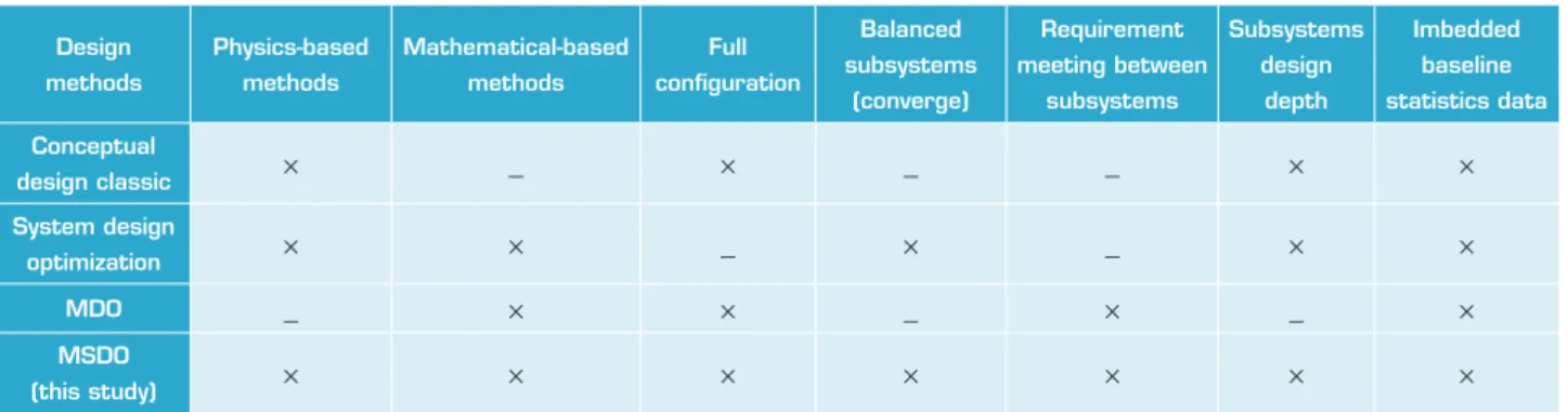
Ater considering the aforementioned articles in addition to their quantitative and qualitative analyses, Table 1 presents a summary of their features.
METHODOLOGY
Imbedded baseline
statistics data Subsystems
design
depth Requirement
meeting between
subsystems Balanced
subsystems
(converge) Full
coniguration Mathematical-based
methods Physics-based
methods design
methods
× ×
_ _
× _
× Conceptual
design classic
× ×
_ ×
_ ×
× System design
optimization
× _
× _
× ×
_ Mdo
× ×
× ×
× ×
× MSdo
(this study)
Table 1. Distribution of mass components.
presence of human expert in the Designing tool environment and integration of all designing subdivisions. The aim of this approach is the creation of sophisticated and advanced engineering systems that are competitive not only in terms of performance but also in terms of value of life cycle.
he most important properties of MSDO method can be stated as follows:
• Deal with design models of realistic size and idelity that will not lead to erroneous conclusions.
• Reduce the tedium of coupling variables and results from disciplinary models.
• Allow for creativity while leveraging rigorous, quantitative tools in the design process. Hand-shaking: qualitative versus quantitative.
• Data visualization in multiple dimensions.
• Incorporation of higher-level upstream and downstream system architecture aspects in early design: staged deployment, safety and security, environmental sustainability, platform design, etc.
In this procedure, design algorithm similar to other design algorithms is not of tree type or merely a mathematical optimization. he MSDO algorithm is designed to link all the subdivisions directly to each other and the best convergence is applied according to physics and subdivisions. In this way, the designer can easily put all the limitations and restrictions of design to work. In this paper, the concepts of design and multistep optimization are used in a strategic computing environment to design upper-stage which transfers from parking orbit to the target orbit. Presented parameters in this procedure are classiied as:
• Design or independent variables: including fuel mass ratio, engine structural mass ratio to the whole engine, etc.
• Simple limitations: including mass ratios, Isp, etc.
• Restrictions: diameter, orbital altitude, payload.
• Combined merit functions: aiming at minimizing the total mass and designing the best way of sending the satellite to the target orbit.
he most important speciications of the MSDO algorithm are as follows:
• Ofering new approaches in systematic design derived from MSDO designing method.
• Using statistical processing in the design process (increasing accuracy and rapid convergence).
• Ofering innovative convergence methods.
• Optimizing system and subsystems’ design parameters by using communication matrixes.
• Convergence of designing upper stage with previous stages of the rocket.
• Integrating all the design parameters and meeting all the restrictions and requirements.
• Ability to enter any new special requirement in the way of designing.
Algorithm design of upper stage includes the following:
• Statistical designing and analysing statistical data.
• Designing the layout of subsystems and subdivisions.
• Dynamics and trajectory design.
• Propulsion system design and tank design.
• Feeding system design.
• Analysis of mass-dimensions and mass associated with the previous stage of launch vehicle design.
• Structural design and stifener.
• Systematic analysis (coniguration, integrating and optimization).
environment. All the requirements and restrictions can be classiied as follows:
• he requirements of trajectory.
• he requirements of the launch vehicle and launch.
• he requirements of subsystems and subdivisions.
• he requirements of construction and assembly.
• he limitations in choosing the hardware.
Basic hypotheses regarding the design of upper stage are as follows:
• Payload.
• Parking orbit and target.
• Mechanical properties.
• Helium mechanical properties.
• he characteristics of the chosen fuel.
• Safety factors.
• Temperature of tanks and the lame.
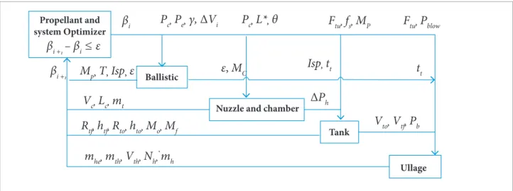
he main body of the communication among subsystems, within each other, and the system is created according to the design matrix. Design matrixes are the designer’s guide for displaying design communications and the effects of the parameters on each other (Peoples and Schuman 2003). The communicative matrix between the components of propulsion system is shown in Fig. 1 due to the importance
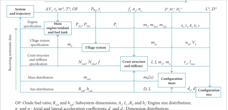
of the communication of the propulsion system components. he most important design matrix is the comprehensive design matrix which is shown in Fig. 2. Only the main parameters of design are mentioned in the matrixes.
In designing the MSDO algorithm, several optimization and convergences were used. he goal of optimization is to achieve the least amount of goal parameters; however, the goal of convergence is to converge all design parameters within each other as well as meeting all the requirements and limitations. Optimization includes:
• Optimizing comprehensive design matrix based on the MSDO and through genetic algorithm.
• Optimizing trajectory through genetic algorithm.
• Optimizing propulsion system through genetic algorithm.
• Optimizing total mass through genetic algorithm.
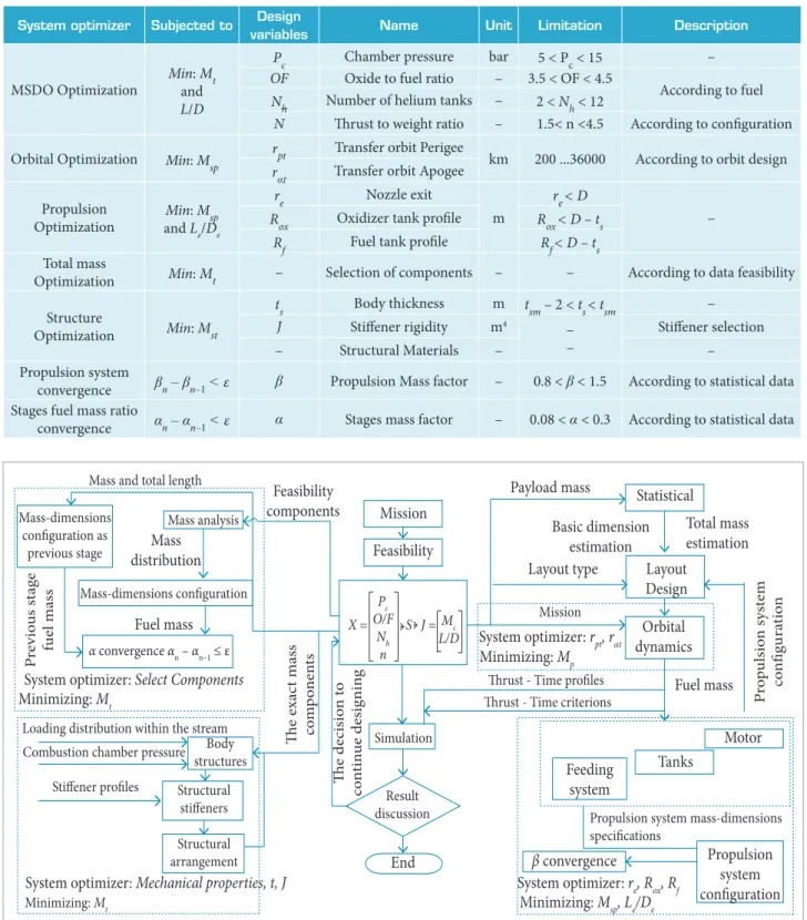
• Optimizing the thickness of the crust and stifener based on the buckling test and through genetic algorithm. In Table 2, one can see the above-mentioned optimization properties. Design convergence items in MSDO algorithm include the acceleration of design process according to the statistical equations (reducing the time while increasing accuracy).
Propellant and system Optimizer
Ballistic
Nuzzle and chamber
Tank
Ullage
β
i +1– β
i≤ ε
β
iP
c,
P
e,
γ,
∆
V
iP
c,
L*,
θ
F
tu,
f
s,
M
PF
tu,
P
blowt
tIsp,
t
tε
,
M
CM
p,
T
,
Isp
,
ε
V
c,
L
c,
m
tR
tf,
h
tf,
R
to,
h
to,
M
o,
M
f∆
P
hV
to,
V
tf,
P
bm
he,
m
th,
V
th,
N
h,
m
hPc and Pe: Chamber and exit pressure; Pblow: Blow tanks pressure; Ph: Distribution of the pressure gradient;
L*: Combustion characteristic length; ΔVi : Energy change in each burn tt:
Burn time distribution; Rt and ht : Radius and height of the tank; Vth and mth: Volume and mass of the helium tanks’
mh: Blow rate; Nh: Number of blowing tanks; Vto, Vtf and Vc: Fuel tank capacity oxidation and combustion;
ε: Expansion ratio; T and Isp: Thrust and specific impulse; Lc: Combustion chamber length;
Ftu: Yield stress; fs: Reliability factor; ts: Thickness of body structures; tsm: Maximum thickness of body structures.
β
i +1.
Mutation Crossover
Population Generations
Subjected to System optimizer
Uniform (0.2)
Scattered 100
100 Min: Mtand L/D
MSDO optimization
Uniform (0.2) Scattered
20 100
Min: Mp Orbital optimization
Uniform (0.2) Scattered
100 100
Min: Mspand Le/De Propulsion optimization
Uniform (0.2) Scattered
20 100
Min: Mt Total mass optimization
Uniform (0.2) Scattered
20 100
Min: Mst Structure optimization
Table 2. Optimization properties.
∆Vi, ti, m*, T*, OF
m0(x)
D, L dx, dy Rsub, hsub
Size distribution Mass distribution Crust structure
and stiffener specification Ullage system
specification
System and trajectory
Main engine/oxidant
and fuel tank
Ullage system
Crust structure and stiffener
Configuration size Configuration
mass
R
ecei
vin
g sys
tem
at
ic d
at
a
msub
fs, nx, ny
Pc
P0h, ti β*, Ms*, Mp* L*, D*
PTox, PTfu
mh
me, mTox, mTfu
mhe
Nxula, Nxhea, f
At, Lt, Rt, ht, ε
nth, Vb
I, J, mcr, mst tcr, lmax
Engine specification
.
.
OF: Oxide fuel ratio; Rsub and hsub: Subsystem dimensions; At, Lt ,Rt, and ht: Engine size distribution;
nx and ny: Axial and lateral acceleration coefficients; dx and dy: Dimension distribution;
m0(x) and msub: Mass distribution and mass of the subsystems; me and mT: Mass of the engine and of the tanks;
Nequ: Equivalent stress distribution; Vb: Volume of gas tanks.
Figure 2. Design correlations matrix.
(1)
(2)
(3)
(4) Primary values for design are obtained with statistical equations. Propulsion system convergence through propulsion system mass factor is dei ned as (Motlagh et al. 2013):
h e convergence of upper stage compared with the previous stage launch vehicle is:
In Fig. 3, it is presented the interference between convergence
β = M
s/
(
M
s+ M
p)
β
n= β
n – 1<
ε
α
=
M
p1/
M
p2α
n–
α
n – 1<
ε
Figure 3. Interference between convergence and optimization.Subjected to : Minimizing:
Initi
al
input
!" #$%&#'
ing: ( )*&+" , "
-Propulsion system algorithm
0
!
System optimizer:!",!#$%&#'
()*&+"-, System optmizer: re, Rox, Rf
Subjected to: minimizing Msp, Le/De
βn – βn–1 ≤ ε
Y
N βn
βn
β
0
Propulsion system algorithm
In
iti
al
inp
u
and optimization of the algorithm (Fig. 4). Design variables are described in Table 3.
Design output includes the following:
description Limitation Unit Name design variables Subjected to System optimizer – 5 < Pc < 15
bar Chamber pressure Pc
Min: Mt and L/D
MSDO Optimization OF Oxide to fuel ratio – 3.5 < OF < 4.5 According to fuel 2 < Nh < 12
– Number of helium tanks Nh
According to coniguration 1.5< n <4.5
– hrust to weight ratio N
According to orbit design 200 ...36000
km Transfer orbit Perigee rpt
Min: Msp Orbital Optimization
Transfer orbit Apogee rαt
– re< D
m Nozzle exit
re Min: Msp
and Le/De Propulsion
Optimization Rox Oxidizer tank proile Rox< D – ts
Rf< D – ts Fuel tank proile
Rf
According to data feasibility –
– Selection of components –
Min: Mt Total mass
Optimization
– tsm – 2 < ts< tsm
m Body thickness
ts Min: Mst
Structure
Optimization – Stifener selection
– m4 Stifener rigidity J – – Structural Materials –
According to statistical data 0.8 < β < 1.5
– Propulsion Mass factor β
βn – βn–1 < ε
Propulsion system convergence
According to statistical data 0.08 < α < 0.3
– Stages mass factor α
αn – αn–1 < ε
Stages fuel mass ratio convergence
Table 3. Design variables.
• Systematic parameters of upper stage.
• Subdivisions’ mass-dimension distribution.
• Systematic data of subdivisions.
Figure 4. MSDO algorithm.
Mass and total length Payload mass
Layout type
Mission
Thrust - Time profiles Thrust - Time criterions
Propulsion system mass-dimensions specifications P re v io u s st ag e fu el mas s Mass distribution Fuel mass Fuel mass P ro p u lsio n sys tem co nfigura tio n Basic dimension estimation Total mass estimation Feasibility components Th e exac t m a ss co m p o n en ts Mission Feasibility Simulation Statistical Layout Design Orbital dynamics Motor Tanks Feeding system
β convergence Propulsion system configuration Result discussion End Th e de ci sio n t o co n tin ue desig nin g Mass-dimensions configuration as previous stage Mass analysis Mass-dimensions configuration
α convergence αn – αn–1 ≤ ε
System optimizer: Select Components
System optimizer: Mechanical properties,t, J Minimizing: Mt
System optimizer: rpt, rαt Minimizing: Mp
System optimizer: re, Rox, Rf Minimizing: Msp, Le/De Minimizing: Mt
Loading distribution within the stream
Combustion chamber pressure Body structures
Stiffener profiles Structural stiffeners
Structural arrangement
However, the most important outputs of the algorithms include the following:
• Multidisciplinary optimization system.
• Adaptation of all design parameters.
• Meeting all the requirements and limitations.
deSIGN MeTHodoLoGy oF SUBSySTeMS
Statistical Design
Preliminary estimation of systematic parameters in upper stage design process is of utmost importance due to the following reasons: creating a basic coni guration for upper stage and faster convergence and more optimal design.
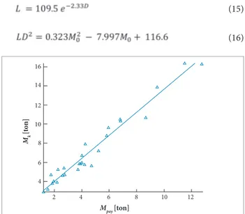
In statistical design via obtained data, the created population and needed graphs were extracted to create initial input (Mirshams and Khaladjzadeh 2010). For instance, 2 sample graphs are given in Figs. 5 and 6. h e payload mass is the i rst and the most important input in designing an upper stage.
Trajectory Simulation and Design
In this study, trajectory design (Fig. 7) is done based on Hahman’s approach as well as 2 references (Chobotv 1996; Curtis 2005).
where: Mk and Mpay are the i nal and payload mass. h e thrust to weight relative to burn time is represented by:
(5)
(7)
(8)
(9)
(10)
(11)
(12)
(13) (6)
Statistical equations are derived as follows: μp and μf payload mass ratio and dry mass ratio.
Figure 6. Thrust/weight versus burn time. Figure 5. Dry mass versus payload mass.
1 6
1 4
1 2
1 0
8
6
4
4
2 6 8 1 0 1 2
Mpay [ton] Mk
[t
o
n]
9
9
7
500 600 700 800 900 1000 1100
6
5 4
n [K
n/s]
t [s]
Parking orbit Target orbit Inclination change
Equipment's lifetime
Trajectory design
Trajectory design Number of reburns Amount of energy required
Trajectory time
Figure 7. Trajectory design algorithm.
(14)
(15)
(16)
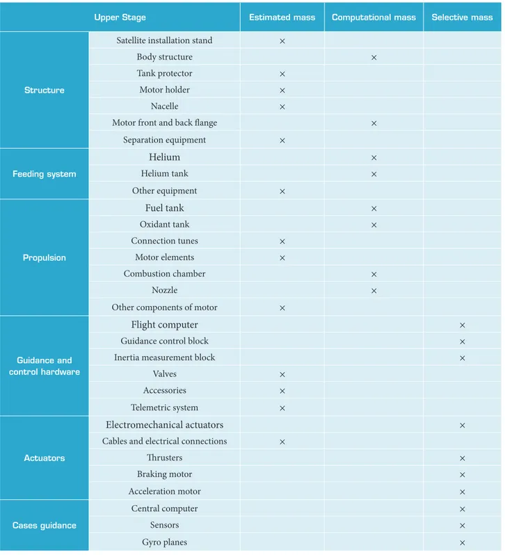
Mass Analysis
Upper Stage estimated mass Computational mass Selective mass
Structure
Satellite installation stand ×
Body structure ×
Tank protector ×
Motor holder ×
Nacelle ×
Motor front and back lange ×
Separation equipment ×
Feeding system
Helium ×
Helium tank ×
Other equipment ×
Propulsion
Fuel tank ×
Oxidant tank ×
Connection tunes ×
Motor elements ×
Combustion chamber ×
Nozzle ×
Other components of motor ×
Guidance and control hardware
Flight computer ×
Guidance control block ×
Inertia measurement block ×
Valves ×
Accessories ×
Telemetric system ×
Actuators
Electromechanical actuators ×
Cables and electrical connections ×
hrusters ×
Braking motor ×
Acceleration motor ×
Cases guidance
Central computer ×
Sensors ×
Gyro planes ×
mass of the same rocket block represents the similarity of mass ranges of the whole subsystems and their subcategories in each block with the same objectives. Thus, determining mass ranges of the main subcategories based on the main effective parameters is viable. In Table 4, all the objects
and the way to achieve them are illustrated. Final mass of the upper stage is achieved via the table and considering all the mass parameters. The final mass of upper stage can be achieved with all mass parameters presented in Table 4.
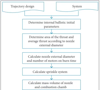
Propulsion Subsystem Analysis
Different specifications of a space propulsion system with other propulsion systems of a rocket are summarized as
(Friedman and Kenny 1965):
• Different outside conditions (space conditions).
• On-Of numbers (based on the trajectory design).
• Less thrust-to-weight ratio.
• h e use of pressure feed system (high accuracy but low thrust) (Sutton and Biblarz 2001).
Figure 8 shows the propulsion analysis algorithm.
After propulsion system design convergence, the amount of optimal fuel mass in every engine-on status is achieved. In the present study, the optimal propulsion system design is achieved through converging the structural convergence factor (). Using upper stage mass in every design loop,
all subsystems’ propulsion design is achieved and then the new value for fuel mass and convergence factor is obtained.
Trajectory design System
Determine internal ballistic initial parameters
Determine area of the throat and average thrust according to nozzle
external diameter
Calculate nozzle external diameter and number of motors on burn time
Calculate sprinkle system
Calculate mass-volume of nozzle and combustion chamb
Figure 8. Propulsion sub-algorithm.
Propulsion System Convergence
In the i rst design loop, the amount of fuel mass and the i nal mass of upper stage in every burning is calculated through the following equations:
(17)
(18)
(19)
(20)
(21)
(24)
(25) (22)
(23) where: j is the integration loop counter design; Msh, Mse, and MsT are dry mass of subsystems. h e equation for convergence coeffi cient (β) is dei ned as follows:
Propellant tanks:
h e internal relations of the propulsion system are shown in Fig. 1.
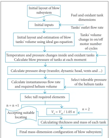
Feeding System Analysis
Controlling pressure in fuel tanks is easily possible using the pressure system feed. Furthermore, the simplicity of adjusting pressure in pressure system feed determines its high reliability, thus the process of switching and l ow control is easily possible. Output l ow could be controlled with installing a heater or pressure control valves. Generally, the concurrent process of disembarkation of capsules containing compressed gas and i lling propellant tanks could be shown via Eqs. 24 and 25 (Huzel et al. 1992).
High-pressure tanks (capsules):
where: Q is heat transfer between the gas blowing and its environment; Z is the gas compressibility factor; V is the volume control; T is the temperature; P is the pressure; m .i . m .d are blowing gas mass l ow rate input and output volume control; hi and hd are blowing gas enthalpy entry and exit control volume. h e sub-algorithm of feeding system is shown in Fig. 9.
(26)
(27)
(29)
(28)
Initial inputs Initial layout of blow
subsystem
Fuel and oxidant tank dimensions
Temperature and pressure changes inside and oxidant tanks
Calculating blow pressure to tanks at each moment
Calculating pressure drop (transfer, dynamic head, vents
and …)
Initial layout and estimating blow tanks volume using ideal gas equation
Calculating instantaneous flow rate and required
helium volume
Tanks volume change in on/off motor number of
cycles
n=2
th V
V =
Accepting suitable
Selecting tolerable pressure of the helium
tanks
n=n+1
Selecting all required elements
Tanks outlet flow rate Initial layout of blow
subsystem
Initial inputs
n = n +1
Accepting suitable locating
Vh = Vth / 1.05 n
Calculating thickness and mass of each tank
Final mass-dimension configuration of blow subsystem
n = 2 Initial layout and estimation of blow
tanks' volume using ideal gas equation
Temperature and pressure changes inside and oxidant tanks Calculate blow pressure of tanks at each moment
Calculate pressure drop (transfer, dynamic head, vents and ...)
Calculate instantaneous flow rate and required helium volume
Selec tall required elements
Select tolerable pressure of the helium tanks
Tanks' volume change in on/off
motor number of cycles Fuel and oxidant tank
dimensions
Tanks' outlet flow rate
Figure 9. Blow system sub-algorithm.
Volume, thickness, and the mass of every helium tank is obtained from the following equations (Humble et al. 1995):
where: Vh, tG and Mh are volume, thickness, and mass of blowing tanks; σhw and ρhw are the mechanical properties.
According to blow subsystem sub-algorithm, numbers of blow tanks are selected considering coni guration and layout. h e i nal mass of feeding system is calculated by the following equation:
Tanks Analysis
h e shape of the tank is a function of weight, leakage rate, tank volume, and locating restrictions. Spherical tanks have the best empty weight-to-loaded weight ratio (Hutchinson and Olds 2004). Tank design sub-algorithm is shown in Fig. 10. Other elements such as control valves are selected according to input pressure and l ow rate.
Figure 10. Tank design sub-algorithm.
Calculating required propellant volume calculating final tank mass
Selecting best layout and dimension design of tanks Recalculating final volume
Mixing ratio and types of propulsion
Shear and compressive forces during time
Checking all effective requirements in volume and structure of tanks
Check all effective requirements in volume and structure of tanks
Calculate required propellant's volume Calculate final tank's mass
Select the best layout and dimension design of tanks Recalculate final volume
Shear and compressive forces during time
Calculate final pressure and thickness of the propellant tanks
Calculate final mass and configuration of the tanks
Mixing ratio and types of propulsion
Structure Analysis
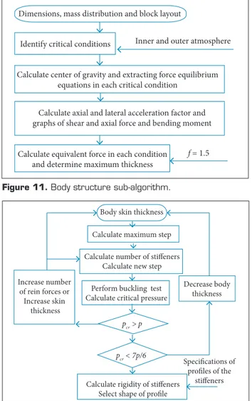
In structural analysis, providing stability and structural strength to deal with all external pressures is the main goal. In order to determine the mass of the structure, at i rst, the loads on each section of the structure shall be determined via dif erent stages of preparation to the end of the l ight. Loads on each section mean axial force, shear force and bending torque which is applied under external loads during structure mission. Critical load for each section is occurred based on existing experiences in any of the selected above stages. Loading sub-algorithm and the thickness of the body structure is shown in Fig. 11.
(3 0 )
(3 5 )
(3 6 ) (3 1 )
(3 4 )
(3 2 )
(3 3 )
where: N is the axial force; M is the bending moment. According to the critical situation exerted on the upper stage structure, lateral sti eners with low number could be used to strengthen body structure. Design algorithm for strengthening stif eners is shown in Fig. 12.
Stif ener rigidity and then the shape of the stif ener proi le can be selected through the following equation:
Calculate center of gravity and extracting force equilibrium equations in each critical condition
Calculate axial and lateral acceleration factor and graphs of shear and axial force and bending moment
Calculate equivalent force in each condition and determine maximum thickness
f = 1.5 Dimensions, mass distribution and block layout
Inner and outer atmosphere
Identify critical conditions
Body skin thickness
Calculate maximum step
Calculate number of stiffeners Calculate new step
Increase number of rein forces or
Increase skin thickness
Perform buckling test Calculate critical pressure
pcr > p
pcr < 7p/6
Calculate rigidity of stiffeners Select shape of profile
Specifications of profiles of the
stiffeners
Decrease body
thickness
Figure 12. Stiffener structure sub-algorithm. Figure 11. Body structure sub-algorithm.
where: J is the rigidity stif ener.
Dimension Design
Dimension design is achieved with 2 dif erent assumptions which, in one, upper stage diameter was determined and, in the other, it was calculated in the output. h e calculation of the length and diameter can be achieved through the following equation:
RESULTS
SAMPLe SoLUTIoN
A sample solution for upper stage design is presented in this section to generally introduce the design method:
1. Mission dei nition
• Payload mass is 1.5 tones with parking orbit which is 200 KMs and destination orbit is 36000 KMs with inclination of 45 degrees change.
• Other design inputs are based on requirements and limitations.
2. Results of supplying design initial inputs are shown in Table 5.
Input variable Values
β 0.162
T (kn) 48.36
μp 0.75
MP(ton) 10.23
MF(ton) 3.47
M0(ton) 13.70
Table 5. Initial input.
3. Trajectory design:
• Hohmann’s transfer (3 times Re burn).
Parameter name Values (kg)
Control block 245.88
Actuators 94.56
Cables 113.48
Body 189.1397
Telemetry 151
Stand 150
Disposal system 60
Engine maintenance 28.28
Control segments 18.91
Long tube 31
Flanges 28.28
Separation 75
Gyro planes and IMU 35
Table 9. Other components mass distribution.
4. Determining material and construction inputs of the subsystem:
• Used mechanical properties, environmental conditions, used luid properties.
• Determining fuel and oxidizer (hydrogen/oxygen). 5. Initial feasibility based on ability to transport about 13 tones to the parking orbit through stages of launcher rocket.
6. System design:
• Determining coniguration parameters according to Table 4.
• Selecting initial mass factor.
7. Propulsion design parameters (Table 6).
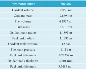
9. Design of tanks: mass and volume of tanks (Table 8).
Parameter name Input variable Values
hrust factor Cf 1.68
Nozzle expansion ratio ε 37
Speciic impulse Isp 326
Burning time tb(s) 680
hrust T (kn) 60
Propulsion low rate m . (kg/s) 20.52
Motor mass mm (m) 497
Motor diameter dm (m) 0.852
Motor length Lm (m) 2.04
Nozzle length Ln (m) 1.14
Nozzle outlet diameter de (m) 0.78 Table 6. Propulsion engine parameters.
8. Feeding system design (Table 7):
Parameter name Input variable Values
Blowing system mass mh(kg) 66
Cases blowing mass Mh(kg) 34.5
Helium mass mhe(kg) 20.6
hickness of helium tanks th(mm) 4.45
Radius of helium tanks rh(mm) 257
Number of helium tank Nh 6
Table 7. Feeding system parameters.
a. Selecting pressure-feed system.
b. Calculating pressure drop in fuel flow which is 3.2 bars and for oxidant is 4 bars.
c. Fuel tank pressure 11.2 bars and oxidant 12 bars.
Parameter name Values
Oxidant volume 7.050 m2
Oxidant mass 9.669 ton
Fuel volume 4.2827 m2
Fuel mass 3.581 ton
Oxidant tank radius 1.1895 m
Fuel tank radius 1.1895 m
Oxidant tank pressure 12 bar
Fuel tank pressure 11.2 bar
Fuel tank thickness 0.72257 m
Oxidant tank thickness 3.801 mm
Fuel tank thickness 3.5485 mm Table 8. Tank parameters.
10. Body structure: determining body thickness and stifener which requires determining critical modes properties of previous steps, fairing and types of stifener.
11. Mass distribution:
• Determining mass distribution (Table 9).
• Upper stage primary masses.
12. Upper stage mass and dimensions:
• Upper stage dimensions (Table 10).
Parameter name Values
Fuel mass 13.249
Final mass 3.391
Structure mass 1.891
Total mass 16.64
Table 10. Diameter and total length.
Parameter name Values
Dimensional ratio 2.7812
Diameter (m) 2.4921
Total length (m) 6.9314
Table 11. Mass parameters.
dIFFeReNT VARIANTS ANd VALIdATIoN
Technology for constructing a launch vehicle in countries varies from each other, however, the statistical graphs indicate the approximate similarity of systematic parameters for upper-stage systems. For instance, Fig. 13 shows the relationship of payload mass and dry mass in the upper-stage system. The real samples are circular and the samples derived from this paper for UDMH/N204 fuel are square-shaped. The comparative curve of burn time due to thrust/ weight is presented in Fig. 14. Convergence factors (α and
) are illustrated in Figs. 15 and 16.
The close similarity of these graphs is the main reason to validate the results derived from the study. At this point another validation was compared with Cent.D-5 upper-stage of Atlas V (401) which is presented in Table 12. Problem inputs: Mpay = 4.75 ton; D = 3.05m and Isp = 4378 N*s/kg.
Figure 13. Final mass versus payload mass .
12
8
4
0
0 1 2 3 4 5 6 7 8
Mf
[t
o
n]
Mpay [ton]
3 ,0 0 0
2 ,0 0 0
1,000
0
0 .5 2.5 4.5
n [N/kg]
t
[s
]
0.11
0.1
0.09
0.08
0.07
0.06
0.05
0 2 4 6 8 10 12 14 16
α
N u m b er of rounds design
0.15 0.14
0.13
0.12
0.11
0.1
0.09 0.08
0 2 4 6 8 10 12
Number of rounds design
β
Figure 14. Comparative curve of burn time due to T/W.
Figure 15. Convergence factor α.
Figure 16. Convergence factor .
CONCLUSION
D e s i g n p r o c e s s e s o f a l l e l e m e n t s a r e d o n e s i m u l t a n e o u s l y i n t h i s p a p e r. In each design loop, calculations become more accurate and results of each section, more suitable according to other systems. In this design method, a mistake can be found by system (because it afects all elements) and it would be easier to ix it. he main results are:
• Proportional with technology and ability for cons- truction.
• Logical relation of all segments and subsystems.
• Developing a national design and method.
• Presenting a sample upper stage according to diferent inputs.
• Logical convergence of parameters to logical values.
• Ability of performing general feasibility.
• Extensibility to accurate initial design.
• Ability of networking the design under supervision of the system.
• Designing systematic sample of upper stage.
• General guideline based on implementation of detail design (limitations of methods and range of parameters).
• All the important design points are specified in order to divide the algorithm for performing different projects.
AUTHOR’S CONTRIBUTION
Zakeri M has provided the article’s text; Nosratollahi M and Novinzade A carried out the guidance and control of the paper; the inal set was conducted by Zakeri M and Nosratollahi M; the idea was developed by all authors.
REFERENCES
Adami A, Mortazavi M, Nosratollahi M (2015) A new approach in multidisciplinary design optimization of upper-stages using combined framework. J Acta Astronautica 114:174-183. doi: 10.1016/ j.actaastro.2015.04.011
Aldheeb MA, Kafafy R, Idres M, Omar HM, Abido MA (2012) Design optimization of micro air launch vehicle using differential evolution. J Aerosp Technol Manag 4(2):185-196. doi: 10.5028/ jatm.2012.04020112
Balesdent M, Bérend N, Dépincé P, Chriette A (2011) A survey of multidisciplinary design optimization. Structural and Multidisciplinary Optimization 45(5):619-642. doi: 10.1007/s00158-011-0701-4
Brown NF, Olds JR (2006) Evaluation of multidisciplinary optimization techniques applied to a reusable launch vehicle. J Spacecraft Rockets 43(6):1289-1300. doi: 10.2514/1.16577
Casalino L, Pastrone D (2010) Optimal design of hybrid rocket motors
for launchers upper stages. J Propul Power 26(3):421-427. doi:
10.2514/1.41856
Chambers MC, Ardema MD, Patron AP, Hahn AS, Miura H, Moore MD (1996) Analytical fuselage and wing weight estimation of transport aircraft. NASA TM-110392.
Chobotv VA (1996) Orbital mechanics. Reston: American Institute of Aeronautics and Astronautics.
Crawford RF, Burns AB (1963) Minimum weight potentials for stiffened plates and shells. AIAA J 1(4):879-886. doi: 10.2514/3.1658
Curtis HD (2005) Orbital mechanics for engineering students. Oxford: Elsevier Butterworth-Heinemann.
Diedrich A, Hileman J, Tan D, Willcox K, Spakovszky Z (2006) Multidisciplinary design and optimization of the silent aircraft. Proceedings of the 44th AIAA Aerospace Sciences Meeting and
Table 13. Methods errors compared to the systematic data of Cent. D-5 upper stage system
design type method
Propellant weight [%]
dry weight [%]
Lift off weight [%]
Statistical 11.6 11.3 14.5
MSDO 0.2 2.1 3.66
0.27 0.182 0.109 3.61
Table 12.Comparation of validation to Cent D-5 upper-stage.
output data Mp (ton) M0 (ton) µf µp β n(N/kg)
System parameters Cent. D-5 19.65 26.78 0.266 0.18 0.10 3.64
Statistical design 16.8 23.66 0.29 0.2 0.11 3.88
Exhibit; Reno, USA.
Fleeman EL (2001) Technologies for future precision strike missile systems - missile design technology. Paper presented at: RTO SCI Lecture Series on Technologies for Future Precision Strike Missile Systems. Published in RTO-EN-018; Madrid, Spain.
Friedman PA, Kenny RJ (1965) Chemical pressurization of hypergolic
liquid propellants. J Spacecraft Rockets 2(5):746-753. doi:
10.2514/3.28273
Humble RW, Henry GN, Larson WJ (1995) Space propulsion analysis and design. New York: McGraw-Hill.
Hutchinson VL, Olds JR (2004) Estimation of launch vehicle propellant tank structural weight using simpliied beam approximation. Proceedings of the 40th AIAA/ASME/SAE/ASEE Joint Propulsion
Conference and Exhibit; Florida, USA.
Huzel DK, Huang DH, Arbit H (1992) Modern engineering for design of liquid-propellant rocket engines. Washington: American Institute of Aeronautics and Astronautics.
Mirshams M, Khaladjzadeh L (2010) Drivation of system level characteristics of a manned spacecraft by applying statistics models. Journal of Space Science and Technology 3(1-2):25-36. In Persian.
Motlagh JA, Novinzadeh AB, Zakeri M (2013) New approach in designing solid upper stage for interplanetary missions using inite burn assumption. IEEE Aero Electron Syst Mag 28(10):36-43. doi:
10.1109/MAES.2013.6642830
Olds JR (1993) Multidisciplinary design techniques applied to conceptual aerospace vehicle design (PhD thesis). Raleigh: North Carolina State University.
Peoples R, Schuman T (2003) A joint performance and inancial approach to aircraft design optimization; [accessed 2016 Sept 27]. https://dspace.mit.edu/bitstream/handle/1721.1/68163/16-888-spring-2004/contents/projects/6peoples_schuman.pdf
Riddle E (1998) Use of optimization methods in small satellite systems analysis. Paper presented at: 12th AIAA/USU Conference on Small Satellites; Logan, USA.
Sutton GP, Biblarz O (2001) Rocket propulsion elements. Lewiston: John Wiley & Sons.
Tsuchiya T, Mori T (2002) Multidisciplinary design optimization to future space transportation vehicles. AIAA-2002-5171.
Villanueva FM, Linshu H, Dajun X (2013) Kick solid rocket motor multidisciplinary design optimization using genetic algorithm. J Aerosp Technol Manag 5(3):293-304. doi: 10.5028/JATM.v5i3.225