ABSTRACT: In this paper, 12 new aerofoils with varying thicknesses for an aft-swept lying wing unmanned air vehicle have been designed using a MATLAB tool which has been developed in-house. The tool consists of 2 parts in addition to the aerodynamic solver XFOIL. The irst part generates the aerofoil section geometry using a combination of PARSEC and Bezier-curve parameterisation functions. PARSEC parametrisation has been used to represent the camber line while the Bezier-curve has been used to select the thickness distribution. This combination is quite eficient in using an optimisation search process because of the capability to deine a range of design variables that can quickly generate a suitable aerofoil. The second part contains the optimisation code using a genetic algorithm. The primary target here was to design a number of aerofoils with low pitching moment, suitable for an aft-swept lying wing coniguration operating at low Reynolds number in the range of about 0.5 × 10⁶. Three optimisation targets were set to achieve maximum aerodynamic performance characteristics. Each individual target was run separately to design several aerofoils of different thicknesses that meet the target criteria. According to the set of result obtained so far, the initial observation of the aerodynamic performance of the newly designed aerofoils is that the lift/drag ratio in general is higher than that of the existing ones used in many current-generation high-altitude long-endurance aircraft. Another observation is that increasing the maximum thickness of the aerofoil leads to a decrease in the maximum lift/drag ratio. In addition, as expected, this ratio sharply drops after the maximum value of some of these aerofoils.
KEYWORDS: Aerofoil design, Low Re, Swept lying wing.
Aerofoil Design for Unmanned High-Altitude
Aft-Swept Flying Wings
Ahmad Abdulkarim Alsahlan1, Thurai Rahulan1
INTRODUCTION
he light proiles of high-altitude long-endurance unmanned air vehicles (HALE UAVs), at high altitudes and moderate light speeds, represent low-Reynolds number operating conditions. he required lit coeicient is high when compared to more conventional lower-altitude aircrat, due to reduced air density. herefore, the aerofoil section needs to be optimised to generate high lit coeicients with a proile drag as low as possible. he pitching moment (Cm) should also be considered especially for the lying wing coniguration with no tail. An additional constraint in the selection of suitable aerofoil sections is the thickness required to hold fuel tanks or batteries and the required structural elements for adequate stifness. In previous literature, deferent aerofoils were selected on the basis of a high lit/drag ratio. he swept lying wing coniguration is not adopted widely in the literature for high altitude operation. Alsahlani et al. (2015) introduced a new at-swept lying wing solar powered UAV operating at 17 km altitude. An HS520 aerofoil was selected due to its low pitching moment and drag coeicient (Cd). Recently, in July 2015, the Facebook Company revealed its irst full-scale solar powered at-swept lying wing aircrat called Aquila, which is to be used to facilitate internet communications in remote parts of the world (he Guardian 2015). However, there is as yet no detailed information available about this aircrat. Selecting or designing an aerofoil for high altitude aircrat can be afected by several considerations that will be explained briely:
• Aircrat coniguration: stability requirement can afect the aerofoil selection process depending on the layout coniguration.
Unswept flying wing aircraft has no stabiliser. It depends on the pressure distribution along the
doi: 10.5028/jatm.v9i3.838
1.University of Salford – School of Computing, Science and Engineering – Department of Aeronautical Engineering – Salford – United Kingdom.
Author for correspondence: Ahmad Abdulkarim Alsahlani | University of Salford – School of Computing, Science and Engineering – Department of Aeronautical Engineering | Newton Building | Postal code: M5 4WT – Salford – United Kingdom | Email: [email protected]
chord-wise direction to achieve 0 pitching moment about its aerodynamic centre. his is achieved by the incorporation of a relexed the trailing edge in order to generate a negative lit force at the trailing edge, but at the cost of reducing the maximum lit coeicient and increasing the drag (Buckstrom 1979; Qin et al.
2004). NASA prototypes such as Helios, Centurion, and Pathinder are examples of this approach. At-swept lying wing aircrat uses an aerofoil with a less relexed trailing edge to reduce the reduction in the maximum lit coeicient (Cl���) since a combination of sweep-back and wash-out is used to supplement the generation of the balancing pitching moment. If the pitching moment is large, a huge amount of sweep or wash-out is needed. herefore, in general, aerofoils with a small pitching moment is preferable for tailless aircrat (Nickel and Wohlfahrt 1994). his approach has been used in manned lying wing aircrat such as the Northrop Grumman B-2 Spirit and the Horten series of aircrat (Mader and Martins 2012; Li et al. 2012). his approach will be the main focus of this paper. Tailed aircratcan use an aerofoil with high lit/drag ratio and the tail is used for stability but at the cost of additional drag from the empennage. QinetiQ Zephyr, Global Observer, X-HALE, and Boeing Phantom Eye are examples of this approach (Rapinett 2009). • Low Reynolds number: at low Reynolds number the
viscous effects are more dominant which generate high drag and at reduced maximum lit while at higher Reynolds number, the lit/drag ratio improves (Greer
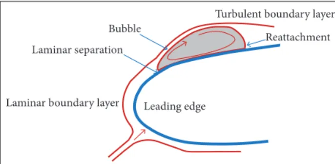
et al. 2000; Lissaman 1983). At low Reynolds number, the performance of an aerofoil is limited by quicker separation of the boundary layer. herefore, the low becomes quite unsteady causing the aerodynamic moment and forces to luctuate with time (Lei et al. 2013). A separation bubble may form within boundary layer causing the transition from laminar to turbulent, according to Fig. 1 (Lei et al. 2013; Lissaman 1983). he position of this separation bubble and the intensity depends on the shape of the aerofoil, angle of attack (AoA), and Reynolds number (Greer et al. 2000). his has the efect of reducing the gradient of the lit curve whilst increasing drag at the same time (Ma and Liu 2009). he majority of the air resistance comes from the pressure drag over the region of the laminar separation
bubble. Ater the separation bubble, the low reattaches to the aerofoil and becomes turbulent low or may stay separated. If it remains separated, the lit coeicient will sharply drop with a marked increase in the drag coeicient. his usually happens at a Reynolds number of about 70,000 (Hazra and Jameson 2007). Previous studies have shown that there is a critical Reynolds number at about 7 × 10⁴, where the performance of smooth aerofoils presents a noticeable change in the lit/ drag ratio. he smooth aerofoils have a higher lit/drag ratio than rough aerofoils at approximately more than Re > 105. hus, below this value, roughness is beneicial because this discontinuity in the surface can help to delay low separation (McArthur 2007).
• Stiffness of structure and internal volume needed: increasing aerofoil thickness can obviously increase the wing stifness and reduce wing bending moments sensitivity, which will result in reduced structural weight. Furthermore, it will also provide more space for fuel and payload (Cerra and Katz 2008). In general, thicker wing sections reduce both the maximum lit/drag ratio and the stall angle (Ma and Liu 2009).
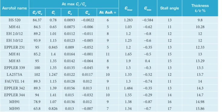
Table 1 shows the aerodynamic performance of some aerofoils which are designed for aft-swept and straight flying wing aircraft operating in low Reynolds environment. These results were generated using XFOIL at Re. Among these aerofoils, EPPLER 339 and LA2573A have the highest lift/ drag ratio and moderate maximum thickness-to-chord ratio (t/c %). Their stall angles seem to occur near the region where the lift/drag ratio reaches a maximum. LA2573A was used in high altitude prototypes such as Helios and Pathfinder aircraft, which sport straight wings (Kroo 1993). This aerofoil has a positive pitching moment to achieve the stability requirement without the need for either wing sweep or twist.
Figure 1. Structure of laminar separation bubble.
Laminar boundary layer Leading edge Laminar separation
Bubble
337 Aerofoil Design for Unmanned High-Altitude Aft-Swept Flying Wings
In case of using at-swept coniguration, much attention is paid to the pitching moment of the candidate aerofoil because of the absence of a horizontal stabilizer for stability purposes. Adopting this coniguration needs the use of an aerofoil with a smaller pitching moment, but not excessively low in order to obtain a high Cl. Since this coniguration has not been adopted in application of high altitude aircrat by the other designers as far as is known, this paper will investigate and design new aerofoils for the 3 aerodynamic targets. he expected operational Reynolds number that is appropriate to similar aircrat is about . In the literature, 2 main approaches are introduced to design aerofoils, which are based on direct numerical optimisation and inverse design. The common aspect between these 2 approaches is that the aerofoil shape is modiied until speciic goals are satisied. For the irst approach, the goals are usually the aerodynamic performances characteristic such as the lit, drag, and pitching moment coeicients, whereas the inverse design approach searches for an aerofoil shape until the requirements for particular low characteristic such as pressure distributions and skin friction are fulilled (Della Vecchia et al. 2014).
he aerofoil shape can be represented by several available parametrisation techniques such as the widely used B-splines, Bezier, and PARSEC parametrisations (Della Vecchia et al. 2014; Derksen and Rogalsky 2010; Salunke et al. 2014). he shape parametrisations can afect the optimisation search and
should represent a wide range of aerofoil shapes (Derksen and Rogalsky 2010). In the PARSEC parametrisation, the aerofoil surface can be represented by two curves, one for the upper surface and the other for the lower surface. Each curve can be represent using parameters linked directly to the commonly-deined aerofoil section geometry such as the maximum thickness and its location, radius of the leading edge, thickness and direction angle of the trailing edge. hese parameters should be selected carefully to achieve a reasonable aerofoil section, during the optimisation search, capable to be solved by the aerodynamic solver. he range of their values must be selected carefully in order to prevent unnecessary relex in the upper and lower surfaces generating unreasonable aerofoil shape thus delaying the convergence of optimisation. A methodology for this parametrisation is presented by Sobieczky (1997). Another popular parametrisation is called Bezier curve techniques, representing the aerofoil surfaces by two curves, one for upper surface and the other for lower surface, or one for camber line and the other for thickness distribution. Bezier curve can be designed with using its controlled point which deining the curves shape (Derksen and Rogalsky 2010; Park et al. 2008; Salunke et al. 2014). Several approaches aiming to enhance the trailing and leading edge shapes representation were introduced using multi curve with number of variables. he number of these curves and their
Aerofoil name
At max C
l /Cd
C
lmax Clmin Stall angle
Thickness
t/c %
C
l/Cd Cl Cd Cm At AoA ≈
HS 520 84.37 0.78 0.0093 −0.0022 6 1.283 −0.584 13 9.8
MH 61 84.5 0.65 0.0075 −0.006 5 1.03 −0.62 11 10.28
EH 2.0/12 89.2 1.01 0.0112 −0.011 8 1.2 −0.8 12 12
EH 3.0/12 93.9 1.15 0.0123 −0.005 9 1.25 −0.6 12 12
EPPLER 231 95 0.845 0.009 −0.052 5 1.2 −0.35 13 12.33
MH 81 85.2 1.4 0.0164 −0.001 11 1.65 −0.5 15 13
MH 83 95 1.35 0.0142 −0.064 8 1.9 0.4 15 13.29
EPPLER 339 100 1.35 0.0135 −0.045 9 1.5 −0.3 13 13.5
LA2573A 102 1.247 0.0122 0.0117 10 1.33 −0.52 12 13.7
FAUVEL 14 89.3 1.15 0.0128 0.012 9 1.3 −0.74 11 14
EPPLER 342 89.3 1.39 0.0156 0.013 11 1.484 −0.35 13 14.3
EPPLER 344 94 1.41 0.015 −0.032 10 1.55 −0.29 14 14.7
MH91 78.9 1.07 0.0136 0.012 9 1.38 −0.87 16 14.98
MH95 63.8 0.826 0.013 −0.007 7 1.34 −0.7 17 15.86
point’s coordinates can extremely afect the resolution and optimisation of time consumption (Della Vecchia et al. 2014; Salunke et al. 2014). Derksen and Rogalsky (2010) introduced a new aerofoil parametrisation (Bezier-PARSEC): the Bezier parametrisation which was used to represent the aerofoil edges, and the PARSEC approach to represent rest of the aerofoil surface. he aim was to enhance the matching of representing a wide number of existing aerofoils in addition to accelerate the speed converge of aerodynamic solver (Derksen and Rogalsky 2010). In this paper, the PARSEC parametrisation is chosen to represent the camber line of the aerofoil and the Bezier curve for the thickness distribution. his combination looks eicient as observed during the optimisation process and the generated aerofoils were reasonable.
AEROFOIL SHAPE OPTIMISATION TOOL
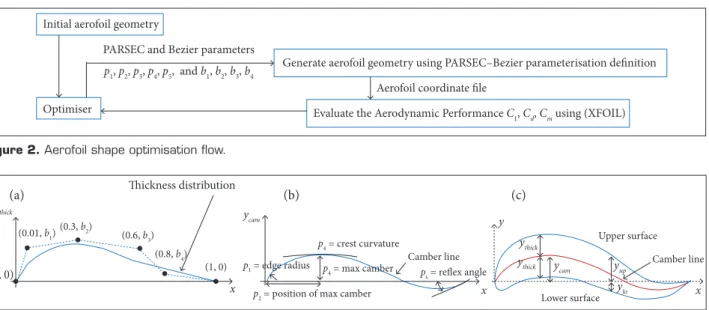
Numerous aerofoils of diferent thickness have been designed using a MATLAB tool, which has been coded as a part of this paper. his tool consists of 2 parts in addition to the aerodynamic solver (XFOIL), as shown in Fig. 2. he irst part generates the aerofoil section geometry using a combination of PARSEC and Bezier-curve parameterisation developed in this paper, involving 9 variables shown in Fig. 3. he second part contains the optimisation code using the canonical genetic algorithm, while several optimisation algorithms can be used within the MATLAB environment.
AEROFOIL SHAPE PARAMETERISATION
A combination of PARSEC and Bezier-Curve has been used to represent the aerofoil surface. In this paper, the PARSEC parametrisation is used to represent the camber line of the aerofoil, while the Bezier-Curve is used to represent the thickness distribution. he reason of using this combination is to achieve reasonable aerofoil geometries during the optimisation process and to prevent unconvergence problem of the aerodynamic solver, thus improving the time consumption and program stability. Moreover, by Bezier-Curve, the thickness distribution can easily be constrained to achieve a positive distribution, in addition to achieving a speciic maximum aerofoil thickness. As experience was obtained during this study, it has been found that this combination is eicient to search for the optimised setting because of its capability to deine a set of proper design variables leading to a rapid convergence.
Thickness Distribution
Bezier-Curve parametrisation has been used to represent the thickness distribution of the section, and the curve can be represented by associated control points. he generated curve passes through the irst and last control points, but does not need to pass through the other control points.
Assume a number of control points (n), with their coordinates
P(xci, bi), where bi will be denoted as Bezier parameters while
xci are set as in Fig. 3a. he curve can be discretised into a number of segments; each segment length will be denoted as (t),
Figure 2. Aerofoil shape optimisation low.
Figure 3. PARSEC-Bezier parametrisation deinition. (a) Bezier curve for thickness distribution; (b) PARSEC parameterisation for camber line; (c) Aerofoil surface.
Thickness distribution
(0.3, b2)
(0.01, b1) (0.6, b
3)
(0.8, b4)
(1, 0) Camber line Camber line
Upper surface
Lower surface ps = reflex angle
p4 = crest curvature
p4 = max camber
p2 = position of max camber p1 = edge radius
(0, 0)
x x x
y
ythick y
cam
ycam ythick ythick
ylo yup
(a) (b) (c)
Initial aerofoil geometry
PARSEC and Bezier parameters
Generate aerofoil geometry using PARSEC–Bezier parameterisation definition
Aerofoil coordinate file p1, p2, p3, p4, p5, and b1, b2, b3, b4
Optimiser Evaluate the Aerodynamic Performance C
339 Aerofoil Design for Unmanned High-Altitude Aft-Swept Flying Wings
where 0 ≤ t ≤ 1. he blending function of each segment can be evaluated by:
hen, the y-coordinates of the upper and lower surfaces can be calculated as shown in Fig. 3c by:
(1) (6) (7) (2) (3) (4) (5) (5)
-
The follows are the equations and t
B
in
=
i! n!n-i !1-
t
n-i
t
iand
(2)
×
Xthick
t
= x iB
in
t
i 1
and
(2)
×
and
Ythickt
bi
B
i
t
(2)
×
and
(2)
×
y u c m+ thick
l
-
thickand
(2)
! a
p "
i
# $ 5 % & '
.(
i-)
2
×
and
(2)
* ,
-/0
3 4
×
C6 7
and (2)
×
8 9:
;
< > ? @ A B
D E 0.5 F G H.5 I J K.5 L M N.5 O P Q.5 R S T UT
0.5 V.5 W.5 Z.5 [.5 \ ]\
^ _ ` d e -0.5
f g h j k
0.5
o q r s t v.5
w z{ | } ~.5 .5 .5 - -.5
-0.5 0.5 0.5 ¡ ¢ £ ¤.5 ¥ ¥ ¦ § ¨ ©.5
ª « ¬ ® ¯
, and (2) × , ° ±² ³ ´ µ ¶ · ¸ ¹º» ¼ ½¾ ¿ À Á Â Ã Ä (5)
he coordinates of each segment of the curve () associated with the given control points are found by:
and
where: Ythick represents the distribution of the half thickness of the aerofoil along the x-coordinate; Xthick represents the
x-coordinate of the upper and the lower surface.
Camber Line
PARSEC parameterisation has been used to represent the camber line of the aerofoil. In this paper, only 1 curve of the PARSEC parametrisation is taken. This curve can be represented by associated geometry parameters of the camber line (p1, p2, p3, p4, p5), as deined in Fig. 3b. According to the PARSEC methodology, the vertical coordinates of the curve at a given (x) coordinate location is given by:
he coeicients apa are calculated from the 5 parameters (p1, p2, ..., p5) of the aerofoil camber as follows:
where bpa ∧Cpa are evaluated from the following matrices:
herefore, the aerofoil surface will be deined regarding the Bezier and PARSEC parameters, with 9 variables: .
The Aerodynamic Solver
XFOIL has been used as the aerodynamic solver of the optimisation tool. It is a 2-D aerodynamic solver widely used in the design and optimisation of aerofoils due to its ability to produce good and rapid solutions that can be obtained to match experimental data. It is a combination of inviscid-viscous flow analyses where some approximations are performed. The input parameters of this solver are the aerofoil coordinates and the flow conditions, such as the AoA and Reynolds number.
Problem Formulation
he primary target was to design a number of aerofoils, with low pitching moment, suitable for an at-swept lying wing coniguration, operating at low Reynolds number of about 0.5 × 10⁶. hree optimisation targets were set to achieve maximum aerodynamic performance characteristics. Each individual target is run separately to design several aerofoils of diferent thicknesses that meet the target criteria. he set targets are:
• To achieve maximum lit/drag ratio with no less than a pitching moment coeicient of −0.05:
maximize (Cl /Cd)
subject: Cm > –0.05
• To achieve maximum lit/drag ratio with no less than a pitching moment coeicient of −0.02:
maximize (Cl /Cd)
• To achieve maximise (C1.5l /Cd) ratio with no less than a pitching moment coeicient of −0.05:
maximize (Cl 1.5/Cd)
subject: Cm > –0.05
he design variables of the optimisation problems are the PARSEC and Bezier parameters: p1, p2, p3, p4, p5, b1, b2, b3, b4.
In each design target, the thickness of the optimal aerofoil is constrained during the optimisation to ofer diferent aerofoils with diferent thicknesses. he constraining is done by controlling the upper and the lower bounds of the Bezier parameter values (b1, b2, b3, b4). he low condition was set at an AoA of 6° and Reynolds number of 0.5 × 10⁶.
NEWLY DESIGNED AEROFOILS
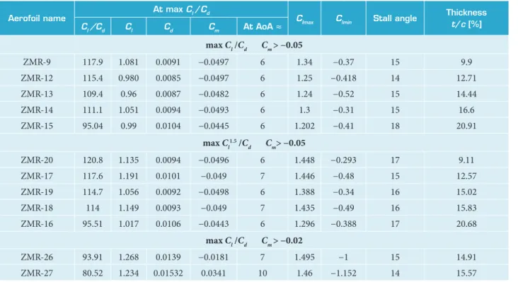
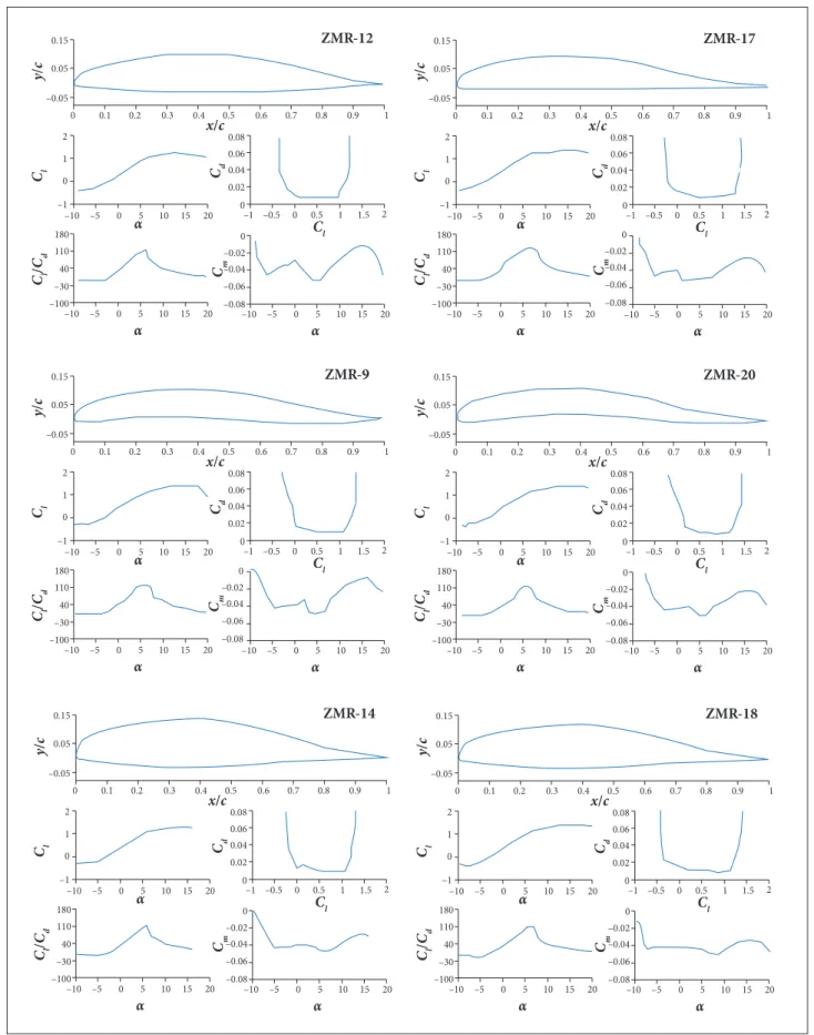
Table 2 shows the aerodynamic performance of the newly designed aerofoils at the maximum lit/drag ratio in addition to the maximum and minimum lit coeicients and stall angles. heir names and numbers are temporarily used at this stage of study and they have no other meanings. he shapes and aerodynamic characteristics of some of the newly designed aerofoils are shown in Fig. 4 at Reynolds number of 5 × 10⁵.
According to the set of results obtained so far, as tabulated in Table 2 and Fig. 4, the overall observations of the optimised aerofoils can be summarised as follows:
• The lift/drag ratios are higher than corresponding existing aerofoils presented in Table 1, and this is expected because the pitching moment of the new aerofoils is higher than of those in Table 1.
• Increasing the maximum thickness of the aerofoil leads to a decrease in the maximum lit/drag ratio. • For thicker aerofoils such as ZMR-16, ZMR-18, and
ZMR-19, the lift/drag ratio per AoA slops sharply drops ater the maximum value.
• he variation of the pitching moment with the AoA is not smooth in some of the optimised aerofoils, but this could be suspicious because the pitching moment of XFOIL results could be inaccurate. Other aerodynamic solver or experimental study will be needed to verify this behaviour. • he stall angles are not close to the angles in which
the maximum lit/drag ratio is achieved.
• Reducing the pitching moments result in reduction of the maximum lit/drag ratio and increased drag (see ZMR-26 and ZMR-27 in Table 2).
It is worth mentioning that the maximum Cl is not employed in the optimisation target and the focus was at an AoA of 6° for maximum lit/drag ratio away from the stall angle. herefore, most of the newly designed aerofoils would have stalled at about 8° from the angle corresponding to the
Aerofoil name
At max C
l /Cd
C
lmax Clmin Stall angle
Thickness
t/c [%]
Cl /Cd Cl Cd Cm At AoA ≈
max C
l /Cd Cm > −0.05
ZMR-9 117.9 1.081 0.0091 −0.0497 6 1.34 −0.37 15 9.9
ZMR-12 115.4 0.980 0.0085 −0.0497 6 1.25 −0.418 14 12.71
ZMR-13 109.4 0.96 0.0087 −0.0482 6 1.24 −0.52 15 14.44
ZMR-14 111.1 1.051 0.0094 −0.0493 6 1.3 −0.31 15 16.6
ZMR-15 95.04 0.99 0.0104 −0.0445 6 1.202 −0.41 18 20.91
max C l
1.5 /C
d Cm> −0.05
ZMR-20 120.8 1.135 0.0094 −0.0496 6 1.448 −0.293 17 9.11
ZMR-17 117.6 1.191 0.0101 −0.049 7 1.446 −0.48 15 12.57
ZMR-19 114.7 1.056 0.0092 −0.0498 6 1.388 −0.34 16 15.02
ZMR-18 114 1.149 0.0093 −0.049 7 1.435 −0.49 16 15.83
ZMR-16 95.51 1.017 0.0106 −0.0443 6 1.296 −0.388 17 20.68
max C
l /Cd Cm> −0.02
ZMR-26 93.91 1.268 0.0139 −0.0181 7 1.495 −1 15 14.91
ZMR-27 80.52 1.234 0.01532 0.0341 10 1.46 −1.152 14 15.57
341 Aerofoil Design for Unmanned High-Altitude Aft-Swept Flying Wings
Figure 4. Aerodynamic performance of the newly designed aerofoils at Re = 0.5 × 10⁶.
–1 0 0 –3 0 4 0 1 1 0 1 8 0
–5 0 5 1 0
–1 0 1 5 2 0
α
–5 0 5 1 0
–1 0 1 5 2 0
α
ZMR-14
C
l
x/c
y
/
c
–5 0 0
5 1 0 –1 0
–1 0 1 2
1 5 2 0 –1 –0 .5 0 .5 0 .1 0 .2 0 .3 0 .4 0 .5 0 .6 0 .7 0 .8 0 .9
1 .5 0
0 .0 2 0 .0 4 0 .0 6 –0 .0 5
0 .0 5 0 .1 5
0 .0 8
0 1 1 2 α Cl / Cd
Cl Cd
–0 .0 6 –0 .0 4 –0 .0 2 0
–0 .0 8
Cm
–1 0 0 –3 0 4 0 1 1 0 1 8 0
–5 0 5 1 0
–1 0 1 5 2 0
α
–5 0 5 1 0
–1 0 1 5 2 0
α ZMR-18
Cl x/c
y
/
c
–5 0 0
5 1 0 –1 0
–1 0 1 2
1 5 2 0 –1 –0 .5 0 .5 0 .1 0 .2 0 .3 0 .4 0 .5 0 .6 0 .7 0 .8 0 .9
1 .5 0
0 .0 2 0 .0 4 0 .0 6 –0 .0 5
0 .0 5 0 .1 5
0 .0 8
0 1 1 2 α Cl / Cd
Cl Cd
–1 0 0 –3 0 4 0 1 1 0 1 8 0
–5 0 5 1 0
–1 0 1 5 2 0
α
–5 0 5 1 0
–1 0 1 5 2 0
α ZMR-9
Cl x/c
y
/
c
–5 0 0
5 1 0 –1 0
–1 0 1 2
1 5 2 0 –1 –0 .5 0 .5 0 .1 0 .2 0 .3 0 .4 0 .5 0 .6 0 .7 0 .8 0 .9
1 .5 0
0 .0 2 0 .0 4 0 .0 6 –0 .0 5
0 .0 5 0 .1 5
0 .0 8
0 1 1 2 α Cl / Cd
Cl Cd
–1 0 0 –3 0 4 0 1 1 0 1 8 0
–5 0 5 1 0
–1 0 1 5 2 0
α
–5 0 5 1 0
–1 0 1 5 2 0
α ZMR-20
Cl x/c
y
/
c
–5 0 0
5 1 0 –1 0
–1 0 1 2
1 5 2 0 –1 –0 .5 0 .5 0 .1 0 .2 0 .3 0 .4 0 .5 0 .6 0 .7 0 .8 0 .9
1 .5 0
0 .0 2 0 .0 4 0 .0 6 –0 .0 5
0 .0 5 0 .1 5
0 .0 8
0 1 1 2 α Cl / Cd
Cl Cd
–1 0 0 –3 0 4 0 1 1 0 1 8 0
–5 0 5 1 0
–1 0 1 5 2 0
α
–5 0 5 1 0
–1 0 1 5 2 0
α ZMR-12
Cl x/c
y
/
c
–5 0 0
5 1 0 –1 0
–1 0 1 2
1 5 2 0 –1 –0 .5 0 .5 0 .1 0 .2 0 .3 0 .4 0 .5 0 .6 0 .7 0 .8 0 .9
1 .5 0
0 .0 2 0 .0 4 0 .0 6 –0 .0 5
0 .0 5 0 .1 5
0 .0 8
0 1 1 2 α Cl / Cd
Cl C
d
–1 0 0 –3 0 4 0 1 1 0 1 8 0
–5 0 5 1 0
–1 0 1 5 2 0
α
–5 0 5 1 0
–1 0 1 5 2 0
α ZMR-17
Cl x/c
y
/
c
–5 0 0
5 1 0 –1 0
–1 0 1 2
1 5 2 0 –1 –0 .5 0 .5 0 .1 0 .2 0 .3 0 .4 0 .5 0 .6 0 .7 0 .8 0 .9
1 .5 0
0 .0 2 0 .0 4 0 .0 6 –0 .0 5
0 .0 5 0 .1 5
0 .0 8
0 1 1 2 α Cl / Cd
Cl Cd
–0 .0 6 –0 .0 4 –0 .0 2 0
–0 .0 8
Cm
–0 .0 6 –0 .0 4 –0 .0 2 0
–0 .0 8
Cm
–0 .0 6 –0 .0 4 –0 .0 2 0
–0 .0 8
Cm
–0 .0 6 –0 .0 4 –0 .0 2 0
–0 .0 8
Cm
–0 .0 6 –0 .0 4 –0 .0 2 0
–0 .0 8
maximum lit /drag ratio. ZMR-26 and ZMR-19 are the most interesting aerofoils for the authors as they will be candidate for an at -swept aircrat due to their moderate thicknesses and the high maximum lit /drag ratios. h ey will be validated by a high order analysis solver in the next section.
COMPUTER FLUId dYNAMICS MOdEL
High-order Computer Fluid Dynamics (CFD) analysis has been conducted to validate some of the newly designed aerofoils using FLUENT ANSYS. Aerofoils ZMR-19 and ZMR-26 are selected to this study due to their moderate thickness intended to be adopted for a high altitude at -swept l ying wing coni guration in future work. A C-type mesh is adopted with a proper mesh density to ensure that Y+ of the i rst row of cells adjacent to the aerofoil surface is less than one. Figure 5 shows the schematic of a partial domain of ZMR-19. h e boundary conditions are the upper and the lower l ow domain boundary as a function of the velocity-inlet boundary whilst the downstream is considered as a pressure-outlet boundary. In addition, the aerofoil surface is considered as a wall. The SST k-ɷ (4eq) model, which can predict laminar-to-turbulent transition, is used due to its accuracy for a wide class of l ows (AnsysÅ 2013). h e
calculations are carried out at chord-base Reynold number of 0.5 × 10⁶.
RESULTS ANd dISCUSSION
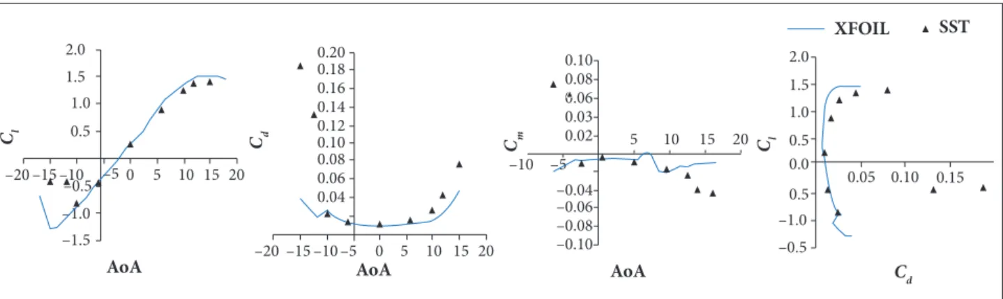
High-order analyses have been conducted to validate the aerodynamic performance of ZMR-19 and ZMR-26 aerofoils. The XFOIL predictions show that lift, drag, and pitching moment coei cients are in good agreement with FLUENT at low AoAs as shown in Figs. 6 and 7. However, at higher AoAs near the stall region, XFOIL predictions have not shown the same behaviour, especially the pitching moment coei cient.
Figures 8 and 9 show laminar separations (LS) of the ZMR-19 which occur at the upper and lower surfaces of the aerofoil at AoA = 0°. At an AoA equal to 6°, where the maximum lit /drag ratio is achieved, the LS of the lower surface has disappeared, while the separation bubble at the upper surface has slightly migrated forwards. Since the magnitudes of the velocity vectors within the bubble are small, the scales of the vectors shown in the i gures were set to 4.
h e l ow around the ZMR-26 aerofoil also shows similar behaviour as seen in the lower surface at AoA = 0° (Fig. 10). On the other hand, in Fig. 11, at an AoA of 6°, the LS has vanished, and the l ow remains attached all the way to the trailing edge. Nevertheless, the LS was also observed in existing aerofoils such as the LA2573A section, which is used in the NASA prototypes Helios and Pathi nder. h e velocity contour and vector for the l ow around the LA2573A section are shown in Figs. 12 and 13. Figure 12 illustrates the LS at the lower surface, which occurs at AoA = 0°. At 10°, where the maximum lit / drag ratio is achieved, the LS on the upper surface becomes noticeable as shown in Fig. 13.
Figure 5. Schematics of the partial domain of ZMR-19.
Figure 6. Aerodynamic performance of ZMR-19 aerofoil using SST k-ɷ (4eq) model and XFOIL at Re = 0.5 × 10⁶. 20
1.6 1.4 1.2 1.0 0.8 0.6 0.4 0.2
–0.6
–0.4 5 10 15
–5 –10
20 0.120
0.100
0.080
0.060
0.040
0.020
15 10 5
–5 0
–10
20
–0.090 –0.080 –0.080 –0.060 –0.050 –0.040 –0.030 –0.020 0.000
15 10 5 –5
–10
1.6 1.4 1.2 1.0 0.8 0.6 0.4 0.2
–0.6
0.05 0.1
–0.4 –0.20.0
XFOI L S S T
Cl
A o A
Cd
A o A
Cm
A o A
Cl
343 Aerofoil Design for Unmanned High-Altitude Aft-Swept Flying Wings
Figure 7. Aerodynamic performance of ZMR-26 aerofoil using SST k-ɷ (4eq) model and XFOIL at Re = 0.5 × 10⁶. 20
2.0 1.5 1.0
0.5
–0.5
–1.5 –1.0
15 10 5 0 –5 –15 –10 –20
20 0.20
10 15 5 0 –15 –10 –5 –20
0.18 0.16 0.14 0.12 0.10 0.08 0.06 0.04
20 0.10
15 10 5 –5
–10 0.08 0.06 0.03 0.02
–0.04 –0.06 –0.08 –0.10
2.0 1.5 1.0 0.5 0.0
–0.5
0.10
0.05 0.15
–1.0 0.5
X F OIL SST
Cl
AoA
Cd
AoA
Cm
AoA
Cl
C d
Figure 8. Velocity contour and vector at AoA = 0o of
ZMR-19 aerofoil.
Figure 10. Velocity contour and vector at AoA = 0o of
ZMR-26 aerofoil.
Figure 9. Velocity contour and vector at AoA = 6o of
ZMR-19 aerofoil.
Figure 11. Velocity contour and vector at AoA = 6o of
It is concluded that, at low Reynolds number, the LS could occur on both surfaces at small AoAs. As the AoA increases, LS bubbles either begin to disappear or move forward. The intensity of the predicted bubbles was small
and hence they are not expected to have pronounced effects on performance.
CONCLUSION
A number of new aerofoils with varying thicknesses for an aft-swept flying wing UAV, operating at low Reynolds number of about , have been designed using a developed aerofoil parametrisation employed in the optimisation tool. he aerodynamic performance of the newly designed aerofoil shows that the maximum lit/drag ratio is afected by the thickness-to-chord ratio. Increasing the maximum thickness of the aerofoil leads to a decrease in the maximum lit/drag ratio. In addition, as expected, this ratio sharply drops in value ater the maximum is reached. he stall angles of these aerofoils are not close to the corresponding angle of the maximum lit/drag ratio. LS, especially at small AoAs, was observed in the ZMR-19 and ZMR-26 aerofoils. However, this was also observed in existing aerofoils such as the LA2573A. Further optimisation processes and validation by experimental tests will be carried out within the discussed range of Reynolds numbers to instil conidence.
ACkNOwLEdgMENTS
he authors appreciate the Higher Committee of Education of Iraq (HCED-IRAQ) for supporting this study at the University of Salford.
AUTHOR’S CONTRIBUTION
Alsahlan AA conducted the study under the supervision of Rahulan T; both authors discussed the results and commented on the manuscript.
Figure 12. Velocity contour and vector at AoA = 0o of
LA2573A aerofoil.
Figure 13. Velocity contour and vector at AoA = 10o of
LA2573A aerofoil.
REFERENCES
Alsahlani A, Johnston LJ, Atcliffe PA (2015) Design of a high altitude long endurance lying-wing solar-powered unmanned air vehicle.
345 Aerofoil Design for Unmanned High-Altitude Aft-Swept Flying Wings
Ansys® (2013) ANSYS FLUENT theory guide; [accessed 2017 Apr. 25]. http://www.ansys.com
Buckstrom A (1979) The elements of tailless airplane design. Sport Aviation 5:39-44.
Cerra DF, Katz J (2008) Design of a high-lift, thick airfoil for unmanned aerial vehicle applications. J Aircraft 45(5):1789-1793. doi: 10.2514/1.36924
Della Vecchia P, Daniele E, DʼAmato E (2014) An airfoil shape optimization technique coupling PARSEC parameterisation and evolutionary algorithm. Aero Sci Tech 32(1):103-110. doi: 10.1016/j. ast.2013.11.006
Derksen R, Rogalsky T (2010) Bezier-PARSEC: An optimized aerofoil parameterisation for design. Adv Eng Software 41(7-8):923-930. doi: 10.1016/j.advengsoft.2010.05.002
Greer D, Hamory P, Edwards C, Krake K, Drela M (2000) Design and predictions for high-altitude (low Reynolds number) aerodynamic light experiment. J Aircraft 37(4):684-689. doi: 10.2514/2.2652
Hazra SB, Jameson A (2007) Aerodynamic shape optimization of airfoils in ultra-low Reynolds number low using simultaneous pseudo-time stepping. Aerospace Computing Lab (ACL) Report, 2007-4; [accessed 2017 Apr. 25]. http://aero-comlab.stanford.edu/Papers/lowren_paper.pdf
Kroo I (1993) Tailless aircraft design — recent experiences. Proceedings of the Symposium on Aerodynamics and Acoustics; New Jersey, USA.
Lei J, Guo F, Huang C (2013) Numerical study of separation on the trailing edge of a symmetrical airfoil at a low Reynolds number. Chin J Aeronaut 26(4):918-925. doi: 10.1016/j.cja.2013.06.005
Li P, Zhang B, Chen Y, Yuan C, Lin Y (2012) Aerodynamic design methodology for blended wing body transport. Chin J Aeronaut 25(4):508-516. doi: 10.1016/s1000-9361(11)60414-7
Lissaman P (1983) Low-Reynolds-number airfoils. Annual Review of Fluid Mechanics 15(1):223-239. doi: 10.1146/annurev.l.15.010183.001255
Ma R, Liu P (2009) Numerical simulation of low-Reynolds-number and high-lift airfoil S1223. Proceedings of the World Congress on Engineering; London, UK.
Mader C, Martins J (2012) Optimal lying wings: a numerical optimization study. Proceedings of the 53rd AIAA/ASME/ASCE/AHS/ ASC Structures, Structural Dynamics, and Materials Conference; Honolulu, USA.
McArthur J (2007) Aerodynamics of wings at low reynolds numbers (PhD thesis).Los Angeles: University of Southern California.
Nickel K, Wohlfahrt M (1994) Tailless aircraft in theory and practice. Washington: American Institute of Aeronautics and Astronautics.
Park K, Han JW, Lim HJ, Kim BS, Lee J (2008) Optimal design of airfoil with high aspect ratio in Unmanned Aerial Vehicles. Proceedings of the World Academy of Science: Engineering and Technology 42:182.
Qin N, Vavalle A, Le Moigne A, Laban M, Hackett K, Weinerfelt P (2004) Aerodynamic considerations of blended wing body aircraft. Progr Aero Sci 40(6):321-343. doi: 10.1016/j.paerosci.2004.08.001
Rapinett A (2009) Zephyr: a high altitude long endurance Unmanned Air Vehicle (Master’s thesis). Surrey: University of Surrey.
Salunke NP, Juned Ahamad RA, Channiwala SA (2014) Airfoil parameterization techniques: a review. Am J Mech Eng 2(4):99-102. doi: 10.12691/ajme-2-4-1
Sobieczky H (1997) Geometry generator for CFD and applied aerodynamics. Courses and Lectures - International Centre for Mechanical Sciences 366:137-158.