ABSTRACT: In this paper, a systematic method to synthesize parallel mechanisms for feed support mechanisms based on screw theory is proposed. First, the motion requirement of the feed support mechanism is studied. Then, a class of parallel mechanisms having a translational motion with different degrees of freedom is synthesized based on the constraint-synthesis method. Then, these parallel mechanisms are modiied based on the speciicities of deployable mechanisms, and two kinds of mechanisms are selected as the unit for the feed support mechanism. Finally, the deployment ratio of two kinds of mechanisms is optimized. The conigurations obtained in this paper can enrich the types of feed support mechanisms.
KEYWORDS: Feed support mechanism, Deployable mechanism, Structure synthesis, Deployment ratio, Parallel mechanism, Screw theory.
Structure Synthesis and Optimization
of Feed Support Mechanisms for a
Deployable Parabolic Antenna
Xiaoke Song1, Hongwei Guo1, Rongqiang Liu1, Zongquan Deng1
INTRODUCTION
Large deployable parabolic antennas are widely used on the aerospace equipment with the development of satellite communication technology (Sauder and Thomson 2014; Cherniavsky et al. 2004; Yurduseven et al. 2012). hey are composed of parabolic relector, feed, feed support mechanism, and so on. here are positive and ofset feed for the position of the feed in the parabolic antenna. he position accuracy concerns the properties of the antennas (Tayebi et al. 2013; Pour et al. 2014; Silver 1949). hus, for the feed support mechanism, it should present high precision, high stifness, large deployment ratio, simple structure etc. At present, there are several types of feed support mechanisms, such as robot arm, static truss and so on (Sauder and homson 2014).
This paper studies the feed support mechanism of an inlatable deployable parabolic antenna. As the support of the feed, the mechanism takes it to a predetermined position, so the mechanism only needs to carry out the translation motion in one dimension. Based on the requirements on the feed support mechanisms and the advantages of parallel mechanisms, such as high precision and high rigidity (Merlet 2006; Tsai 1999), we select the one dimensional parallel mechanisms as the research object and take structure synthesis and optimization for it. Regarding the structure synthesis of the parallel mechanism, lots of achievements have been obtained. Fang and Tsai (2002), Huang and Li (2002) and Xu et al. (2012) have used the screw theory to synthesize lots of parallel mechanisms. Li et al. (2004) synthesized the 3R2T 5DOF parallel mechanisms by Lie group. Gao et al. (2011) synthesized the parallel mechanisms with two
1.Harbin Institute of Technology – State Key Laboratory of Robotics and System – Harbin/Heilongjiang – China.
dimensional rotations. In this study, we have chosen screw theory to synthesize the parallel mechanisms.
he rest of this paper is organized as follows. Firstly, the inlatable deployable parabolic antenna is introduced, and the requirement of the feed support mechanism is given. Following, the constraint-synthesis method based on screw theory is briely introduced. hen, the structure synthesis of the mechanism is carried out. he resulted structures are modiied and one suitable type is selected. he deployment ratio of the selected structure is optimized next. At last, a conclusion is given.
MOTION REQUIREMENT FOR THE FEED SUPPORT MECHANISM
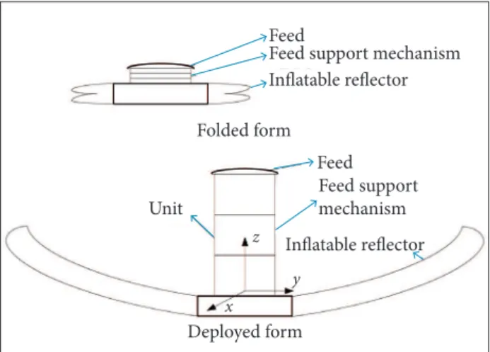
Figure 1 shows the studied inlatable deployable parabolic antenna. he antenna has two forms: folded and deployed. Regarding the feed support mechanism, it is composed of several deployable units serially connected. he unit should output a translation along the z-axis. It can also have motions in other directions. As parallel mechanisms have the advantages of high stifness and high precision, we selected parallel mechanisms as the unit. Based on the experience of practical engineering, we focused on the synthesis of parallel mechanisms with the degree of freedom (DOF) of 1Tz, 1Tz1Rz, and 1Tz2Rxy (the
numbers before T and R denote the number of DOF; T and
R denote the translational and rotational freedom separately; the right superscripts denote the direction of the motion). Because of the diiculties in driving and locking prismatic joints, we only used revolute joints in the structure synthesis. herefore, we considered the structure synthesis for parallel mechanisms with the DOF of 1Tz, 1Tz1Rz, and 1Tz2Rxy, which
have only revolute joints.
BASIC CONCEPTS AND THE CONSTRAINT-SYNTHESIS METHOD
In screw theory, a unit screw is deined as below:
Figure 1.The inlatable deployable parabolic antenna.
Feed
Feed
Unit
x y z
Feed support mechanism
Feed support mechanism Inflatable reflector
Inflatable reflector Folded form
Deployed form
where: s is a unit vector and denotes the direction of the screw axis; r is the position vector of any point on the screw axis; h is the pitch of the screw.
For a screw, $r = (s
r; s0r), and a set of screws, $1, $2, …, $n,
they are said to be reciprocal if they satisfy the condition:
where: represents the reciprocal product; $j represents the j-th screw.
We call the screw a twist if it represents an instantaneous motion of a rigid body. We call the screw a wrench if it represents a force and a coaxial couple acting on a rigid body. A force or a rotation can be given by (s; r × s), and a couple or a translation can be given by (0; s). In the synthesis process, the prismatic joint (P) outputs a translation, and the revolute joint (R) outputs a rotation. Other types of joints can be expressed as the combination of the two basic joints. For example, the spherical joint (S) can be expressed as three R joints intersecting at a point, but they are not coplanar; the universal joint (U) can be expressed as two intersecting R joints; the cylindrical joint (C) can be expressed as a P joint and a R joint which are concentric.
For the parallel mechanisms, if a set of screws represent the twists of one limb, then its reciprocal screws, $r1, $r
2
, ...,
$r
n
(n < 6) represent the constraint wrenches the limb exerted on the moving platform. hus the combination of these reciprocal screws of all limbs determines the constraints of the moving platform, and the motion twists of the moving platform are reciprocal to the combination of the constraint wrenches. his is the mathematical basis for the constraint-synthesis method. he process of the structure synthesis by constraint-synthesis method is shown as follows. First, the motion twists are obtained based on the motion requirement of the mechanism, then we get the constraint wrenches of the moving platform, which are reciprocal to the motion twists. Next, we distribute the constraint wrenches to each limb. hus we get the motion twists of each limb based on the constraint wrenches of the limb, as they are reciprocal, then construct the limb kinematic chain based on the motion twists. Finally, we assemble the limbs in
(1)
(2)
proper coniguration to guarantee that the combination of the limb constraint wrenches of each limb is equal to the constraint wrenches of moving platform.
STRUCTURE SYNTHESIS OF
PARALLEL MECHANISMS FOR FEED
SUPPORT MECHANISMS
he feed support mechanism is used to support the feed of antennas; it would sufer the interference from every direction, so the mechanism should have roughly the same load capacity on every direction. According to the experience on practical engineering and the load of feed support mechanisms, the mechanism should have three or four limbs, as more limbs make the manufacturing complicated and less limbs cannot get the uniform load capacity. So the objective in this study is to synthesize parallel mechanisms with three or four limbs composed of only revolute joints.
For the parallel mechanisms with one DOF of 1Tz, the twist
system of the moving platform is represented as:
Based on the reciprocal condition of screws, we then analyze the relation between a revolute joint and its constraint wrenches (Fang and Tsai 2002).
We deine three unit screws, $r = (w; r1 × w), $F = (f; r2 × f),
$C = (0 0 0; c), to indicate the revolute joint, constraint force and constraint couple, respectively, where w indicates the direction of the revolute joint; r1 indicates a point on the joint;
f indicates the direction of the constraint force; r2 indicates a point on the force; c indicates the direction of constraint couple. As the reciprocal product of revolute joint and constraint force is zero, as well as the reciprocal product of revolute joint and constraint couple, we have Eqs. 7 and 8.
From Eq. 2, the constraint wrench system which is reciprocal to the twist system is obtained as:
which represents two constraint forces whose direction is parallel to the x-axis and y-axis separately and three constraint couples whose direction is parallel to the x-axis, y-axis, and
z-axis separately.
hen we get the constraint wrench system of mechanisms with DOF of 1Tz1Rz and 1Tz2Rx y in the same way, just
as Eqs. 5 and 6.
From Eq. 7, we conclude that r2 − r1 = 0 or f × w = 0, so
r2 = r1 or f∥w, that is to say, the axis of a revolute joint is parallel or intersects the constraint force.
From Eq. 8, we conclude that w c, that is to say, the axis of a revolute joint is perpendicular to the constraint couple.
For a kinematic chain with only revolute joints, the geometric condition of the revolute joints would change after motion, then the relation between revolute joints and constraints would change. So the mobility of the parallel mechanism composed of these kinematic chains would change. Only the revolute joints which are parallel or intersect at one point, or the chains composed of these two kinds of revolute joints, would keep their geometric conditions steady and their constraints would keep steady. These kinematic chains are shown in Fig. 2, where F indicates the constraint force and C indicates the constraint couple.
In these kinematic chains, there exist two kinds of revolute joints: the type-1 joints intersect at a common point and are not coplanar; the type-2 joints are parallel. According to the relation between revolute joint and its constraints, the geometric
(3)
(8) (6)
(7)
(4)
condition and constraint wrenches of the kinematic chains are shown in Table 1.
In Table 1, the subscript numbers represent the type of revolute joints, and the superscript letters represent the axis to which the joints are parallel.
Using the kinematic chains shown above, we carry out the synthesis of the three kinds of mechanisms.
he mechanisms constructed in the mentioned ways are shown as follows.
In Fig. 3, the numbers i (i = 1, 2, …) indicate the number of the limb; Fi(i = 1, 2, …) indicate the constraint force which the limb i exerts on the mobile platform; Ci(i = 1, 2, …) indicate the constraint couple exerted by the limb i; Cij (i = 1, 2, …;
j = 1, 2, …) indicate the constraint couple j which the limb i
exerts on the mobile platform.
For the mechanism in Fig. 3a, F1 and F2 constrain the translations along the x-y-axes; C11 and C21 constrain the rotations around the x-y-axes; C12 and C22 are parallel and constrain the rotation around the z-axis, then the mechanism retains only one DOF of the translation along the z-axis.
For the mechanism in Fig. 3b, F1 and F2are coplanar and intersect at the common point A, so they constrain two translations in the plane. As the plane is parallel to the base platform, the translations along the x-y-axes are constrained.
F F F
F
F
F C
C
C
C21
C11 C1
C5
C3 A
B
F2 F
2
z z
x
x
y y
F1
F1
1 2
2 5 1
O
3 4 C12/C22
Figure 2. The kinematic chains with constant geometric conditions.
Table 1. The limbs with constant geometrical condition.
Limb type Constraint wrenches Denotation
I
hree forces passing through the central point which
are not coplanar
R1R1R1
II
One force parallel to the R joints; two couples perpendicular to the R joints which are not parallel
R2R2R2
III
One force passing through the central point and parallel to
the R joints
R1R1R2R2R2
IV
One force passing through the central point and parallel to
the R joints
R1R1R1R2R2
V One couple perpendicular to all the R joints R
A
2R
A
2R
A
2R
B
2R
B
2
1TZ PARALLEL MECHANISMS
From the constraint-synthesis method, we know that the moving platform constraint system is the combination of all the limb constraint systems, so they can be derived from Eq. 4 and the relationship of constraint forces, couples, and constraint motion, just as shown in Table 2.
Table 2. The limbs of the 1Tz parallel mechanism.
Figure 3. The parallel mechanisms with the DOF of 1Tz. Limb
type
Limb number
Limb constraint
Geometric conditions
II 2 1 force and 2
couples
he type-2 revolute joints in two limbs are
not parallel
III or IV 2 1 force
he central points of the type-1 revolute joints of the two limbs are coincident, and the type-2 revolute joints are parallel to the ixed
base and not parallel between two limbs
V 3 1 couple
he three constraint couples C are not
coplanar
(I) (II)
(III)
(a) (b)
C3, C4, and C5 are not coplanar and constrain three rotations in space. So the mechanism has only the DOF of translation along the z-axis.
he irst mechanism is the Sarrus mechanism. It is widely used as deployable mechanisms with three or four limbs, such as the HIMAT. he other mechanism is too complicated to use as a deployable unit for the feed support mechanisms.
1TZ1RZ PARALLEL MECHANISMS
For the parallel mechanisms with the DOF of 1Tz1Rz, the
moving platform is constrained with two forces and two couples. he constraint could be exerted by four limbs, two limbs of type III or IV and two limbs of type V, with each limb exerting a force or a couple. he limbs of the structures are shown in Table 3.
The mechanism constructed by the mentioned way is shown as follows.
For the mechanism in Fig. 4, as well as the analysis in the structure synthesis of 1Tz parallel mechanisms, F
1and F2intersect
at the common point A, so they constrain two translations along the x-y-axes. C3and C4 are coplanar and constrain the rotations around the x-y-axes. So the mechanism has the DOF of 1Tz1Rz.
1TZ2RXY PARALLEL MECHANISMS
For the parallel mechanisms with DOF of 1Tz2Rx y, the
constraint wrenches are composed of two forces along the
x-axis and y-axis, respectively, and a couple around the z-axis. he constraints could be exerted by three kinematic limbs of type III or IV, where the three constraint forces are parallel to the ixed base and coplanar but do not intersect at a point. Or the constraints are exerted by two chains of type III or IV and one chain of type V, where the two constraint forces are parallel to the ixed base, intersect at a point, and the constraint couple is perpendicular to the ixed base. he constraint could also be exerted by four limbs, type III or IV, where the couple is exerted by two parallel forces. he detailed coniguration is given in Table 4.
he mechanisms constructed in the mentioned way are shown in Fig. 5 as follows.
1 4 3
2
O
y x
z A B
C4 C3
F1 F2
Limb type
Limb number
Limb constraint
Geometric conditions
III or IV 2 1 force
he central points of the type-1 revolute joints
of the two limbs are coincident. he type-2
revolute joints are parallel to the ixed base and not parallel between
two limbs
V 2 1 couple
he constraint couples are parallel to the ixed base, but not parallel to
each other.
Figure 4. The parallel mechanisms with the DOF of 1Tz1Rz. Table 3. The limbs of the 1Tz1Rz parallel mechanism.
Limb type
Limb number
Limb constraint
Geometric conditions
III or IV 2 1 force
he central points of the two limbs are coincident. he type-2 revolute joints are parallel to the ixed
base and not parallel between two limbs
V 1 1 couple
he constraint couples are perpendicular to the
ixed base
III or IV 3 1 force
he central points of the three limbs are coplanar. he type-2 revolute joints of each group are parallel to the ixed base, but they are not parallel between
diferent groups
III or IV 4 1 force
he four limbs are divided into two groups, each one with two limbs. he central points of the four
limbs are coplanar. he type-2 revolute joints of each group are parallel, but they are not parallel between two groups
Mobility Limb composed only of R joints
Limb composed of U and S joints
1Tz
2 - R2R2R2 None
2 – R1 R1 R2 R2 R2 – 3 – RA
2 R A
2 R A
2 R B
2 R B
2
2 – R1 U12 R2 R2 –
3 – RA
2 R A
2 U AB
2 R B
2
2 – R1 R1 R1 R2 R2 – 3 – RA
2 R A
2 R A
2 R B
2 R B
2
2 – R1 R1 U12 R2 –
3 – RA
2 R A
2 U AB
2 R B
2
1Tz1Rz
2 – R1 R1 R1 R2 R2 – 2 – RA
2 R A
2 R A
2 R B
2 R B
2
2 – R1 U12 R2 R2 – 2 – RA
2 R A
2 U AB
2 R B
2
2 – R1 R1 R2 R2 R2 – 2 – RA
2 R A
2 R A
2 R B
2 R B
2
2 – R1 R1 U12 R2 – 2 – RA
2 R A
2 U AB
2 R B
2
1Tz2Rxy
2 – R1 R1 R2 R2 R2 –
1– RA
2 R A
2 R A
2 R B
2 R B
2
2 – R1U12 R2 R2 – 1 – RA
2 R A
2 U AB
2 R B
2
2 – R1 R1 R1 R2 R2 –
1– RA
2 R A
2 R A
2 R B
2 R B
2
2 – R1R1U12R2 – 1 – RA
2 R A
2 U AB
2 R B
2
3 - R1R1R2R2R2 3 - R1U12R2R2, 3 - R2R2S
3 - R1R1R1R2R2 3 - R1R1U12R2
4- R1R1R2R2R2 4 - R1U12R2R2
4 - R1R1R1R2R2 4 - R1R1U12R2, 4 - R2R2S
Table 5. The mechanisms containing universal and spherical joints.
Figure 6. The 3-D model of parallel mechanisms 3 - R1U12R2R2, 3 - R2R2S, and 4 - R2R2S.
(a) (a)
(b)
(c)
(b) (c)
In Fig. 5, Ci–j (i = 1, 2, …; j = 1, 2, …) indicate the constraint couple exerted by two parallel constraint forces, Fi and Fj; Ci–j–k (i = 1, 2, …; j = 1, 2, …; k = 1, 2, …) indicate the constraint couple exerted by three coplanar constraint forces, Fi, Fj and Fk.
For the mechanism in Fig. 5a, as well as the analysis in the structure synthesis of 1Tzand 1TzRxy parallel mechanisms, the
constraint forces F1 and F2 intersect at the point A and they are parallel to the base platform, so they constrain the translations along x-y-axes. he constraint couple C3 constrains the rotation around z-axis. So this mechanism has the DOF of 1Tz2Rxy.
For the mechanism in Fig. 5b, F1, F2, and F3 are coplanar and not parallel; besides, they do not intersect at a common point, so they exert a couple C1–2–3 to the mobile platform. he two translations in the plane and one rotation around the normal of the plane are constrained. As plane ABC is parallel to the base platform, the mechanism meets our requirements.
For the mechanism in Fig. 5c, F1 and F3 are parallel; F2 and F4
are parallel; F1, F2, F3, and F4 are coplanar, so two couples, C1–3 and
C2–4, are exerted to the mobile platform and then the translations along x-y-axes and rotation around z-axis are constrained.
1 4 3
2 O O 2 3 1 O 2 3 A C3 F2 F1 1 A B C A z y x B C D E z y x z y x F1 F2 F3 C1-2-3 F3 F2 F1
C1-3 /C2-4
Figure 5. The parallel mechanisms with the DOF of 1Tz1Rxy.
THE MODIFICATION OF THE PARALLEL
MECHANISMS AND THE SELECTION
OF THE DEPLOYABLE UNIT
For the feed support mechanism, the linkage in the limb of the mechanism should be as few as possible, in order to actuate and lock the mechanism easily. Based on the content of the basic concepts, two intersecting revolute joints compose a U
Figure 7. A unit in folded and deployed forms.
ld
lf
A A
r r
α α
θ θ
Figure 8. The schematic diagrams of the parallel mechanisms (a) 3 - R2R2S and (b) 4 - R2R2S. As the limb of 2 - R2R2R2, 4 - R2R2S, and 3 - R2R2S
mechanisms consists of only two linkages, we select the three mechanisms as the alternative unit. The aerospace mechanism requires high reliability and robustness. The overconstraint mechanism would get stuck because of the interference between the limbs, and the light weight drive cannot provide enough power to overcome the deformation in the mechanism, so it is not the good candidate. Denote M
as the number of DOF of the mechanism, n as the number of constraints of the limb, FO as the number of overconstraints of the mechanism, then for the three kinds of mechanisms, the overconstraint is calculated as follows.
For the mechanism with the limb of R2R2R2, it should consist of three limbs in order to have identical load capacity in all directions. hen we have:
where: λ deines the deployment ratio; ld deines the length in deployed form; lf deines the length in folded form.
For the mechanism with the coniguration of 4 - R2R2S, we have:
The feed support mechanism studied in this paper is limited to the movement in a predetermined cylinder A
with radius r. The optimization objective is to find the structure parameters of the unit when it achieves the largest deployment ratio. The schematic diagrams of the two types of parallel mechanisms obtained in the modification and selection of parallel mechanisms are shown in Fig. 8, where θ is the angle between the limb projection and the edge, A is the predetermined cylinder, and α is the angle between the link and the base. When the angle θ changes, the two mechanisms still satisfy their geometric conditions presented in the section about structure synthesis of parallel mechanisms. For the mechanism 3 - R2R2S, 0 ≤ θ ≤ π/6; for the mechanism 4 - R2R2S, 0 ≤ θ ≤ π/4.
For the mechanism 3 - R2R2S, set r = 300 mm. When α = 0, the mechanism folds. Set lf= 30 mm. When α = π/2 , the mechanism deploys, and the limb turns into a vertical line. hen ld = 2l, where
l deines the link length. he links in the limb should not interfere to each other, as shown in Fig. 9.
(9)
(10)
(10)
(11)
For the mechanism with the coniguration of 3 - R2R2S, we have:
From the result, we conclude that the 3 - R2R2R2 mechanism has four overconstraints, and the other two mechanisms are not overconstrainable. hen we select the mechanisms 3 - R2R2S
and 4 - R2R2S as the unit.
THE OPTIMIZATION OF
DEPLOYMENT RATIO
The deployment rat io is t he rat io b etwe en t he length in deployed form and the length in folded form of the feed support mechanism. As the feed support mechanism is composed of the serially connected units, the deployment ratio of the feed support mechanism equals to the ratio between the length in the deployed form and the length in the folded form of the unit, as shown in Fig. 7.
hen the link length l should follow Eq. 12:
CONCLUSION
his paper proposes a systematic method to synthesize parallel mechanisms that can be used as feed support mechanisms based on screw theory. To initiate the synthesis, we first study the motion requirement of the feed support mechanisms. hen, three groups of parallel mechanisms are synthesized using the constraint-synthesis method. hese mechanisms are then modified according to the practical engineering. Two kinds of parallel mechanisms are selected as the unit for the feed support mechanism. hen the structure parameters of the two kinds of units are optimized, and the mechanism with the largest deployment ratio is obtained. he conigurations obtained in this paper can enrich the types of one-dimensional deployable mechanisms in engineering.
ACKNOWLEDGEMENTS
his paper is inancially supported by the Natural Science Foundation of China (grant number 51275107) and the “111 Project” (grant number B07018).
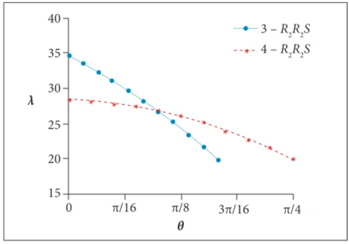
Figure 10. The relation between the deployment ratio λ and
θ for mechanisms 3- R2R2S and 4 - R2R2S.
0 π/16 3π/16 π/4
40
3 – R2R2S
4 – R
2R2S
35
30
25
20
15
θ λ
π/8
* * * * * * *
* *
* * *
REFERENCES
Cherniavsky AG, Gulyayev VI, Gaidaichuk VV, Fedoseev AI (2004). New developments in large deployable space antennae at S.P.A. EGS. Proceedings of the Engineering, Construction, and Operations in Challenging Environments, Earth and Space 2004; Houston, USA. Figure 9. The top view of the mechanism 3 - R2R2S.
r
l θ
he deployment ratio λ3 - R
2R2S is calculated as:
For the mechanism 4 - R2R2S, we set r = 300. As in the limbs the two mechanisms are the same, we set lf= 30 mm. hen we take the same process to calculate the deployment ratio as the mechanism 3 - R2R2S. he deployment ratio λ4 - R
2R2S is shown in Eq. 14:
Calculating λ on the value range of θ, we obtain the relation presented in Fig. 10.
According to Fig. 10, we conclude that, if we choose 3 - R2R2S as the unit, when θ = 0, the deployment ratio achieves its largest value; if we choose 4 - R2R2S as the unit, when θ = 0, the deployment ratio achieves its largest value. If the cylinder
A is predetermined, the mechanism 3 - R2R2S has the largest deployment ratio.
(12)
(13)
(14)
λ
3 - R 2R2Sλ
4 - R 2R2SGao F, Yang J, Ge Q (2011) Type synthesis of parallel mechanisms having the second class GF sets and two dimensional rotations. J Mech Robot 3(1):011003. doi: 10.1115/1.4002697
Huang Z, Li Q (2002) General methodology for type synthesis of symmetrical lower-mobility parallel manipulators and several novel manipulators. Int J Robot Res 21(2):131-145. doi: 10.1177/027836402760475342
Li Q, Huang Z, Hervé M (2004) Type synthesis of 3R2T 5-DOF parallel mechanisms using the Lie group of displacements. IEEE T Robotic Autom 20(2):173-180. doi: 10.1109/TRA.2004.824650
Merlet JP (2006) Parallel robots. 2nd ed. Dordrecht: Springer.
Pour ZA, Shafai L, Tabachnick B (2014) A practical approach to locate offset relector focal point and antenna misalignment using vectorial representation of far-ield radiation patterns. IEEE T Antenn Propag 62(2):991-996. doi: 10.1109/TAP.2013.2292503
Sauder JF, Thomson MW (2014). The mechanical design of a mesh Ka-band parabolic deployable antenna (KaPDA) for CubeSats. AIAA
2015-1402. Proceedings of the 2nd AIAA Spacecraft Structures Conference; Florida, USA.
Silver S (1949) Microwave antenna theory and design. New York: McGraw-Hill.
Tayebi A, Gomez J, Gonzalez I, Catedra F (2013) Inluence of the feed location on the performance of a conformed Fresnel zone relector. IEEE Antenn Wireless Propag Lett 12:547-550. doi: 10.1109/ LAWP.2013.2259460
Tsai LW (1999) Robot analysis: the mechanics of serial and parallel manipulator. New York: John Wiley & Sons.
Xu Y, Yao J, Zhao Y (2012) Type synthesis of spatial mechanisms for forging manipulators. Proc IME C J Mech Eng Sci 226(9):2320-2330. doi: 10.1177/0954406211433246