Advances in Mechanical Engineering 2016, Vol. 8(6) 1–12
ÓThe Author(s) 2016 DOI: 10.1177/1687814016652564 aime.sagepub.com
Vibration reduction in beam bridge
under moving loads using nonlinear
smooth and discontinuous oscillator
Ruilan Tian
1, Xinwei Yang
2, Qin Zhang
1and Xiuying Guo
1Abstract
The coupled system of smooth and discontinuous absorber and beam bridge under moving loads is constructed in order to detect the effectiveness of smooth and discontinuous absorber. It is worth pointing out that the coupled system con-tains an irrational restoring force which is a barrier for conventional nonlinear techniques. Hence, the harmonic balance method and Fourier expansion are used to obtain the approximate solutions of the system. The first and the second kind of generalized complete elliptic integrals are introduced. Furthermore, using power flow approach, the performance of smooth and discontinuous absorber in vibration reduction is estimated through the input energy, the dissipated energy, and the damping efficiency. It is interesting that only depending on the value of the smoothness parameter, the efficiency parameter of vibration reduction is optimized. Therefore, smooth and discontinuous absorber can adapt itself to effectively reducing the amplitude of the vibration of the beam bridge, which provides an insight to the understanding of the applications of smooth and discontinuous oscillator in engineering and power flow characteristics in nonlinear system.
Keywords
Beam bridge, nonlinear dynamic absorber, smooth and discontinuous oscillator, power flow approach, moving load
Date received: 16 February 2016; accepted: 3 May 2016
Academic Editor: Mario L Ferrari
Introduction
The vibration absorbers play an important role in vibration control in mechanical systems1–3 and com-prise a spring–damper attachment mounted on the main structure. When the main structure is forced to vibrate, the device can absorb energy to reduce its vibration amplitude. Based on the characteristics of the vibration absorber, it may be classified into two kinds: linear absorber and nonlinear one. As is well known, the effectiveness of the linear absorber is limited to the narrow frequency range. The linear absorber cannot meet the actual requirement with the development of engineering. Hence, the development of the nonlinear absorber is promoted. Riganti and Zavattaro4 consid-ered the problem of a qualitative distinction between
chaotic and hyperchaotic responses in a nonlinear vibration absorber with 2 degrees of freedom. A theore-tical study was presented to design nonlinear vibration absorbers and improve their stability and effective fre-quency bandwidths in Frank Pai and Schulz.5 Starosvetsky and Gendelman6 demonstrated that a nonlinear energy absorber can successfully absorb
1Department of Mathematics and Physics, Shijiazhuang Tiedao University, Shijiazhuang, China
2School of Traffic, Shijiazhuang Institute of Railway Technology, Shijiazhuang, China
Corresponding author:
Xinwei Yang, School of Traffic, Shijiazhuang Institute of Railway Technology, Shijiazhuang 050041, China.
Email: [email protected]
energy from both excited modes of the linear subsys-tem. The performance of nonlinear dampers was detected and two conservation laws were obtained in Samani and Pellicano.7The problem of mitigating the vibration by nonlinear dynamical absorbers was addressed.8They found that it was effective in a wide range of forcing amplitudes. Furthermore, the behavior of a new type of nonlinear dynamic vibration absorber was studied in Febbo and Machado.9 Recently, the effectiveness of the nonlinear absorber for eliminating bifurcations and suppressing the amplitude of primary resonance response was showed in Ji.10 These results mentioned above demonstrate that the nonlinear absor-bers have overcome some drawbacks of the linear absorber. But the use of nonlinear dynamic vibration absorbers (DVAs) for replacing the classical linear devices was not generally convenient in Samani and Pellicano.11 Of course, the results were related to the specific problem of moving loads and had no evidence to claim that such results could be generalized to other mechanical systems.
The investigations on vibration and control of beam bridges using the vibration absorbers have been of great significance in engineering. There are a few works on the study of vibrations of beams subjected to either sta-tionary or moving loads.12–19The structural analysis of a Timoshenko beam system with tuned mass dampers (TMDs) under moving-load excitation was presented in Chen and Chen,15 and the effectiveness of a TMD for vibrational control was emphasized. An optimal TMD system was utilized to suppress the undesirable beam vibration in Younesian et al.,16and the dynamic perfor-mance of the bridge before and after the installation of the TMD system was compared to show the effective-ness of the designed TMD system. The optimal design of a linear vibration absorber was considered for vibra-tion reducvibra-tion in simply supported beams subjected to constant moving loads in Issa Jimmy.17 The dynamic performance of a combined bridge–vehicle system with an TMD system was analyzed in Moghaddas et al.18 An optimal design of TMD system was proposed to suppress the effect of non-symmetrical and side-way motion of vehicles traveling on bridges.19Furthermore, in practice, it is worth pointing out that frequency often shifts from one mode to another in the beam bridge subjected to moving loads. All kinds of moving loads can lead to the different external excitation frequency. It involves a versatile dynamic damper which can lead itself to linear dynamic dampers or nonlinear ones to meet the demands of vibration reduction. Although the use of nonlinear absorbers overcame the drawback of narrow frequency range, the natural frequencies are fixed, which cannot adapt itself to meeting the demands of vibration reduction in order to increase load capacity and extend the service life of beam bridge. Hence, the results encourage the research on a versatile dynamic
damper which leads itself to linear dynamic damper or nonlinear one in order to meet vibration control demands.
Smooth and discontinuous (SD) oscillator was put forward by Cao et al.20,21The research results showed that the restoring force was irrational nonlinear form in the system. It was found that SD oscillator admitted codimension-two bifurcation at the trivial equilibrium in certain cases and the bifurcation diagram was drawn.22Tian et al.23investigated Hopf bifurcations of SD oscillator by introducing a series of new kinds of elliptic integrals of the first and second one. Cao and Xiong studied the complex resonant behaviors by con-structing a series of generating functions and canonical transformations to obtain the normal form of the sys-tem, which offered a better understanding of the transi-tion of resonance mechanism and further revealed the transfer mechanism of vibration energy in a nonlinear dynamical system.24Hence, SD oscillator has rich and complex dynamic behaviors, and the nature frequency can change with the smooth parameter, which indicates that it is valuable to construct SD absorber to assess its efficiency of vibration absorption.
The motivation of this article is originated from the interests in constructing SD absorber based on SD oscillator and detecting the efficiency of vibration reduction for the application of SD absorber. Hence, we propose the coupled system of SD absorber and beam bridge in this article. In order to detect the effec-tiveness of SD absorber, the coupled system of SD absorber and the beam bridge under moving loads is detected. It is noting that by introducing a series of new kinds of elliptic integrals of the first and second kind and using the harmonic balance method, we can obtain the algebraic equation whose solutions are topo-logically equivalent to the ones of the coupled system.
investigated and of particular concern is the smooth-ness parameter contributed to the characteristics of the efficiency parameter.
Mathematical model for the bridge–SD
absorber coupling system
SD oscillator is an example of a conservative nonlinear oscillatory system whose natural frequency can be changed depending on the value of the smoothness parameter.20–24In a complicated real system, frequency often shifts from one mode to another. It involves a versatile dynamic damper which can lead itself to linear dynamic dampers or nonlinear one to meet reduction demands. Hence, based on SD oscillator, SD absorber is constructed as shown in Figure 1. SD absorber con-sists of the massm2linked by a pair of inclined springs
of stiffnessk2 and a vertical damper. The oscillator can
move up and down, but cannot touch the frame. Obviously, from Figure 1, the springs of SD absorber are vertical and SD absorber can be regarded as a linear absorber (TMD). Otherwise, it can be a nonlinear one. Furthermore, its natural frequency changes depending on the values of the smoothness parametera=l0=l.
In order to detect the effectiveness of SD absorber, we assume that the beam bridge is subjected to an infi-nite series of moving loads with a constant speedv. The system model of the coupled bridge–SD absorber is shown in Figure 2. If the beam bridge is perturbed by a
viscous dampingc1, the coupled bridge–SD dynamical
system can be mathematically modeled by
EI∂
4
u ∂x4 +rA
∂2u ∂t2 +S(x)
∂2u ∂x2 +c1
∂u
∂t
= MgM∂
2
u ∂t2
d(xvt)Fd xL2
m2€yF=0
0tL
v
8
> > > > > <
> > > > > :
ð1Þ
where
F=2k2 u L2,t
y
1 l
ffiffiffiffiffiffiffiffiffiffiffiffiffiffiffiffiffiffiffiffiffiffiffiffiffiffiffiffiffiffiffiffiffiffiffiffiffi
u L
2,t
y
2
+l2 0
q 0
B @
1
C A+c2
∂u L
2,t
∂t y_
andEI,u(x,t),rA,c1,c2, andMare the flexural
rigid-ity, the vertical displacement of beam, the mass of unit length, the damping coefficient of beam, the damping coefficient of SD absorber, and the equivalent mass of moving load, respectively.S(x,t) =7EA½1=2(∂u=∂x)2is the axial force.25The use ofdfunction is to accommo-date a pointwise concentrated load. The reader can refer to Timoshenko et al.26 and Thomson and Dahleh27 for further details of the mathematical modeling.
Although more effective vibration reduction in beam bridge will be given using a heavy SD absorber, the sta-tic deflection of beam bridge increases as well. Hence, the mass of the absorber cannot be too large. Here, the mass of SD absorber is less than 1% of the total mass of the beam bridge.
We will focus our attention on efficiency of vibration reduction for SD absorber. The first mode of the beam is the dominant mode in our application and a single mode model will be adopted. Hence,ucan be written in the following form
u(x,t) =q(t) sinpx
L ð2Þ Figure 1. SD absorber.
whereq(t) is the amplitude of the mode.
Substituting equation (2) into equation (1) and inte-grating the first equation of equation (1) over (0,L), we
have
d2
q dt2 +
EIp4
rAL4q6
Ep4
8rL4q 3
+ c1 rA dq dt = 2Mg rALsin pvt L 2M rAL d2 q dt2sin
2pvt
L
2
rALð2k2(qy)
1 l
ffiffiffiffiffiffiffiffiffiffiffiffiffiffiffiffiffiffiffiffiffiffiffiffiffiffi
(qy)2
+l2 0 q 0 B @ 1 C A
+c2
dq dt dy dt m2 d2 y dt2 +c2
dq dt
dy dt
2k2(qy)
1 l
ffiffiffiffiffiffiffiffiffiffiffiffiffiffiffiffiffiffiffiffiffiffiffiffiffiffi
(qy)2+l2 0 q 0 B @ 1 C
A=0
0tL
v 8 > > > > > > > > > > > > > > > > > > > > > > > > > > > > > > > > > > > > > > > > < > > > > > > > > > > > > > > > > > > > > > > > > > > > > > > > > > > > > > > > > :
ð3Þ
Traditionally, dynamic effects on the beam bridge under the action of a single moving load are taken into account. Here, a beam bridge is subjected to an infinite series of moving loads with constant velocity which repeat at time L=v intervals. We know that
jsinpvt=Lj (t0) can substitute for
sinpvt=L (0tL=v) to discuss the vibration of
mid-span by moving loads passing through the beam bridge successively.28 Therefore, equation (3) can be written in the following form
d2
q dt2 +
EIp4
rAL4q6
Ep4
8rL4q 3
+ c1 rA
dq dt
=2Mg rAL sin pvt L 2M rAL d2 q dt2sin
2pvt
L
2
rAL 2k2(qy) 1
l
ffiffiffiffiffiffiffiffiffiffiffiffiffiffiffiffiffiffiffiffiffiffiffiffiffiffi
(qy)2+l2 0 q 0 B @ 1 C A 0 B @
+c2
dq dt dy dt m2 d2 y dt2 +c2
dq dt
dy dt
2k2(qy) 1
l
ffiffiffiffiffiffiffiffiffiffiffiffiffiffiffiffiffiffiffiffiffiffiffiffiffiffi
(qy)2+l2 0 q 0 B @ 1 C A= 0 8 > > > > > > > > > > > > > > > > > > > > > > > < > > > > > > > > > > > > > > > > > > > > > > > :
ð4Þ
Let
v21=
EIp4
rAL4,t=
t v1
,v= pv Lv1
,q=q l,y=
y l,
p=qy,a=l0
l 0,m1=
2m2
rAL,
u=
2M
rAL,f=
2Mg
lrALv2 1
,g1=
c1
rAv1
,b=6 l
2
A
8I ,
g3=
k2
m2v21
,g2=
c2
m2v1
ð5Þ
Equation (4) yields
€
q+q+bq3
+g1q_=fjsinvtj u€qsin 2
vt
m1 2g3p 1
1
ffiffiffiffiffiffiffiffiffiffiffiffiffiffiffiffi
p2
+a2
p
!
+g2p_
!
€
p+2g3p 1 1 ffiffiffiffiffiffiffiffiffiffiffiffiffiffiffiffi
p2
+a2
p
!
+g2p_=€q
8 > > > > > > > < > > > > > > > :
ð6Þ
Clearly, from equation (4), the limit case of SD absorber, that is, a=0, can be regarded as TMD.
Furthermore, it is interesting that the natural frequency of SD absorber can be changed depended on the value of the smoothness parameter. Hence, SD absorber can be the linear absorber (TMD) or nonlinear one, which can adapt itself to meeting vibration reduction demands and broaden its applications in engineering.
Solution procedure and dynamical analysis
Power flow theory has been one of the major methods for studying vibration.29–33 Vibratory power flow can be introduced to examine the efficiency of SD absorber, which contains the force, the speed, and their phase relationship and can describe power flow transmissions more accurately in dynamical system. It is necessary to study the performance of SD absorber in vibration reduction using power flow approach. Hence, we focus our attention on the solution of equation (6) in this sec-tion. By introducing a series of new kinds of elliptic integrals of the first and second kind and using the har-monic balance method,26we obtain the algebraic equa-tion whose soluequa-tions are topologically equivalent to the ones of the original equation (6).
Obviously, the external excitation fjsinvtj can be expanded into a Fourier series up to the first order
fjsinvtj=2f
p
4f
3pcos2vt+ ð7Þ
Let
q=q0+q1 cos2vt+q2 sin2vt
p=p1cos (2vt+f)
2vt+f=u
8
> <
> :
and the nonlinear restoring force 2g3p(11= ffiffiffiffiffiffiffiffiffiffiffiffiffiffiffiffi
p2
+a2
p
) +g2p_is represented as Fourier expansions
up to the first order
2g3p 1 ffiffiffiffiffiffiffiffiffiffiffiffi1
p2
+a2
p
+g2p_
=R0+R1 cosu+R2 sinu+
ð9Þ
where
R0=
1
2p ð p
p
2g3p 1 1
ffiffiffiffiffiffiffiffiffiffiffiffiffiffiffiffi
p2
+a2
p
!
+g2p_
!
du
R1=
1
p
ðp
p
2g3p 1 1
ffiffiffiffiffiffiffiffiffiffiffiffiffiffiffiffi
p2
+a2
p
!
+g2p_
!
cosudu
R2=
1
p
ðp
p
2g3p 1 1
ffiffiffiffiffiffiffiffiffiffiffiffiffiffiffiffi
p2
+a2
p
!
+g2p_
!
sinudu
ð10Þ
Of course, when equations (7) and (9) are used each time, the leading order terms are used.
Clearly
R0=0 ð11Þ
R2= 2g2vp1 ð12Þ
To calculate R1 in equation (10), we introduce the
generalized complete elliptic integrals of the first and the second kind as follows18
SDK½k= EllipticK½k, j jk
\1
lim k
j j!1 1
ffiffiffiffiffiffiffiffi
1k2
p =‘, j jk =1 (
ð13Þ
and
SDE½k= EllipticE½k, j jk
\1
lim k
j j!1EllipticE½k=
1, j jk =1 (
ð14Þ
where EllipticK½k and EllipticE½k represent the com-plete elliptic integrals of the first and the second kind, respectively.
Therefore
R1=2g3p1+
8g3a2
pp1
ffiffiffiffiffiffiffiffiffiffiffiffiffiffiffiffi
p2 1+a
2 p SDK ffiffiffiffiffiffiffiffiffiffiffiffiffiffiffiffi p2 1 p2 1+a
2
s !
8g3
ffiffiffiffiffiffiffiffiffiffiffiffiffiffiffiffi
p2 1+a
2 p pp1 SDE ffiffiffiffiffiffiffiffiffiffiffiffiffiffiffiffi p2 1 p2 1+a
2
s ! ð15Þ
In the special case ofa=0, that is
lim
a!0
8g3a2
pp1
ffiffiffiffiffiffiffiffiffiffiffiffiffiffiffiffi
p2 1+a
2 p SDK ffiffiffiffiffiffiffiffiffiffiffiffiffiffiffiffi p2 1 p2 1+a
2
s !
= lim
a!0
8g3a2
pp1
ffiffiffiffiffiffiffiffiffiffiffiffiffiffiffiffi
p2 1+a
2
p
1
ffiffiffiffiffiffiffiffiffiffiffiffiffiffiffiffiffiffiffiffi
1 p
2 1 p2
1+a 2
r =0
lim
a!0
8g3 ffiffiffiffiffiffiffiffiffiffiffiffiffiffiffiffip2 1+a
2 p pp1 SDE ffiffiffiffiffiffiffiffiffiffiffiffiffiffiffiffi p2 1 p2 1+a
2
s !
=8g3 p
ð16Þ
we have
R1=2g3p1
8g3
p
= lim
a!0
2g3p1+
8g3a2
pp1
ffiffiffiffiffiffiffiffiffiffiffiffiffiffiffiffi
p2 1+a
2 p SDK ffiffiffiffiffiffiffiffiffiffiffiffiffiffiffiffi p2 1 p2 1+a
2
s !
" #
lim
a!0
8g3 ffiffiffiffiffiffiffiffiffiffiffiffiffiffiffiffip2 1+a
2 p pp1 SDE ffiffiffiffiffiffiffiffiffiffiffiffiffiffiffiffi p2 1 p2 1+a
2
s !
" #
ð17Þ
Hence, we have successfully introduced generalized complete elliptic integrals of the first and second kind in investigating the Fourier expansions of the irrational nonlinear restoring force for both smooth, that is,a.0
and discontinuous stages, that is,a=0.
The general idea of the harmonic balance method is to represent each time history by its frequency content to obtain a series of algebraic equations by balancing the same frequency components. Hence, substituting equations (7)–(9) into equation (6) and comparing the coefficients of the same harmonics (i.e. sin2vt,
cos2vt), we obtain
q0+b q 3 0+
3
2q0q
2 1+
3
2q0q
2 2
+v2uq1
2f
p =0
3bq20q1+
3
4bq
3 1+
3
4bq1q
2
2+ (14v 2
2v2u)q1
+2g1vq2+m1(R1 cosf+R2 sinf) + 4f
3p=
0
3bq20q2+
3 4bq 3 2+ 3 4bq 2
1q2+ (14v 2
2v2u)q2
2g1vq1+m1(R2 cosfR1 sinf) =0
4v2p1 cosfR1 cosfR2 sinf4v 2
q1=0
4v2p1 sinf+R2 cosfR1 sinf+4v 2
q2=0
8 > > > > > > > > > > > > > > > > > > > < > > > > > > > > > > > > > > > > > > > :
ð18Þ
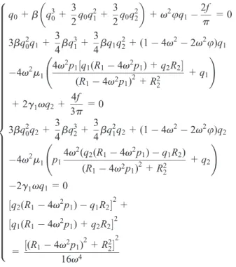
q0+b q 3 0+
3
2q0q
2 1+
3
2q0q
2 2
+v2uq1
2f
p =0
3bq20q1+3 4bq
3 1+
3
4bq1q
2
2+ (14v 2
2v2u)q1
4v2m1 4v2
p1½q1(R14v 2
p1) +q2R2
(R14v2p1) 2
+R2 2
+q1
!
+2g1vq2+
4f
3p =0
3bq2
0q2+
3 4bq 3 2+ 3 4bq 2
1q2+ (14v 2
2v2u)q2
4v2m1 p1
4v2(q2(R14v 2
p1)q1R2)
(R14v2p1) 2
+R2 2
+q2
!
2g1vq1=0 ½q2(R14v
2
p1)q1R2 2
+
½q1(R14v 2
p1) +q2R2 2
=½(R14v
2
p1) 2
+R2 2
2
16v4
8 > > > > > > > > > > > > > > > > > > > > > > > > > > > > > > > > > > > > < > > > > > > > > > > > > > > > > > > > > > > > > > > > > > > > > > > > > :
ð19Þ
The numerical method is used to obtain the solutions of equations (6) and (19), that is, the original equation and the algebraic equation, in order to demonstrate the validity of the harmonic balance method. Three different speeds are examined, and other parameters are EI= 3:099631010N m2, r=7000kg=m3, A=6:8m2,
c1=0:02N=(m=s), L=40m, m2=3000kg, c2=
0:01N=(m=s), k2=500N=m, M=5000kg, and
l=10 m. Figure 3(a) displays the maximum of the
amplitude for the middle span of the bridge, that is, Max=q0+
ffiffiffiffiffiffiffiffiffiffiffiffiffiffiffiffiffiffiffi
q12+q22
p
for equation (19) andqmax for equation (6). Figure 3(b) representsp1andpmax for SD
absorber in equations (19) and (6).
The effect of v on the vibration of the coupled bridge–SD dynamical system and the validity of the harmonic balance method are examined as follows:
1. The values of Max and p1 are similar to qmax
and pmax in different speeds for the system, as shown in equations (6) and (19) (see Figure 3), respectively. Hence, the harmonic balance method is effective.
2. As a increases, Max decreases in Figure 3(a), while p1 increases in Figure 3(b). Furthermore,
it is noting that whena is up to a given value, the vibration reduction efficiency changes little, which reveals that the effective vibration absorp-tion of SD absorber is relatively steady depend-ing on the parametera6¼0.
Once the nonlinear dynamic displacements can be obtained using the harmonic balance method, the asso-ciated vibratory power flow will be calculated from the inner product of the force and the corresponding velo-city response in this section. Furthermore, the portion of the input energy dissipated by the viscous damper and the kinetic energy of SD absorber is computed, which shows the effect of SD absorber.
Input power flow
Let
u=u
l ð20Þ
From x=vt, equation (3), and the transformation (5), we have
u=qsinvt ð21Þ
Substituting the first equation of the transformation (8) into equation (21), the first derivation of u with respect totyields
_
u=1
2v
ffiffiffiffiffiffiffiffiffiffiffiffiffiffiffiffiffiffiffiffiffiffiffiffiffiffiffiffiffiffiffiffiffi
(2q0q1) 2
+q2 2
q
cos (vt+u2)
+3
ffiffiffiffiffiffiffiffiffiffiffiffiffiffiffiffi
q2 1+q
2 2
q
cos (3vtu1)
ð22Þ
whereu1= arctan q2=q1andu2= arctanq2=2q0q1.
The instantaneous input power flow density pin at any point x=vt is defined by the dot product of the velocity and the force F= (fjsin (vt)j u€qsin2vt) caused by moving loads and the axial force, that is
pin=Fu_ ð23Þ
Hence, the time-averaged input power flowPinis
Pin=v p
ð
p v
0
pindt
=8uv
3
15p
ffiffiffiffiffiffiffiffiffiffiffiffiffiffiffiffiffiffiffi
q12+q22
p ffiffiffiffiffiffiffiffiffiffiffiffiffiffiffiffiffiffiffiffiffiffiffiffiffiffiffiffiffiffiffiffiffiffiffi
(2q0q1) 2
+q22
q
(2cosu2 sinu1+3cosu1 sinu2)
fv
4
ffiffiffiffiffiffiffiffiffiffiffiffiffiffiffiffiffiffiffiffiffiffiffiffiffiffiffiffiffiffiffiffiffiffiffi
(2q0q1) 2
+q22
q
sinu2
4uv
3
35p (q1
2
+q2 2
) sin2u1
ð24Þ
From equation (24),Pin is associated withf,v, and u, that is, the quality and velocity of moving loads. However, the specific relationship is not clear. Based on such reasons, we will study the absorption power flow and the damping efficiency in the following section.
Absorption power flow
The instantaneous and time-averaged absorption power flow absorbed by SD absorber can be derived. That is, the instantaneous absorption power flow pa and the time-averaged absorption power flowPa absorbed by SD absorber are given, respectively, by
pa= 2g3p 1 1 ffiffiffiffiffiffiffiffiffiffiffiffiffiffiffiffi
p2
+a2
p
!
+g2p_
!
_
p ð25Þ
and
Pa= v p
ð
p v
0
padt ð26Þ
Substituting the second equation of the transforma-tion (8) and (25) into equatransforma-tion (26) yields
Pa=2vp1
2 ffiffiffiffiffiffiffiffiffiffiffiffiffiffiffiffiffiffiffiffiffiffiffiffiffi
g3 2
+g2 2
v2
p
sinj ð27Þ
wherej= arctang2v=g3.
Especially, when k2=0, the time-averaged
dissi-pated powerPd flow satisfies
Pd=2g2v 2
p1 2
ð28Þ
Obviously,Pd is associated withg2,v, andp1, that
is, the characters of SD oscillator. In that case, we will aim at optimizing SD absorber to achieve an ideal effect of vibration reduction.
Efficiency of SD absorber
The aim of the power flow control is to increase absorp-tion power flow and reduce the input power flow as much as possible. We introduced h as the efficiency parameter of vibration reduction which is the ratio of PinandPd, that is
h= Pd
Pin ð29Þ
Hence, whenhis close to 1, the input power is con-verted into the dissipative energy as much as possible to minimize the vibration of the bridge, which is an ideal situation. Furthermore, it is interesting that the natural frequency of SD absorber can be changed depending on the value of the smoothness parametera. SD absor-ber is just the linear absorabsor-ber (TMD), that is,a=0, or
the nonlinear absorber, that is,a6¼0. Therefore, in this
section, the influences of different parameters onhare investigated and of particular concern is the parameter acontributed to the character ofh.
Effects of the mass of moving load and the
smoothness parameter
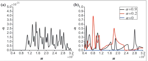
To examine the effect of the equivalent mass of the moving loadMonh, three different values of the para-meter a, that is, a=0,0:2, and0:9 are examined in
Mh plane (see Figure 3). The other parameters are chosen as EI=3:099631010
N m2
, r=7000kg=m3,
A=6:8m2, c1=0:02N=(m=s), L=40m,
m2=3000kg, c2=0:00001N=(m=s), k2=500N=m,
l=10 m, and v=18m=s. The results presented in
Figure 4 reveal that the equivalent mass of moving load M and the smoothness parameter a have significant influences on the character ofh. The following charac-teristics ofhare observed:
1. The values ofhare very near to 0 fora=0(see
Figure 4(a)), while the values of the efficiency parameter of vibration reduction, that is,h, can reach a value between0:1and 0:8 fora6¼0(see
Figure 4(b)). These results reveal that the SD-nonlinear absorber, that is,a6¼0, possesses
bet-ter effects of vibration reduction with respect to the SD-linear absorber, that is,a=0.
respectively (see Figure 4). Hence, SD absorber can adapt itself to obtaining the better effect of vibration reduction.
3. As the parameter a increases, the values of h are irregular (see Figure 4(b)). When the equiva-lent mass of moving load M yields
79,600kgM90,000kg and 170,000kg
M230,000kg, there is no better advantage in
using the SD-nonlinear absorber for a=0:9
than the SD-nonlinear absorber for a=0:2.
But, as the equivalent mass of moving loadM satisfies 48,500kgM52,000kg and 230,000kgM290,000kg, the advantage of
the former in reducing the maximum amplitude of vibration is more significant than one of the latter. Therefore, fundamental studies are still needed to reveal the basic principles governing the characteristics ofh depending on the para-metera.
Effects of the mass ratio and the smoothness
parameter
The effects of the mass ratiom=m2=rALonhare now
examined with three different values of the parameter a, that is, a=0,0:32, and0:7, and other parameters
fixed as EI= 3:099631010
N m2, r=5500kg=m3,
A=6:8m2, c1=0:02N=(m=s), L=40m,
c2=0:0001N=(m=s), k2=500N=m, M=50,000kg,
l=10 m, and v=32:1m=s. Figure 5(a) displays that
the mass ratiomhas no obvious influence onh, whileh lies in an approximate straight line in Figure 5(b) for a=0. Furthermore, the SD-nonlinear absorber (red
line) behaves better than the SD-linear absorber (blue line) for0\m\0:0038. But, when the mass ratio yields m!0:0038, this advantage will gradually disappear.
Hence, in order to achieve the better effects of vibra-tion absorpvibra-tion, the values of the parameteraare con-structed. For 0\m\0:0023, we can take a=0:32. Figure 4. Influence ofMandaonh: (a)a=0 and (b)a=0,0:2, and 0:9.
Especially, when m=0:0019, h is beyond 90%. For 0:0023\m\0:0047, we can choose a=0:7, while m.0:0047,a=0:7, anda=0 are considered. These
results reveal the flexibility of SD absorber, which can adapt itself to meeting vibration reduction demands.
Performance of the frequency-variable absorber
Previous research has clearly shown that a better under-standing of the parameteracontributed to the charac-ter ofhis very necessary. Therefore, we will detect the above problem in detail.The efficiency parameter of vibration reduction, that is, h, for the equivalent mass of moving load M, the mass ratiom, and the speed of moving loadvis calcu-lated in the parameter a domain. The parameters are fixed as EI= 3:099631010
N m2, r=5500kg=m3,
A=6:8m2, c1=0:02N=(m=s), L=40m,
c2=0:0001N=(m=s),k2=500N=m, andl=10 m.
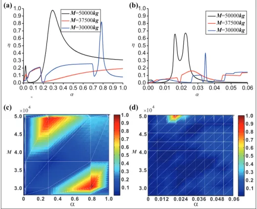
Figure 6 illustrates the effect ofaand Monhand the other parameters choose v= 32:1 m=s, m2=
3000kg. Clearly, when M=30,000,37,500, and 50,000kg, the values of h can reach the biggest by
adjusting the value of a, respectively, which show the advantages of the frequency conversion. In addition, the damping effect is poor fora=0, while it is
signifi-cant fora6¼0. That is, more than 90% of the input
power flow is absorbed by the nonlinear absorber. Figure 6(b) presents the details near a=0 in
Figure 6(a). When a=0:022, we can see that the
damping effect is also significant for M=50,000kg.
Therefore, there are two main peaks of h for M=50,000kg. Clearly, the scope ofa for the second
state is wide (see Figure 6(c) and (d)). Therefore, the latter should be chosen in the practical application.
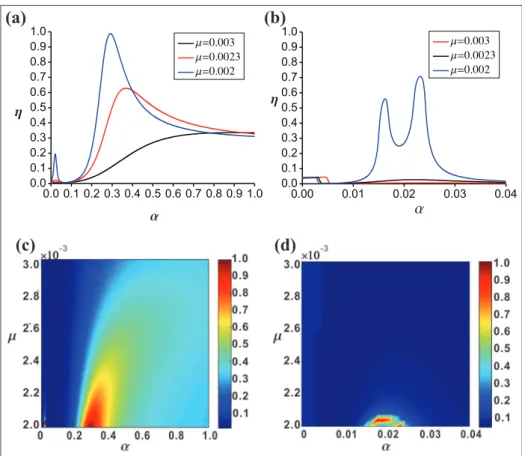
In order to reveal the effects ofaonhfor the differ-ent mass ratios, the parameters M=50,000kg,
v=32:1m=s are set in Figure 7. Figure 7(a) examines
the characteristics of the parameter h by varying the mass ratios m=0:003,0:0023, and0:002. Figure 6(b)
shows the details of the structure for 0a0:04 in
Figure 7(a). It is seen that the effect of vibration reduc-tion will rise as the mass ratio increases when the value ofais near to 0, that is, the linear absorber (see Figure 7(b)). But when the value ofais not equal to 0, that is, the nonlinear one, the parameterhdoes not follow the same rule (see Figure 7(a) and (b)). There are some peaks forhwhich corresponds tom, which reveals that SD absorber can adapt itself to meeting the requirement of vibration reduction. Furthermore, from Figure 7(c) and (d), we can see that the damping effect is also sig-nificant for0:00201m0:00204when0:01a0:03
and0:2a0:4. Figure 7(d) confirms thathfloats up
and down seriously asaranges between0:01and0:03,
which reveals that the former should not be chosen in the practical application.
Figure 8 shows that the relationship between aand h which varies with the speed of the moving load. The parametersM=50,000kg, m2=3000kg are
consid-ered, and the moving speeds are v=33:91,32:10, and 30m=s. It can be seen that for the special range of the
moving speed, SD absorber can effectively reduce the amplitude of the vibration of the beam bridge, that is, the value ofhis up to0:8, which indicates the necessity
for the speed limit.
To sum up, the natural frequency of SD absorber can be changed depending on the value of the smooth-ness parameter. Hence, SD absorber can be the linear absorber (TMD) or the nonlinear one, which can adapt itself to meeting vibration reduction demands. Rather, from Figures 4, 6, and 8, we know that the results seem random. In fact, these illusions originate from the defi-nition of h(see equations (24), (28), and (29)). In par-ticular, Pin is associated with trigonometric functions. Hence, they are non-random.
Figure 7. Influence ofaandmonh: (a)m=0:002,0:0023, and 0:003; (b) details of (a) for 0<a<0:04; (c) pseudo color plot of (a); and (d) pseudo color plot of (b).
Conclusion
SD absorber was proposed to suppress the vibrations of the beam bridge under successive moving loads which repeat at timeL=vintervals. The research was focused on the analysis of the effectiveness of SD absorber, and the efficiency parameter of vibration reductionh, that is, the ratio ofPinandPd, was introduced. The influence of different parameters on h was investigated and of particular concern was the parameterawhich contribu-ted to the characteristics of h. Only depending on the value of the smoothness parameter a, the efficiency parameter of vibration reduction was optimized. That is, SD absorber can adapt itself to meeting the demands of vibration reduction to increase load capacity and extend the service life of beam bridge.
It is worth pointing out that frequency often shifts from one mode to another in a complicated real beam bridge, which involves a versatile dynamic damper which can lead itself to linear dynamic dampers or non-linear one to meet reduction demands. SD absorber is just the linear absorber or the nonlinear absorber and its natural frequency changes depending on the value of the smoothness parametera, which has laid a theoreti-cal foundation for the design of a variable-frequency absorber.
Declaration of conflicting interests
The author(s) declared no potential conflicts of interest with respect to the research, authorship, and/or publication of this article.
Funding
The author(s) disclosed receipt of the following financial sup-port for the research, authorship, and/or publication of this article: This work was supported by the Natural Science Foundation of China (nos 11372196, 11472180, and 11302136), Natural Science Foundation for Breeding Outstanding Young Researcher in Hebei Province of China (no. A2015210097), Natural Science Youth Foundation in Hebei Province of China (no. A2015421006), the New Century Talent Foundation of Ministry of Education (NCET-13-0913), and the Training Program for Leading Talent in University Innovative Research Team in Hebei Province (no. LJRC006).
References
1. Stancioiu D, Ouyang HJ and Mottershead JE. Vibration of a continuous beam with multiple elastic supports excited by a moving two-axle system with separation. Meccanica2009; 44: 293–303.
2. Yang SP, Chen LQ and Li SH.Dynamics of vehicle-road coupled system. New York: Springer jointly published with Science Press, 2015.
3. Yang SP, Li SH and Lu YJ. Investigation on dynamical interaction between a heavy vehicle and road pavement. Vehicle Syst Dyn2010; 48: 923–944.
4. Riganti R and Zavattaro MG. Transition to hyperchaos in the dynamics of a nonlinear vibration absorber.Math Comput Model1995; 22: 55–61.
5. Frank Pai P and Schulz MJ. Refined nonlinear vibration absorber.Int J Mech Sci2000; 42: 537–560.
6. Starosvetsky Y and Gendelman OV. Dynamics of a strongly nonlinear vibration absorber coupled to a har-monically excited two-degree-of-freedom system.J Sound Vib2008; 312: 234–256.
7. Samani FS and Pellicano F. Vibration reduction on beams subjected to moving loads using linear and non-linear dynamic absorbers. J Sound Vib 2009; 325: 742–754.
8. Viguie´ R and Kerschen G. Nonlinear vibration absorber coupled to a nonlinear primary system: a tuning metho-dology.J Sound Vib2009; 326: 780–793.
9. Febbo M and Machado SP. Nonlinear dynamic vibra-tion absorbers with a saturavibra-tion.J Sound Vib2013; 332: 1465–1483.
10. Ji JC. Design of a nonlinear vibration absorber using three-to-one internal resonances. Mech Syst Signal Pr 2014; 42: 236–246.
11. Samani FS and Pellicano F. Vibration reduction of beams under successive traveling loads by means of linear and nonlinear dynamic absorbers. J Sound Vib 2012; 331: 2272–2290.
12. Yang XW, Tian RL and Li HT. Codimension-two bifur-cation of axial loaded beam bridge subjected to an infinite series of moving loads.Chin Phys B2013; 22: 120502. 13. Ding H, Yang Y, Chen LQ, et al. Vibration of
vehicle-pavement coupled system based on a Timoshenko beam on a nonlinear foundation. J Sound Vib 2014; 333: 6623–6636.
14. Ding H, Shi KL, Chen LQ, et al. Adomian polynomials for nonlinear response of supported Timoshenko beams subjected to a moving harmonic load.Acta Mech Solida Sin2014; 27: 383–393.
15. Chen YH and Chen DS. Timoshenko beam with tuned mass dampers to moving loads. J Bridge Eng 2004; 9: 167–177.
16. Younesian D, Kargarnovin MH and Esmailzadeh E. Optimal passive vibration control of Timoshenko beams with arbitrary boundary conditions traversed by moving loads. Proc IMechE, Part K: J Multi-body Dynamics 2008; 222: 179–188.
17. Issa Jimmy S. Vibration absorbers for simply supported beams subjected to constant moving loads.Proc IMechE, Part K: J Multi-body Dynamics2012; 226: 398–404. 18. Moghaddas M, Esmailzadeh E, Sedaghati R, et al.
Vibra-tion control of Timoshenko beam traversed by moving vehicle using optimized tuned mass damper.J Vib Con-trol2012; 18: 757–773.
19. Rostam MR, Javid F, Esmailzadeh E, et al. Vibration suppression of curved beams traversed by off-center mov-ing loads.J Sound Vib2015; 352: 1–15.
20. Cao QJ, Wiercigroch M, Pavlovskaia EE, et al. Archety-pal oscillator for smooth and discontinuous dynamics. Phys Rev E2006; 74: 046218.
and discontinuous dynamics.Philos T R Soc A2008; 366: 635–652.
22. Tian RL, Cao QJ and Yang SP. The codimension-two bifurcation for the recent proposed SD oscillator. Non-linear Dynam2010; 59: 19–27.
23. Tian RL, Cao QJ and Li ZX. Hopf bifurcations for the recently proposed smooth-and-discontinuous oscillator. Chinese Phys Lett2010; 27: 074701.
24. Cao QJ, Xiong YP and Wiercigroch M. Resonances of the SD oscillator due to the discontinuous phase.J Appl Anal Comput2011; 1: 183–191.
25. Kim SM. Vibration and stability of axial loaded beams on elastic foundation under moving harmonic loads.Eng Struct2004; 26: 95–105.
26. Timoshenko S, Young SH and Weaver W. Vibration problems in engineering. 4th ed. Hoboken, NJ: John Wiley & Sons, 1974.
27. Thomson WT and Dahleh MD.Theory of vibration with applications. 5th ed. Upper Saddle, NJ: Prentice Hall, 1997.
28. Tian RL, Yang XW, Cao QJ, et al. The study on the mid-span deflection of a beam bridge under moving loads based on SD oscillator. Int J Bifurcat Chaos 2012; 22: 1250108.
29. Xiong YP, Xing JT and Price WG. Interactive power flow characteristics of an integrated equipment-nonlinear isolator-travelling flexible ship excited by sea waves. J Sound Vib2005; 287: 245–276.
30. Choi WJ, Xiong YP and Shenoi RA. Power flow analysis for a floating sandwich raft isolation system using a higher-order theory.J Sound Vib2009; 319: 228–246. 31. Yang J, Xiong YP and Xing JT. Dynamics and power
flow behaviour of a nonlinear vibration isolation system with a negative stiffness mechanism. J Sound Vib2013; 332: 167–183.
32. Wang D, Chen YS, Cao QJ, et al. Dynamic analysis of a 2-DOF turbomachine blade with coupling of bending and torsion.J Vib Shock2014; 33: 199–205.