Abstract— This paper presents a multiple input multiple output (MIMO) antenna for multiband operation based on meander lines with L shaped metallic strip. Meander lines is basically a monopole antenna loaded with multiple sections of short circuited transmission line that acts as inductor and alter the impedance characteristics of antenna. Antenna size miniaturization of 69 % has been achieved by placing double U slots on the ground plane and a line slot DGS (Defective Ground Structure) is used to reduce the mutual coupling between the antenna elements. The values of envelope correlation coefficient (ECC) and Specific Absorption Rate (SAR) lie well below the specified limit.
Index Terms— MIMO, mobile antenna, multiband antenna, wireless communications, high isolation, miniaturization.
I. INTRODUCTION
With the increasing functionality, the modern mobile handsets are required to operate for a number
of applications including real time voice communication, text message service, Wi-Fi, Bluetooth,
global positioning system (GPS) and video applications, etc. All these applications require different
frequency bands for their operation, which calls for requirement of multiband antennas [1-4].
Moreover, the wireless communication system is plagued with multiple limitations like fading, lower
channel capacity, lower bit rate etc. These limitations are needed to be addressed while designing
antennas for wireless communication systems.
Multiple-input multiple-output (MIMO) technology has been considered as a basic need for
emerging and future wireless communication standards including IEEE 802.11n (Wi-Fi), IEEE
802.11ac (Wi-Fi), HSPA+ (3G), WiMAX (4G), and Long term Evolution (4G) [5]. MIMO
technology basically enhances the performance of wireless communication systems by improving the
transmission speed, channel capacity and bit rate. MIMO utilizes multipath propagation by employing
multiple antennas for transmission and reception [6]. However, the availability of limited space on
handset circuitry makes it difficult to integrate two or more antennas in a mobile device. This problem
can be overcome by placing compact antennas very close to each other in the limited available space.
When antennas are placed very close, electromagnetic interactions between the elements lead to large
mutual coupling which results in impedance mismatch, reduced radiation efficiency and increased
Compact εIεO Antenna for εultiband
εobile Applications
Tanvi Agrawal, Shweta Srivastava,Electronics and Communication Engineering Department, Jaypee Institute of Information and Technology, Sector 62, India,
antenna correlation coefficient [7]. This degrades the performance of MIMO systems. Therefore, it is
a challenging task to design MIMO antenna with small size while obtaining high isolation.
There are different techniques for increasing the isolation between the antenna elements of MIMO
that includes: use of decoupling and matching networks [8-9], electromagnetic band-gap structures
(EBG) [10], neutralizing lines [11], parasitic elements (PE) [12] and split ring resonators [13], slots
used in the ground planes [14]. All these methods can enhance the isolation between the antenna
elements by -15 dB or less. But, application of these techniques in the MIMO antenna requires a large
area and also complicates the structures. Therefore, these techniques cannot be suitably used in
mobile handset applications. Some other techniques like T-shaped slot etched on ground plane and
parasitic meander line [15-16] are effective techniques for enhancing isolation in mobile devices.
Various types of printed antennas have been proposed for MIMO applications in recent years [17].
Out of these structures, meander line antenna has been widely used in design of these systems because
of its low profile and simple structure [18]. Meander line antennas are very small in size and can
operate at multiple frequency bands hence they are suitable for MIMO applications. These antennas
also have some limitations such as low radiation efficiency and low bandwidth.
The proposed research presents a multiband, two element MIMO antenna based on a meander line
with L shaped strip. A high degree of miniaturization has been achieved by placing double U slot
under the antenna elements on the ground plane. These U slots change the overall current distribution
on the ground plane resulting in the current following a longer path that shifts the lowest operating
frequency to 1.8 GHz from 5.7 GHz. A high degree of isolation up to -57 dB has been achieved at 1.8
GHz by a line slot DGS that prevents the surface waves to propagate between the antenna elements.
DGS etched on ground plane also have lesser effect on original antenna impedance as compared to the
traditional isolation techniques.
II. ANTENNA CONFIGURATION
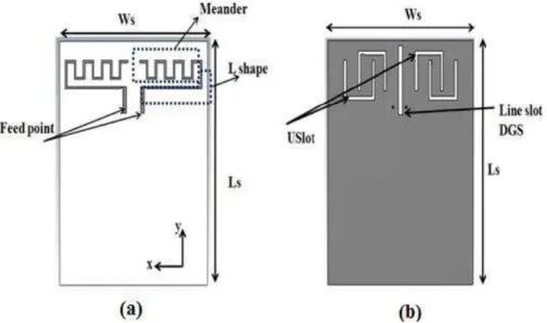
The configuration of the proposed multiband MIMO antenna is given in Fig. 1. It is printed on a
102 mm × 80 mm FR4 substrate having thickness of 1.6 mm, relative dielectric constant of 4.4 and a
loss tangent of 0.02. The top layer consists of two closely spaced antenna elements with microstrip
feed lines. Bottom layer is a metallic ground with two double U slots and a line slot as DGS. The
antenna elements are meander line antenna with L shaped strip which are placed symmetrically. Two
U slots have been etched out in the ground plane to improve the impedance matching characteristic
that provides multiband operation. Line slot reduces the mutual coupling between antenna elements.
The proposed antenna has been presented with an extended ground plane to accommodate the
Fig. 1.Configuration of proposed MIMO antenna (a) front view (b) back view
A. Antenna Element Design
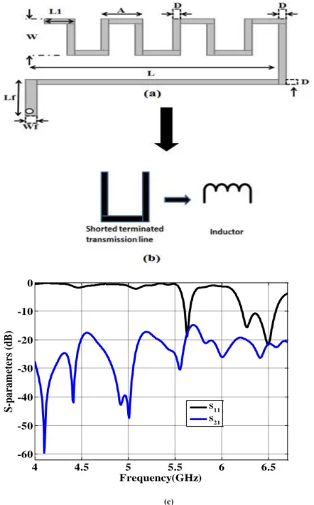
The geometry of proposed meander line antenna has been shown in Fig. 2(a). The antenna has a
size of L1 ×W with d as the line width photo-lithographed on the substrate of dielectric constant of
4.4 and thickness 1.6mm. A microstrip line of length Lf and width wf is used to feed electrical signals
to the meander. Each meander line section acts as a load, and they can be considered as transmission
lines with shorted terminals as shown in Fig. 2(b). Each section of the meander can be equated to an
electrical inductor. The inductance value in the equivalent circuit as shown in Fig. 2(a) can be
evaluated using the geometrical parameters: spacing between the loops of the meander line sections
(p), width (w), and line width (d). The impedance of the complete meander line section on a substrate
can be calculated using the following relation [19]:
���= � tan � (1)
where, k = k √ r, k is the wave number in free space. The corresponding electrical inductance Lin
of each meander section is given in (2), where ω is the operating frequency
Lin=
WZ tan kw (2)
The numbers of loops of the meander line are denoted by N. The total electrical inductance of the
meander line antenna is given as N × Lin. Current distribution on the meander line along with the
ground plane determines the radiation pattern of the antenna. The current along the x -axis in the
meander effectively contributes to the incoming field in the E-plane; on the other hand the current
distribution along the y-axis will give outgoing field in the E-plane. Hence, the current distribution
along the x- axis will determine the radiation field of a meander line antenna [19].
The commercial Ansys HFSS software is used to design and simulate the antenna. The parameters
of the antenna are L=31 mm, w= 8 mm, p=4 mm, d=1mm, l1= 3.75 mm, Lf=10 mm and wf=2 mm.
that the antenna resonates at 5.7 and 6.5 GHz with S11 value of -19 dB and -21 dB respectively.
Mutual coupling (S21) is also -19 dB and -21 dB respectively at these frequencies.
(c)
Fig .2 (a) Meander configuration (b) its inductor equivalent circuit and (c) S-parameters of proposed MIMO antenna.
B. Double U Slot
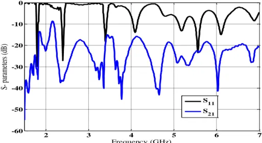
The impedance matching characteristic at low frequencies can be improved by etching two double
U-slots of length Lu= 8 mm and width Wu = 1.5 mm on the ground plane under both the antenna
elements as shown in Fig. 1(b). The simulated S-parameters of this antenna with modified ground
structure are shown in Fig. 3. As observed, slots shift the first resonant frequency of the antenna from
5.7 GHz to 1.8 GHz. Also the antenna now resonates at seven different frequencies providing
coverage to most of the wireless bands. The shifting in frequency is due to the excitation of double U
slot etched on the ground plane by the field of the antenna as shown in Fig.4. The double U slots
4 4.5 5 5.5 6 6.5
-60 -50 -40 -30 -20 -10 0
Frequency(GHz)
S-pa
ra
m
eters
(dB)
S11
change the current distribution and extend the current path adequately. The higher is the extended
path of the slots; the lesser will be the first resonant frequency. For the given dimensions and
geometry it is evident that this antenna(see Fig. 3(c)) is operating at 1.8 GHz, 2.4 GHz, 3.4 GHz,
4.18 GHz, 5.2 GHz, 5.5 GHz and 6.1 GHz.
Fig. 3- S-parameters of proposed MIMO antenna with double U slot
Fig.4. Current Distribution (excited port 2) at 1.8 GHz without Line Slot (a) Front view (b) Back View
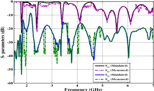
C. Line Slot
Since the common ground plane has been used by both the antenna elements, it may increase
mutual coupling and reduce isolation. The common ground plane for such small antennas acts as a
part of their radiating element that leads to the flow of surface waves. These surface waves couple the
field to the adjacent elements and increase the correlation between different elements of antenna (see
fig.4). A line slot of length Lg = 29mm and width Wg= 2mm has been etched out on the ground plane
to prevent these surface waves reaching the other antenna element to achieve batter isolation (see Fig.
6(b)). The results obtained from the simulation of this antenna are shown in Fig. 5 (continuous line)
2 3 4 5 6 7
-60 -50 -40 -30 -20 -10 0
Frequency (GHz)
pa
ra
m
et
er
s
(dB
)
S11
that shows a significant reduction in mutual coupling as compared to the results in Fig. 3, which has
low reflection coefficient and isolation at 1.8 GHz. Furthermore, the impedance matching
characteristics in the other frequency bands has also improved.
Fig. 5. Simulated and measured S-parameters of proposed MIMO antenna with double U slots and Line slot
Fig.6. Current Distribution (excited port 2) at 1.8 GHz with Line Slot (a) Front view (b) Back View
III. RESULTS AND DISCUSSION
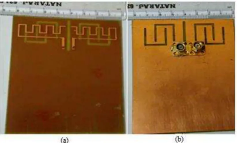
Fig.7 shows the fabricated prototype of the proposed antenna. A Vector Network Analyser has been
used for measurement and verification of the antenna performance. The return loss of the antenna was
measured by exciting one of the ports of the antenna, whereas the other was terminated with a 50Ω
load. It is evident from the graph (see Fig. 5) that both simulated and experimental results are in good
agreement.
2 3 4 5 6 7
-60 -50 -40 -30 -20 -10 0
Frequency (GHz)
p
ar
am
et
er
s
(d
B
)
Fig.7. Fabricated prototype of the proposed antenna (a) Front View (b) Back View
A. Radiation Performance
The radiation characteristics of the proposed antenna at its operating frequencies for E plane at
ϕ=00 and ϕ=900 is given in Fig. 8(a) and Fig. 8(b) respectively. It is clear that the proposed antenna
is radiating in broadside direction and has a good gain at the operating frequencies. The gain at
different resonant frequencies has been tabulated (see Table 1) along with the value of its reflection
and coupling coefficients. Maximum gain of 8.35 dB has been achieved at 2.4 GHz. The maximum
isolation between the two elements is -57 dB at 1.8 GHz. Also, at other operating frequency bands
the isolation is higher than -20 dB.
Fig.8. Radiation characteristics of proposed antenna for E - plane at operating frequency bands (a) ϕ=00 (b) ϕ=900
Table 1. Gain and S- parameters (measured) at different resonant frequencies
Resonant Frequency(GHz)
Gain (dB) dB) (dB)
1.8 7.59 -22 -55
2.4 8.35 -20 -37
3.4 6.11 -18 -22
4.18 5.8 -16 -19
5.2 6.28 -13 -25
5.5 4.47 -24 -24
B. Diversity Performance
An important consideration in the diversity system is to implement receiver antenna diversity. The
antenna diversity performance consists of finding envelope correlation coefficient (ECC) between the
two antenna systems. ECC is a measure of the isolation and correlation between the radiation patterns
of MIMO receiving antenna pairs. Hence, it is mandatory to achieve a low envelope correlation
coefficient (ECC). Assuming, uniform multipath environment between the two antennas, the envelope
correlation coefficient ( ρ ) can be expressed in terms of spherical parameter δ = θ, φ [20-21].
� = |∮ + ��|
∮ ��.∮ �� (3)
Where the value of the following abbreviations is given as A= XPR. Eθ δ . Eθ∗ δ ,
B=Eφ δ Eφ∗ δ , C=XPR. Gθ δ + Gφ δ , D= XPR. Gθ δ + Gφ δ and Gθ = Eθ Eθ∗ ,
Gθ = Eθ Eθ∗ , Eθ Eθ∗ and Eθ Eθ∗ are the vertically and horizontally polarised
complex radiation pattern of antenna 1 and antenna 2 respectively, XPR is cross polar discrimination
which is termed as time averaged vertical to horizontal power ratio.
Envelope correlation coefficient can also be found by using scattering parameters of antenna. The
envelope correlation coefficient can be calculated using scattering parameters by using equation (4)
[22]. However, the given equation 4 is valid if radiation efficiencies are 100 %, otherwise it may
introduce errors. The equation 3 given above is preferred for practical purposes.
ρ =( − |S | +|S | )( − |S | +|S | )|S∗ S +S∗ S | (4)
Maximum acceptable value of Envelope correlation coefficient is 0.5 for good diversity
performance [23]. To evaluate diversity performance of the proposed antenna, the envelope
correlation coefficient has been calculated for both measured and simulated results (see Fig. 9). It
shows that the proposed MIMO configuration has the value of ECC well below 0.05 over the
complete frequency range. The simulated results agree well with those from measured results.
2 3 4 5 6 7
Fig.9. Measured envelope correlation coefficient
C. SAR
SAR is an abbreviation for Specific Absorption Rate. It estimates the amount of power absorbed in
the living tissues of human body while using a mobile phone. The higher the value of SAR, the more
radiation will be absorbed into human head, and causes undesired biological hazards [24]. SAR can be
defined as:
� = �
�=
�
� (5)
where P is the density of power absorbed in the human head, σ and ρ are the electrical conductivity
(Kg/m3) and density (S/m) of the head tissue respectively, and E is the induced electric field (V/m).
Unit of SAR is W/kg.
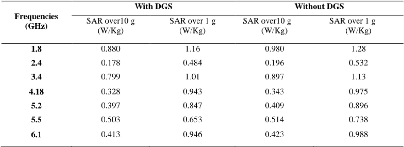
The values of SAR at different operating frequencies have been calculated for the proposed
structure with and without DGS (see Table 2). The value of SAR has been estimated over 1 g and 10 g
head tissues. It has been observed that the introduction of DGS in the ground plane reduces the
surface wave propagating along the substrate and reduces back radiation. Hence, antenna with DGS
has lesser SAR values as compared to antenna without DGS. This may be attributed to the
improvement in the radiation performance of the antenna. These values are well below the acceptable
limits set by ANSI/IEEE and FCC.
Table 2 SAR values of the designed antenna
Frequencies (GHz)
With DGS Without DGS
SAR over10 g (W/Kg)
SAR over 1 g (W/Kg)
SAR over10 g (W/Kg)
SAR over 1 g (W/Kg)
1.8 0.880 1.16 0.980 1.28
2.4 0.178 0.484 0.196 0.532
3.4 0.799 1.01 0.897 1.13
4.18 0.328 0.943 0.343 0.975
5.2 0.397 0.847 0.409 0.896
5.5 0.503 0.653 0.514 0.738
6.1 0.413 0.946 0.423 0.988
CONCLUSION
This paper presents a multiband MIMO antenna that can be used for multiple wireless
communication technologies such as GSM 1800/1900, WCDMA, Wi-Fi, wireless LAN, LTE etc. A
low profile meander line antenna with L strip has been used as a radiating element. In order to
achieve a multiband operation, two double U slots have been etched out in the ground plane of this
antenna that alter the overall current distribution on the ground plane and miniaturization up to 69%
has been reported. To enhance the isolation between two radiating elements of MIMO, a line slot has
waves and hence an isolation as high as -57 dB has been achieved at 1.8 GHz. Gain varies between
4.47 dBi to 8.35 dBi for all the resonant frequencies with maximum gain at 2.4 GHz. The envelope
correlation coefficient (ECC) and Specific Absorption Rate (SAR) are also in the acceptable limits.
The antenna prototype has been fabricated and the measured results are in good agreement with the
simulation results. Moreover, presented antenna is very compact, low cost, conformal and very simple
to design that shows very good radiation characteristics over its operating frequency bands.
REFERENCES
[1] Puente, C., Anguera, J., Borja, C., and Soler, J., “Fractal-Shaped Antennas and their Application to GSε 900/1800,” The Journal of the Institution of British Telecommunications Engineers, vol. 2, part 3, July 2001.
[2] Risco, S., Anguera, J., Andujar, A., Perez, A., and Puente, C., “ Coupled εonopole Antenna Design for εultiband
Handset Devices,” Microw. Opt. Technol. Lett., vol. 52, no. 10, pp. 359–364, Feb. 2010.
[3] Anguera, J., Puente, C., and Borja, C., “ Dual Frequency Broadband Microstrip Antenna With a Reactive Loading and
Stacked Elements,” Prog. Electromagn. Res. Lett., vol. 10, pp. 1-10, 2009.
[4] Jayasinghe, J.W., Anguera, J., and Uduwawala, D.N., “ A simple design of multi band microstrip patch antennas robust
to fabrication tolerances for GSε, UεTS, δTE, and Bluetooth applications by using genetic algorithm optimization,” Prog.
Electromagn. Res. M, vol. 27, pp. 255–269, 2012.
[5] Li, Q., Li, G., Lee, W., Lee, M., Mazzarese, D., Clerckx, B., and Li, Z, “εIεO techniques in WiεAX and δTE: A
feature overview,” IEEE Commun. Mag., vol. 48, no. 5, pp. 86–92, 2010
[6] Foschini, G.J., “On limits of wireless communications in a fading environment when using multiple antennas,” Wireless Pers. Commun., vol.6, no. 3, pp. 311–335, 1998.
[7] Najam, A., Duroc, Y., and Tedjni, S., “UWB-εIεO antenna with novel stub structure,” Prog. Electromagn. Res. C, vol. 19, pp. 245–257, Feb.2011.
[8] Chen, S.C., Wang, Y.S., and Chung, S.J., “A Decoupling Technique for Increasing the Port Isolation Between Two
Strongly Coupled Antennas,” IEEE Trans. Antennas Propag., vol. 56, no. 12, pp. 3650–3658, 2010.
[9] Tang, X., Mouthaan, K., and Coetzee, J.C., “Tunable Decoupling and εatching Network for Diversity Enhancement of
Closely Spaced Antennas,” IEEE Antennas Wireless Propag. Lett., vol.11, pp. 268 – 271, 2102.
[10] Yang, F., and Samii, Y.R., “εicrostrip Antennas Integrated With Electromagnetic Band-Gap (EBG) Structures: A Low
εutual Coupling Design for Array Applications,” IEEE Trans. Antennas Propag., vol. 51, no. 10, pp. 2936 – 2946, 2003.
[11] Tang, T.C., and Lin, K.H., “An ultrawideband εIεO antenna with dual band-notched function,” IEEE Antennas Wireless Propag. Lett., vol. 13, pp. 1076–1079, 2014.
[12] Chu, Q.X., and Chu, J.F., “A compact wider dual-band εIεO antenna array for mobile phone,” in Proc. IEEE Wireless Inf. Technol. Syst. Conf., Honolulu, HI, pp. 1–4, Aug. 2010.
[13] Lihao, H., Huiling, Z., Zhang, H., and Quanming, C., “Reduction of εutual Coupling between Closely-Packed Antenna
Elements with Split Ring Resonator (SRR),” Proc. ICMMT, pp. 1873 – 1875, 2010.
[14] Andujar, A., and Anguera, J., “ εIεO εultiband Antenna System with Non- Resonant Elements,” Microw. Opt. Technol. Lett., vol. 57, no. 1, pp. 183–190, Jan. 2015.
[15] Luo, C.M., Hong, J.S., and Zhong, L.L., “Isolation Enhancement of a Very Compact UWB-MIMO Slot Antenna With
Two Defected Ground Structures,” IEEE Antennas Wireless Propag. Lett., vol. 14, pp. 1766 - 1769, 2015.
[16] Lee, J.M., Kim, K.B., Ryu, H.K., and Woo, J.M., “”A Compact Ultrawideband MIMO Antenna With WLAN
Band-Rejected Operation for εobile Devices,” IEEE Antennas Wireless Propag. Lett., vol. 11, pp. 990 - 993, 2012.
[17] Soltani, S., and Murch, R.D., “A Compact Planar Printed εIεO Antenna Design,” IEEE Trans. Antennas Propag., vol.
[18] Ide, K., Ijiguchi, S., and Fukusako, T., “Gain enhancement of low-profile, electrically small capacitive feed antennas
using stacked meander lines,” International Journal Antennas Propag., Article ID 606717, pp. 8, 2010.
[19] Yang, S.M., and Huang, C.H., “An Inductor εodel for Analyzing the Performance of Printed εeander δine Antennas
in Smart Structures,” Journal Electromagnetic Analysis App, pp. 244-252., Aug. 2014.
[20] Blanch, S., Romeu, J., and Corbella, I., “Uniplanar slot antenna for ultrawideband polarization-diversity applications,” IEEE Antennas Wireless Propag. Lett., vol. 12, pp. 88–91, 2013.
[21] Thaysen, J., and Jakobsen, K.B., “Envelope correlation in (N;N) MIMO antenna array from scattering parameters,” Microw. Opt. Technol. Lett., vol. 48, pp. 832–834, 2006.
[22] Chacko, B.P., Augustin, G., and Denidni, T.A., “Uniplanar slot antenna for ultrawideband polarization-diversity
applications,” IEEE Antennas Wireless Propag. Lett., vol. 12, pp. 88–91, 2013.
[23] Han, M., and Choi, J., “Small-size printed εIεO antenna for next generation mobile handset application,” Microw. Opt. Technol. Lett., vol. 53, no. 2, pp. 248–352, Feb. 2011.
[24] Siegbahn, M., Babik, G.B., Keshvari, J., Christ, A., Derat, B., Monebhurrun, V., Penney, C., Vogel, M., and Wittig, T.,