ISSN 0104-6632 Printed in Brazil
www.abeq.org.br/bjche
Vol. 26, No. 04, pp. 677 - 683, October - December, 2009
Brazilian Journal
of Chemical
Engineering
DROP SIZE IN A LIQUID PULSED SIEVE-PLATE
EXTRACTION COLUMN
M. R. Usman, H. Sattar, S. N. Hussain, H. Muhammad, A. Asghar, and W. Afzal
*Institute of Chemical Engineering and Technology, Faculty of Engineering & Technology, University of the Punjab, Lahore, New Campus, 54590, Pakistan.
E-mail: [email protected]
(Submitted: November 13, 2008 ; Revised: March 23, 2009 ; Accepted: March 30, 2009)
Abstract - The (Benzoic acid + kerosene + water) system was studied in a 5.0 cm diameter liquid pulsed liquid-liquid extraction column with a total number of 80 sieve plates. The effect of pulsation intensity, dispersed phase superficial velocity, and continuous phase superficial velocity on volume-surface mean diameter was studied. Generally, the mean drop diameter decreased more rapidly with the increase of pulsation intensities and superficial velocities at low pulsation intensities and superficial velocities. However, the effect was not found to be significant at higher pulsation intensities and higher superficial velocities. In the interpretation of the experimental results, the drop size was observed to be a function of the operating regimes (mixer-settler, dispersion, and emulsion) of the pulsed sieve-plate extraction column. The experimental mean drop diameters were compared to the most acceptable analytical drop size correlation developed by Kumar and Hartland (1986). The correlation proved to be in good agreement for the column operating in the dispersion regime.
Keywords: Pulsation intensity; Superficial velocities; Mean drop diameter; Correlation; operating regimes.
INTRODUCTION
The design, optimization and operation of a pulsed sieve-plate extraction column require both mass transfer and hydrodynamic characteristics. Drop size affects almost all the parameters that influence hydrodynamics and mass transfer in a pulsed sieve-plate extraction column (Pietzsch and Pilhofer, 1984). Knowledge of drop size and distribution are necessary parameters for measuring mass transfer coefficients (Yaparpalvi et al., 1986) and aids in determining the efficiency of the extraction column (Pietzsch and Pilhofer, 1984). It influences the dispersed phase holdup and residence time (Kumar and Hartland, 1996) and the maximum capacity of the column (Pietzsch and Pilhofer, 1984 and Kumar and Hartland, 1996). Realizing the overwhelming importance of drop size, many investigators studied the effect of column operating variables on drop size and developed correlations for
estimating the mean drop size. Among these investigators, Misek (1964), Kagan et al. (1965), Miyauchi and Oya (1965), Assenov and Penchev (1971), Kubica and Zdunkiewicz (1977), Boyadzhiev and Spassov (1982), Schmidt (1983), Vassallo et al. (1983), Pietzsch and Pilhofer (1984), Kumar and Hartland (1986, 1996), Ikeda and Suzuki (1992), and Sreenivasulu et al. (1997) have developed their own drop size correlations. The analytical correlation of Kumar and Hartland (1986) is considered to be the most respectable among all the available correlations (Grinbaum, 2006) and selected for a comparison to the experimental data in this work.
was the continuous phase. The purpose of the study is to contribute more data, needed for developing and/or improving design strategies and scale up procedures for liquid pulsed columns by working on original systems, and to validate the most acceptable analytical expressions for the mean drop diameter. The set of new experimental data is used to test predictions of the Kumar and Hartland correlation (1986). In the interpretation of the experimental data and predictions of the Kumar and Hartland correlation (1986), it is observed that the efficiency of the method is related to the operating regimes (mixer-settler, dispersed, and emulsion). The method shows limitations in the mixer-settler regime potentially important in the plant start up and shut down routines.
EXPERIMENTAL
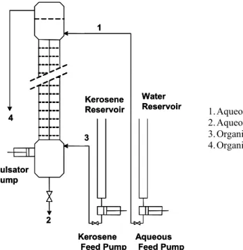
The experimental setup is shown in Figure 1. A pilot scale, 5.0 cm internal diameter glass sieve-plate pulsed extraction column was used for all the experiments undertaken. There were about 80, 1.0 mm thick stainless steel plates in the column and every two plates were separated 5.0 cm apart. Each plate contained 36 holes of 3.0 mm in diameter. The holes were laid out on a triangular pitch of 5.0 mm. The free area could not exceed 13.5% of the total area. Analytical grade benzoic acid from BDH
Chemicals (assay 99.5%) was used to make a ~ 2 mass % solution in Kerosene. 31°API kerosene with an ASTM 50% point of 110°C was employed, together with water available in the laboratory. Chemicals were used as such and no attempt was made to purify them further.
Firstly, the whole of the column was filled with the water (continuous phase), then the kerosene-benzoic acid solution (dispersed phase), being lighter, was introduced from the bottom of the column. The photographic method was employed for drop size diameter measurement in which the photographs at different time intervals were taken and, using a scale-ratio, the diameter of the drop is measured. Generally, on average about 50 readings were taken for each diameter value measured and used in this work. The 30th plate (counting from the bottom) was selected for the drop size observation and measurement. This decision was taken on the basis of convenience and the fact that drop formation was found to be more stable at this level. The drop size was found to be relatively less stable at lower levels of the column. All experiments were conducted at room temperature (20 ± 1° C) and conducted in the mixer-settler and dispersion regimes, since most of the industrial columns avoid being operated in the emulsion regime (Grinbaum, 2006). Table 2 provides information on all the variables that were studied in this work.
1
2
3 Kerosene Reservoir
Kerosene Feed Pump
Water Reservoir 4
Aqueous Feed Pump Pulsator
Pump
1
2
3 Kerosene Reservoir
Kerosene Feed Pump
Water Reservoir 4
Aqueous Feed Pump Pulsator
Pump
1.Aqueous phase in 2.Aqueous phase out 3.Organic phase in 4.Organic phase out
RESULTS AND DISCUSSION
Depending on the intensity of mixing, three separate flow regimes, namely mixer-settler, dispersion, and emulsion regimes, are characterized in the operation of a liquid pulsed extraction column (Grinbaum, 2006). Based on pulsation intensity, the approximate ranges for the three regimes are provided in Table 1. These ranges are only approximate and vary from system to system (Sreenivasulu et al., 1997). The mixer- settler regime is a region of low mixing and characterized by the discrete zones in the column, i.e., one of the phases may accumulate above or below each of the plates to produce discontinuity in the column. Dispersion regime avoids such discontinuity and dispersed phase drops are more uniformly distributed in the column. Emulsion regime is the operation of a highly intense mixing process where the column tends to approach flooding.
Table 1: Classification of Regimes in Liquid Extraction Columns (Sreenivasulu et al., 1997)
Regime Range (mm/s)
Mixer-settler Af < 15
Dispersion 15 < Af < 40
Emulsion Af > 40
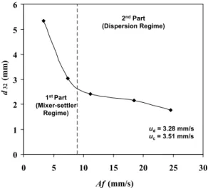
The effect of energy addition in the form of pulsation intensity or pulsation velocity, Af, on the mean drop diameter is shown in the Figure 2. The pulsation intensity is defined as the product of frequency of pulsation, f, and stroke length or amplitude of pulsation, A, whereas the mean drop diameter is taken as the volume-surface mean diameter or Sauter mean diameter, d32. The following
expression is used for calculating the Sauter mean diameter:
i n i n
3 2
32 i i
i 1 i 1
d d d
= =
= =
=
∑ ∑
(1)It was observed that the mean drop diameter decreases with an increase in the pulsation intensity. This is in accordance with the expectations because an increase in pulsation intensity is a function of energy added to the column contents. However, an interesting point may be explained by dividing the curve in Figure 2 in two parts. The first part, defined between pulsation intensity of 3.3 and 9.0 mm/s, is characterized by a relatively sharp decrease in the
mean diameter as compared to the second part, which comprises the range 9.0 mm/s to 24.6 mm/s. It was visually observed that the first two points of the curve lay in the mixer-settler regime, while the other three belonged to the dispersion regime. So the end of the first part may be the transition region from the mixer-settler regime to the dispersion regime. It is thus interpreted that the effect of pulsation intensity on mean drop diameter is more pronounced in the mixer-settler regime than in the dispersion regime.
0 1 2 3 4 5 6
0 5 10 15 20 25 30
Af(mm/s)
d
32
(m
m
)
1st Part (Mixer-settler
Regime)
2ndPart (Dispersion Regime)
u
d= 3.28 mm/s
uc= 3.51 mm/s
0 1 2 3 4 5 6
0 5 10 15 20 25 30
Af(mm/s)
d
32
(m
m
)
0 1 2 3 4 5 6
0 5 10 15 20 25 30
Af(mm/s)
d
32
(m
m
)
1st Part (Mixer-settler
Regime)
2ndPart (Dispersion Regime)
u
d= 3.28 mm/s
uc= 3.51 mm/s
Figure 2: Effect of pulsation intensity on mean drop diameter and the representation of mean diameter as
a function of flow regimes (refer to Table 2)
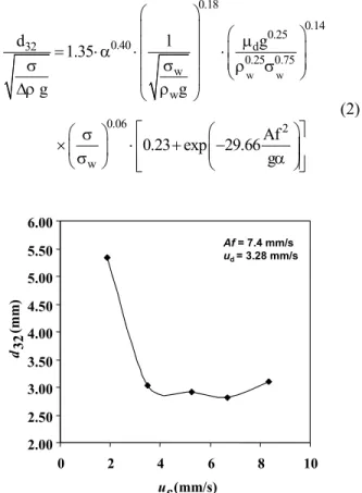
Figure 3 represents the influence of dispersed phase (kerosene) superficial velocity, ud, on the
typical size distribution in the form of a histogram between the percent number of drops and the Sauter mean diameter, d32, of the corresponding group is
plotted in Figure 5.
The comparison of Figure 3 and Figure 4 reveals the fact, that in the lower velocity region (lower end of mixer-settler regime), dispersed phase velocity produces much smaller drop sizes as compared to continuous phase velocity. As an example, the value of drop size is 3.17 mm at ud equal to 1.67 mm/s,
while drop diameter is much larger, 5.33 mm, when uc is equal to 1.87mm/s. In this region, an increase in
the continuous phase velocity sharply decreases the drop diameter, but the same is not true for the dispersed phase velocity. At higher velocities (upper end of mixer-settler region), the effect of either phase velocity is virtually the same; however, smaller diameter is always obtained with ud.
Figures 6 and 7 give a comparison between the experimental diameters and those calculated from the
most recommended equation, Eq. 2 developed by Kumar and Hartland (1986) for the prediction of drop diameter in a pulsed sieve-plate column. Table 2 gives the experimentally measured diameters, while Table 3 includes the physical properties and the column characteristics that are employed with the Kumar and Hartland correlation to compare the calculated and experimental diameters.
The correlation of Kumar and Hartland (1986) is shown below: w w 0.18 0.14 0.25 0.40 32 d 0.25 0.75 w w 0.06 2 w
d l g
1.35
g g
Af 0.23 exp 29.66
g
⎛ ⎞
⎜ ⎟ ⎛ ⎞
μ
⎜ ⎟ ⎜ ⎟
= ⋅α ⋅⎜ ⎟ ⋅
⎜ ⎟
σ σ ⎝ρ σ ⎠
⎜ ⎟
Δρ ⎝ ρ ⎠
⎡ ⎛ ⎞⎤
⎛ σ ⎞
×⎜σ ⎟ ⋅⎢ + ⎜⎜− α⎟⎟⎥
⎢ ⎥ ⎝ ⎠ ⎣ ⎝ ⎠⎦ (2) 2.00 2.20 2.40 2.60 2.80 3.00 3.20 3.40
0 2 4 6 8 10
ud(mm/s)
d
32
(m
m
)
Af= 7.4 mm/s
u
c= 3.51 mm/s
2.00 2.20 2.40 2.60 2.80 3.00 3.20 3.40
0 2 4 6 8 10
ud(mm/s)
d 32 (m m ) 2.00 2.20 2.40 2.60 2.80 3.00 3.20 3.40
0 2 4 6 8 10
ud(mm/s)
d
32
(m
m
)
Af= 7.4 mm/s
u
c= 3.51 mm/s
2.00 2.50 3.00 3.50 4.00 4.50 5.00 5.50 6.00
0 2 4 6 8 10
uc(mm/s) d32
(m
m
)
Af= 7.4 mm/s
ud= 3.28 mm/s
2.00 2.50 3.00 3.50 4.00 4.50 5.00 5.50 6.00
0 2 4 6 8 10
uc(mm/s) d32
(m
m
)
Af= 7.4 mm/s
ud= 3.28 mm/s
Figure 3: Effect of dispersed phase superficial velocity on the mean drop diameter
(refer to Table 2)
Figure 4: Effect of continuous phase superficial velocity on the mean drop diameter
(refer to Table 2)
0 10 20 30 40 50
1.41 1.79 2.17 2.55 2.93 3.32 3.70 4.08 Droplet diameter, d32(mm)
% N o . o f d ro p s
d32= 2.92 mm ud= 3.28 mm/s uc= 5.26 mm/s
Af = 7.4 mm/s
0 10 20 30 40 50 0 10 20 30 40 50
1.41 1.79 2.17 2.55 2.93 3.32 3.70 4.08 1.41 1.79 2.17 2.55 2.93 3.32 3.70 4.08
Droplet diameter, d32(mm)
% N o . o f d ro p s
d32= 2.92 mm ud= 3.28 mm/s uc= 5.26 mm/s
Af = 7.4 mm/s
0 1 2 3 4 5 6
0 5 10 15 20 25 30
Af(mm/s) d 32 (m m ) Experimental
Calculated (Eq. 2)
1stPart (Mixer-settler
Regime)
2ndPart (Dispersion Regime)
ud= 3.28 mm/s
u
c= 3.51 mm/s
0 1 2 3 4 5 6
0 5 10 15 20 25 30
Af(mm/s) d 32 (m m ) Experimental
Calculated (Eq. 2)
0 1 2 3 4 5 6
0 5 10 15 20 25 30
Af(mm/s) d 32 (m m ) Experimental
Calculated (Eq. 2)
1stPart (Mixer-settler
Regime)
2ndPart (Dispersion Regime)
ud= 3.28 mm/s
u
c= 3.51 mm/s
0 1 2 3 4 5 6
0 1 2 3 4 5 6
d32, Experimental (mm) d32 fr o m E q . 2 ( mm) 11
Af = 7.4 mm/s, ud = 3.28 mm/s
ud = 3.28 mm/s, uc = 3.51
mm/s
Af= 7.4 mm/s, uc= 3.51 mm/s Af= 7.4 mm/s, ud= 3.28 mm/s ud= 3.28 mm/s, uc= 3.51 mm/s
0 1 2 3 4 5 6
0 1 2 3 4 5 6
d32, Experimental (mm) d32 fr o m E q . 2 ( mm) 11
Af = 7.4 mm/s, ud = 3.28 mm/s
ud = 3.28 mm/s, uc = 3.51
mm/s 0 1 2 3 4 5 6
0 1 2 3 4 5 6
d32, Experimental (mm) d32 fr o m E q . 2 ( mm) 11
Af = 7.4 mm/s, ud = 3.28 mm/s
ud = 3.28 mm/s, uc = 3.51
mm/s
Af= 7.4 mm/s, uc= 3.51 mm/s Af= 7.4 mm/s, ud= 3.28 mm/s ud= 3.28 mm/s, uc= 3.51 mm/s
Figure 6: Comparison of diameters with the variation in pulsation intensity
(refer to Table 2)
Figure 7: Comparison of experimental diameters with diameters calculated from Eq. (2)
(refer to Table 2 and Table 3)
Table 2: Experimental Variables and Measured Experimental Diameter
Frequency, f (Hz) Amplitude, A (mm) Continuous phase velocity, uc
(mm/s)
Dispersed phase velocity, ud
(mm/s)
d32, measured experimentally
(mm)
0.165 20.0 3.51 3.28 5.32 0.370 20.0 3.51 3.28 3.03 0.370 20.0 3.51 1.67 3.19 0.370 20.0 3.51 5.13 2.56 0.370 20.0 3.51 6.70 2.45 0.370 20.0 3.51 8.33 2.43 0.370 20.0 1.87 3.28 5.33 0.370 20.0 5.26 3.28 2.92 0.370 20.0 6.70 3.28 2.82 0.370 20.0 8.33 3.28 2.49 0.560 20.0 3.51 3.28 2.40 0.925 20.0 3.51 3.28 2.15 1.230 20.0 3.51 3.28 1.76
Table 3: Physical Properties and Column Characteristics Used with Eq. 2
Parameter Value with working units
ρw 998.2 kg/m3
μw 0.00100 Pa.s
σw 0.0728 N/m
Δρ 198.0 kg/m3
μd 0.00167 Pa.s
σ 0.0440 N/m
l 0.050 m
α 0.135
The single correlation is developed to apply in all the three operating regimes discussed above. The equation is based on 16 different liquid-liquid systems and 326 published drop size measurements (Kumar and Hartland, 1986). The effect of system geometry, pulsation intensity, and physical
properties of phases is included. The effect of phase superficial velocities is not incorporated.
mixer-settler regime and the dispersion regime. However, it performs poorly in most of the mixer-settler region, especially at the lower end of the mixer-settler region (where a significant effect of both continuous and dispersed phase velocity is observed, Figures 3 and 4) and then improves along the way. The maximum deviation between the measured and calculated drop sizes reaches as high as 50% in the lower end of the mixer-settler region, but this deviation is generally less than 10% in the dispersion region. The poor results do not discourage the use of Eq. 2 for prediction of drop diameter because of the fact that it covers the practical operating ranges of the industrial columns. However, if the column is operated in the region described here as the lower end of mixer-settler regime, the use of the above equation should be avoided. This situation can be encountered during column start up and shut down routines. Figure 7, on the other hand, gives a comparison under all conditions studied in this work. It reveals the fact that the efficacy of Eq. 2 is more disturbed by the variations in continuous phase superficial velocity than dispersed phase superficial velocity. The maximum deviation reaches as high as 53% in the case of continuous phase, while about 21% in the case of dispersed phase velocity.
CONCLUSIONS
The energy input in the form of pulsation intensity has a profound effect on the mean drop diameter and an increase in the value decreases the mean drop size. Drop size seems to be a function of governing regime (mixer-settler or dispersion). The effect of superficial velocities on drop diameter is very much pronounced in the lower end of the mixer-settler region and the change in the continuous phase velocity has a larger effect on drop diameter in this region. The analytical equation of Kumar and Hartland (1986) proved to be very appropriate in the region of practical interest, i.e., near the end of mixer-settler regime and within the dispersion regime; however, it failed in the lower end of the mixer settler region. This is the region where superficial velocities have a profound effect on diameters.
ACKNOWLEDGMENTS
Support staff at the Unit Operations Laboratory, Institute of Chemical Engineering and Technology, University of the Punjab, Lahore, is gratefully
acknowledged for the maintenance of the experimental facilities.
NOMENCLATURE
A stroke length or pulsation amplitude
m
d32 volume-surface mean or
Sauter mean drop diameter
m
f frequency of pulsation s-1 g acceleration due to gravity m/s2
l distance between sieve-plates
m
c
u continuous phase superficial velocity
m
d
u dispersed phase superficial velocity
m
α fractional free area of the plate
d
μ viscosity of the dispersed phase
Pa.s
w
ρ density of water at 20°C kg/m3 Δρ density difference between
heavier and lighter phases
kg/m3 σ interfacial tension N/m
w
σ surface tension of water at 20°C
N/m
i ith value n nth value
REFERENCES
Assenov, A., Penchev, I., Effect of pulsing intensity upon droplet size in a plate pulsed extraction column, Dokl. Bolg. Akad. Nauk. 24, 1381-1387 (1971).
Boyadzhiev, L. and Spassov, M., On the size of drops in pulsed and vibrating plate extraction columns, Chem. Eng. Sci. 37, 337-340 (1982). Grinbaum, B., Review Article: The existing models
for simulation of pulsed and reciprocating columns—How well do they work in the real world? Solvent Extraction and Ion Exchange, 24, 795-822 (2006).
Ikeda, H. and Suzuki, A., Plate wettability and droplet diameter in a pulsed perforated plate extraction column, Can. J. Chem. Eng. 70, 232-236 (1992). Kagan, S. Z., Aerov, M. E., Lonik, V. and Volkova,
Kubica, J., Zdunkiewicz, D., Drops mean diameter of dispersed phase in a pulsed extraction column with louver or sieve plates, Inz. Chem. 7, 903-907 (1977).
Kumar, A. and Hartland, S., Prediction of drop size in pulsed perforated-plate extraction columns, Chem. Eng. Commun., 44, 163-182 (1986). Kumar, A. and Hartland, S., Unified Correlations for
the predictions of drop size in liquid-liquid extraction columns, Ind. Eng. Chem. Res. 35, 2682-2695 (1996).
Misek, T., The hydrodynamic behaviour of pulsed liquid-liquid extractors, Collect. Czech. Chem. Commun. 29, 1755-1761 (1964).
Miyauchi, J., Oya, H., Longitudinal dispersion in pulsed perforated-plate columns, AIChE J. 11 395-402 (1965).
Pietzsch, W. and Pilhofer, T. H., Calculation of the drop size in pulsed sieve-plate extraction columns Chem. Eng. Sci. 39:961-965 (1984).
Schmidt, H., Holdup, Drop size and axial mixing of pulsed extraction column. Proc. Int. Solv. Extr. Conf. (ISEC’83), 1, 164-165 (1983).
Sreenivasulu, K., Venkatanarasaiah, D., and Varma, Y. B. G., Drop size distributions in liquid pulsed columns, Bioprocess Eng. 17: 189-195 (1997).
Vassallo, G., Thornton, J. D., Dworschak, H., The hydrodynamic behaviour of a pulsed perforated plate column, Proc. Int. Solv. Extr. Conf. 1 (ISEC’83) 168-169 (1983).