ISSN 0104-6632 Printed in Brazil
www.abeq.org.br/bjche
Vol. 25, No. 03, pp. 435 - 442, July - September, 2008
*To whom correspondence should be addressed
Brazilian Journal
of Chemical
Engineering
ELECTROFLOTATION OF EMULSIFIED OIL IN
INDUSTRIAL WASTES EVALUATED WITH
A FULL FACTORIAL DESIGN
F. N. B. Nahui
1,
M. R. Nascimento
2, E. B. Cavalcanti
3and E. O. Vilar
4*1
Universidade Federal de Campina Grande, Unidade Acadêmica de Mineração e Geologia, Phone: +(55) (83) 3310-1314, Fax: +(55) (83) 3310-1114, Av. Aprígio Veloso 882,
CEP 58109-970, Campina Grande - PB, Brazil, E-mail: [email protected]
2
Escola Agrotécnica Federal de Sousa, PB EAFS-PB, Rua Presidente Tancredo Neves, s/n, CEP: 58.805 970, Jardim Sorrilândia, Sousa - PB, Brazil.
E-mail: [email protected]
3
Instituto de Tecnologia e Pesquisa, ITP, Universidade Tiradentes, UNIT, Av Murilo Dantas 300, CEP: 49032-490, Farolândia, Aracajú - SE, Brazil.
E-mail: [email protected]
4
Universidade Federal de Campina Grande, Unidade Acadêmica de Engenharia Química, Laboratório de Engenharia Eletroquímica, Phone: +(55) (83) 3310-1314,
Fax: +(55) (83) 3310-1114, Av. Aprígio Veloso 882, CEP 58109-970, Campina Grande - PB, Brazil,
E-mail: [email protected]
(Received: February 1, 2007 ; Accepted: February 28, 2008)
Abstract - The use of electroflotation in emulsified oil wastes was studied. A rectangular electroflotation cell was designed and constructed in acrylic with stainless steel cathode and DSA® anode with a nominal composition of Ti/Ru0.34Ti0.66O2. The variables studied in the present work were current density and oil,
flocculant and electrolyte (NaCl) concentrations. The experiments were carried out in accordance with 24 full factorial experimental designs with two center points. The STATISTICA 5.5 software was used for calculations in order to relate experimental data to a statistical model. The best results, yielded 99.71% oil removal were obtained from 1050ppm of emulsified oil feed.
Keywords: Electroflotation; Emulsified oil; Industrial waste water; Factorial design.
INTRODUCTION
The development of new techniques for treatment of wastewater with high salinity from the petroleum industry has been a challenge due to the increase in production in Brazil. Voluntary or involuntary spilling of oil in different kinds of water is an issue of environmental concern. The high salinity and large volumes normally involved prevent the use of traditional biological processes. Conventional biological processes are there ruled out due to the requirement of large plant and skilled technicians. In
control only by adjusting the current makes automation quite easy operation and offers simplicity and low capital and operating costs (Hosny et al, 1992 Calvin et al, 1997). Recently, Ben Mansur and Chalbi (2006) examined the effect of operating parameters such as current density, oil concentration, flotation time and coagulant concentration on the performance of the electroflotation cell. Oil removal reached 70% under optimum conditions 75% with NaCl (3.5% by wt) and 99.5% with both NaCl and an optimum concentration of coagulant. Electrical energy consumption varied from 0.4 to 1.6 kWhm-3 under the experimental conditions. The performance of the oil removal process was also represented by a first-order kinetic model. The constants obtained fit the experimental data well. The electroflotation mechanism for wastewater treatment is very complex. It is generally believed that there are other possible mechanisms involved besides electroflotation, i.e. electrocoagulation, electrochemical oxidation and adsorption. Nevertheless, all the mechanisms highly depend on charge loading (Koren et al, 1995). A few studies applied an insoluble anode for removal processes (Kholsa et al, 1991 and Chen et al, 2000). The electrode assembly is the heart of the present treatment facility. Therefore, careful selection of its materials is very important. The most common electrode materials for electroflocculation are aluminum and iron (Khosla et al, 1991 and Chen et al, 2000).
In general most optimization studies during the development of a process involve varying one factor at a time, keeping other factors constant. Factorial designs conducted in a completely randomized manner enable all factors to be varied simultaneously, thus allowing quantification of the effects caused by independent variables and interactions between them. Another important advantage is that experimental designs can be changed progressively until a fitted model is found to describe the studied phenomenon. This article evaluates the effect of four parameters on electroflotation of emulsified solution using the factorial experimental design. Statistical models to quantity the effect of these parameters, individually and/or jointly, were determined.
MATERIALS AND METHOD
A rectangular electroflotation cell was constructed of acrylic with the dimensions 8 cm x 9 cm and a height of 30 cm. Stainless steel and DSA® (Ti/Ru0.34Ti0.66O2) both expanded materials
connected in a monopolar mode were used as cathode and anode, respectively. The electrodes were positioned horizontally at the bottom of the cell. The gap between the electrodes was 1.5cm. The cathode and anode areas of 98.3 x 10⁻⁴ m2 and 154 x 10-4 m2, respectively, were calculated using the Image Tool version 1.2 software. A schematic diagram of the experimental set-up is shown in Figure 1. The synthetic emulsions (350 mg/L) was prepared from diesel oil (Petrobrás Company) and Tween 20 as emulsifier from Oxiteno S.A.. The emulsion volume in the cell was 1.5L. The pH was adjusted to 4.5 with HCl. In order to examine the effect of salinity on oil removal efficiency, NaCl was added to synthetic emulsions to vary their conductivity. The flocculant used was a polyelectrolyte ironsalt from Clarient S.A. An electroflotation time of 30 min was utilized. After process, the cell was cleaned carefully to remove any oil contamination. The potential applied and current obtained were measured by a digital DC power supply model CA-CG EMG. The concentrations of oil before and after electrolysis were measured with a Hach DR/2000 spectrophotometer.
A four-factor, two-level (24) factorial design which corresponds to 16 different experiments was established. Two additional curves, for which the values variables is determined by the central point, were used (see Table 2: experiments no 17 and 18). Based on the data obtained using this experimental design, equations were generated to establish the correlation between the independent variables (i.e., oil, flocculant and electrolyte (NaCl) concentrations and current density) and the dependent variables (i.e., percentage oil removal and energy consumption). The equations were validated by the following statistical tests: Analysis of variance (ANOVA) was used to determine the significance of each term in the equations fitted and to estimate the goodness of fit in each case. The calculated F-value was compared to the theoretical F-value, Fα(p-1,
n-p), where α is the chosen risk, set in this study at 0.05; n is the total number of experiments and p is the number of terms in the model and explained variance (%). The response surface methodology (RSM) was used to analyze the experimental design. The response variable was fitted by a first-order model in order to correlate the response to the respective independent variables. The general form of the first-degree equation is
i 0 i i ij i j
Brazilian Journal of Chemical Engineering Vol. 25, No. 03, pp. 435 - 442, July - September, 2008
where Yi is the predicted response, xi and xj are input variables which affect variable Y and β0 is the offset term and βi is the ith linear coefficient;
βij is the ijth interaction coefficient. The coefficients were calculated using the STATISTIC software (version 5.5).
From experimental observations, it was assumed that the higher order interactions were small relative to the low order interactions because a system with several process variables is conducted primarily by
some of the main effects and low-order interactions. Therefore, the present work considers only two-way interactions. The other higher order interactions were added into the error. The center points could be used to check the curvature in the model to be fitted. The main variables Xoil, Xfloc, XNaCl and Xi represent oil, flocculant, electrolyte concentration and current density, respectively. The levels for the four main variables were chosen from our previous experiments. The original values of the variables are shown in Table 1.
Overflow
in
Sample
out
Power supply - DC
Valve
Centrifugal pump
Flowmeter Tank
Thermostat
Figure 1: Schematic diagram of the system.
Table 1: Original variables.
Main variable Original variable(X) -1 0 +1
[oil] ppm Xoil 200 625 1050
[floc] ppm Xfloc 4 18 32
i A m-2 Xi 19.48 126.62 233.76
RESULTS AND DISCUSSION
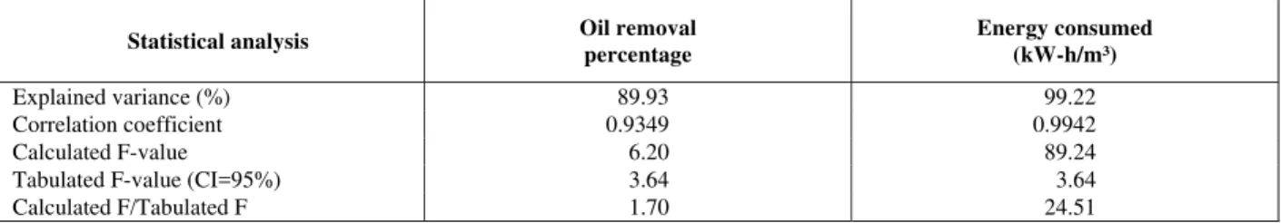
The matrix of experiments and results are presented in Table 2. The corresponding analysis of variance (ANOVA) is presented in Table 3. The calculated F-value is greater than the tabulated F-F-value, F0.95,1,.7 = 3.64 at α = 0.05 level so the null hypothesis (Ho) is rejected. Having rejected the null hypothesis, it can be inferred that treatment differences are highly significant. Also, the high F-value and a very low probability indicate that the present model provides a good prediction a experiments results (as a practical rule, a model has statistical significance when the calculated F-values are at least three to five times greater than the tabulated F-values) (Barros et al, 1996).
The variables chosen for the optimization procedure are those that could affect the percentage oil removal. The main and interaction effects of the
four variables are given in Table 4.
The significant effects are indicated in boldface. It was observed that the flocculant concentration does not have statistical significance (αfloc = 0.4549) for oil removal, but it is important to the flocculation process (Hosny, 1992, 1996; Ben Mansur and Chalbi, 2006). Therefore if we take the statistical point of view we can eliminate the Xfloc variable column presented in Table 2 and proceed through the 23 experimental factorial analysis. In the same Table 4, it can also be observed that the effect of flocculant and oil concentrations on energy consumption is not statistically significance (αoil = 0.844 and αfloc = 0.92), so we can simplify the model by eliminating the Xoil and Xoil and Xfloc variable columns in Table 2 an repeat the 22 four times experimental factorial design (Rodrigues and Lemma, 2005). In Table 5 the new results of variance measurements are shown.
Table 2: 24 full factorial experiment design with two center points.
Experiment Xoil Xfloc Xi XNaCl
Oil removal percentage
Energy consumption (kWh/m3)
1 -1 -1 -1 -1 75.00 0.2
2 +1 -1 -1 -1 95.33 0.173
3 -1 +1 -1 -1 82.50 0.206
4 +1 +1 -1 -1 96.57 0.18
5 -1 -1 +1 -1 93.00 4.56
6 +1 -1 +1 -1 98.66 4.52
7 -1 +1 +1 -1 93.50 4.52
8 +1 +1 +1 -1 98.76 4.48
9 -1 -1 -1 +1 91.00 0.163
10 +1 -1 -1 +1 98.76 0.167
11 -1 +1 -1 +1 92.00 0.167
12 +1 +1 -1 +1 97.43 0.167
13 -1 -1 +1 +1 96.00 3.36
14 +1 -1 +1 +1 99.62 3.28
15 -1 +1 +1 +1 97.00 3.32
16 +1 +1 +1 +1 99.81 3.32
17 0 0 0 0 99.04 1.54
18 0 0 0 0 99.04 1.54
Table 3: Analysis of variance (ANOVA) for percentage oil removal and energy consumption.
Statistical analysis Oil removal
percentage
Energy consumed (kW-h/m³)
Explained variance (%) 89.93 99.22
Correlation coefficient 0.9349 0.9942
Calculated F-value 6.20 89.24
Tabulated F-value (CI=95%) 3.64 3.64
Brazilian Journal of Chemical Engineering Vol. 25, No. 03, pp. 435 - 442, July - September, 2008
Table 4: The main and interaction effects of the four variables.
Variables Percentage oil removal Energy consumed
(kWh/m3)
Mean 94.84 1.96
Yoil 8.11 -0.02
Yfloc 1.27 -0.01
Yi 5.97 3.74
YNaCl 4.78 -0.61
YoilYfloc -1.22 0.009
Yoil Yi -3.78 -0.01
Yoil YNaCl -3.21 0.007
Yfloc Yi -0.82 -0.012
Yfloc YNaCl -1.06 0.008
Yi YNaCl -2.66 -0.588
Table 5: Analysis of variance (ANOVA) for percentage oil removal and energy consumption.
Statistical analysis Oil removal
percentage
Energy consumed (kW-h/m3)
Explained variance (%) 87.10 99.98
Correlation coefficient 0.933 0.999
Calculated F-value 12.37 32,938.95
Tabulated F-value (CI = 95%) 3.09 3.49
Calculated F/Tabulated F 4 9,437.82
The statistical models expressed by equations (2) and (3) were generated, representing where percentage oil removal and energy consumption as a function of the variables, where the more significant are in boldface, respectively. Because the calculated F-value is higher than the tabulated F-value, both equations are statistically significant and useful for predictive purposes.
-5 -6
%R = (66.01173 ± 4.347866) +
(0.024325 ± 0.005016)×[oil] +
(0.08484 ± 0.020761)×i +
(0.00063 ± 0.000155)×[NaCl] -
(4×10 ± 1.6×10 )×[oil]×i
(2)
-6 -6
EC = -(0.266295 ± 0.025450) +
(0.024325 ± 0.000153)×i +
(4×10 ± 1×10 )×[NaCl]
(3)
Inspection of the values shown in Table 5 reveals that both the dependence of the percentage oil removal and EC response are more complicated than can be described by just two principal effect values alone.
If Xfloc does not really affect percentage oil removal,
one can expect the results for experiments 1 and 3, 2and 4 …14 and 16 to be the same within experimental error, since these pairs of experiments have identical conditions for Xoil, Xi and XNaCl. Inspection of the values in Table 2 confirms this observation. The variation in percentage oil removal is shown as a function of the interaction variables current density and oil and electrolyte (NaCl) concentrations. Data in Table 2 may also be plotted with each axis corresponding to one factor. Figure 2 confirms the simple behaviour for % oil removal values.
Xoil Parameter
Figure 2: 24 factorial design diagram for the average values of percentage for oil removal responses.
Xi Parameter
On comparing pairs of experiments that differ only by Xi, for example runs 1 and 5, 2 and 6, etc, the percentage oil removal values increase with a change in amount of gas production - 19.48 A.m-2 to 233.76 A.m-2 current density. This is consistent with the value of the positive main effect for Yi in Table 4. In other words, the percentage oil removal response is dependent on current density. The absolute value of percentage oil removal increases approximately 14.5% when the density current is changed, Xoil is 200 ppm and XNaCl is 15,000 ppm, irrespective of the value of Xfloc. Similar behavior is also observed when XNaCl is 35,000 ppm, except for a small increase of about 5% in percentage oil removal. This difference of about 9.5% is independent of Xfloc and can probably be explained by the fact that the salt (NaCl) decreases the size of the bubbles. In this case, it is necessary a high current density to produce the rupture of the linking of emulsified oil drops in a bigger volume of dispersant. However, when the oil concentration is higher than 1050 ppm, the rupture becomes easier to low current density (19.48 A.m-2) due to the existence of a bigger interaction contact surface between the gas bubble-oil particle.
The amount of bubbles electrochemically generated is significant when the salt concentration
increases to 35,000 ppm, the size of bubbles diminishes and the bubble contribution is reduced to 9% in this case indicating that the size of bubbles is an important factor in producing a larger active contact area between the bubbles and oil drops.
XNaCl Parameter
Comparing pairs of runs that differ only by XNaCl, runs 1 and 9, 2 and 10, etc. the percentage oil removal value increase when XNaCl is at its highest level, i.e., this factor has a positive effect corresponding to YNaCl Table 4. This is an important characteristic due to the reduction in bubble size.
Brazilian Journal of Chemical Engineering Vol. 25, No. 03, pp. 435 - 442, July - September, 2008
can be collected, and in the present work, the percentage oil removal goes from 78.7% to approximately 96.50%.
The factorial design diagram show in Fig 3 is also useful for choosing optimal conditions. In the present case, there is a optimal region between 220 and 260 A m-2 and 14000 and 24000 ppm of NaCl that produces a better percentage oil removal than the initial concentration of 1050 ppm. These conditions were found to have the best performance in the present work.
Energy Consumption
Energy consumption EC (kwh.m-3) was calculated with the following equation:
V
UI EC
Q 1000
= (4)
where U is the cell potential; I, the electrolysis current; and Qv, the volumetric flow rate, m³ h-1.
In Figure 4 it is shown that energy consumption varied from 0.48 to 4.5 kwh m-3 in a current density range of 19.48 to 233.76 A m-2, when the salt concentration was at the minimum. For a salt concentration around the maximum value, of energy consumption varied from 0.48 to 4.0 kwh m-3, between the minimum and maximum current densities. The same effect was also identified by Chen et al. [2000; 2002]. Using a salt concentration of approximately 39000 ppm Hosny [1992; 1996] obtained an energy consumption of 2.66 kwhm-3 applying 100Am-2, in an electroflotation cell with lead anodes.
The energy consumed to remove 100% of the oil calculated by equation (3) in the present work is about 13% lower than that obtained by Hosny [1996] to remove 75% with the same current density utilized, as shown in Table 6. This difference can be attributed to the DSA utilized that has better electrocatalytic properties and consequently a lower oxidation potential than the lead anode to produce chlorine gas.
Figure 3: Response surfaces for percentage oil removal: Effects of i and [NaCl]
([oil] = 1050 ppm).
Figure 4: Response surfaces on energy consumption: Effects of i and [NaCl] ([oil] = 625 ppm,
[floc] = 18 ppm).
Table 6: Present results compared with those of another author [Hosny, 2006].
Hosny Present work
[NaCl], ppm 39,000 35,000
CE, kWh/m² 2.66 2.38 (Eq. 2)
i, A/m² 100 100
%R 75 100 (Eq. 3)
[oil], ppm 1050 1050
pH of emulsion 4.5 4.5
Electrode gap, cm 1.5 1.5
Electrode lead DSA
CONCLUSIONS
The rate of oil drop flotation was improved for smaller bubbles. The agglomeration of oil drops by contact with ascending gas was better with microbubbles due to the large surface area of contact. Oil removal by electroflotation was strongly affected by initial concentration, increasing the conversion from 78.70 to 95.90%. The increase in current density and salinity improved oil removal. With the experiments, it was proved that it is possible to remove about 99% of the oil using a current density of 19.40 Am-2 with an energy consumption of 0.167kw-hm-3.
NOMENCLATURE
EC energy consumption kWh/m3, equation (3)
I Electric current A
%R percentage oil removal %, equation (2)
x input variables (-)
Xoil, oil concentration ppm Xfloc, flocculent concentration ppm XNaCl electrolyte concentration ppm
Xi current density A/m²
Yi the predicted response (-)
β0 offset term equation (1) i Coefficient equation (1) j Coefficient equation (1)
ACKNOWLEDGEMENTS
The authors wish to thank PROSET/CT-petro/CNPq and PRODOC/CAPES for their financial support of this work. We also thank Msc. M.F.Vieira (CTCC/SENAI-PB) for helping with analysis of the oil and Oxiteno S.A. and Petrobras for suppling the Tween 20 emulsifier and flocculant, respectively.
REFERENCES
Al-Shamrani, A. A., James, A. and Xiao, H., Destabilization of Oil-Water Emulsions and
Separation by Dissolved Air Flotation, Water Research, 36 (6), 1503-1512 (2002).
Al-Shamrani, A. A., James, A. and Xiao, H., Separation of Oil from Water by Dissolved Air Flotation, Colloids and Surfaces A: Physicochemical and Engineering Aspects, 209 (1), 15-26 (2002). Barros, N. B., Scarminio, I. S. and Bruns, R. E.,
Planejamento e Otimização de Experimentos, Editora da Unicamp, São Paulo (1996).
Ben Mansur, L. and Chalbi, S., Remove of Oil from Oil/Water Emulsions using Electroflotation Process, Journal of Applied Electrochemistry, 36, 577-581 (2006).
Burns, S. E., Yiacoumi, S. and Tsouris, C., Microbubble Generation for Environmental and Industrial Separations, Separation and Purification Technology, 11, 221-232 (1997). Calvin, P. C. P., Electroflotation for Groundwater
Decontamination, Journal of Hazardous Materials, 55, 150-170 (1997).
Chen, X. Chen, G. and Yue, P. L., Investigation on the Electrolysis Voltage of Electrocoagulation, Chemical Engineering Science, 57, 2449-2455 (2002).
Chen, X., Chen, G. and Yue, P. L, Separation of Pollutants from Restaurant Wastewater by Electrocoagulation, Separation and Purification Technology, 19, 65-76 (2000).
Hosny, A. Y., Separation of Oil from Oil/Water Emulsions Using an Electroflotation Cell with Insoluble Electrodes, Filtration & Separation, 29 (5), 419-423 (1992).
Hosny, A. Y., Separation of Oil from Oil/Water Emulsions by electroflotation technique, Filtration & Separation, 6 (1), 9-17 (1996).
Khosla, N. K., Venkatachalam, S. and Somasundaran, P., Pulsed Electrogeneration of Bubbles for Electroflotation, Journal Appl. Electrochem, 21, 986 (1991).
Koren, J. P. K. and Syversen, U., State-of-the-Art Electroflocculation, Filtration & Separation, 32 (2), 153-156 (1995).


![Table 6: Present results compared with those of another author [Hosny, 2006].](https://thumb-eu.123doks.com/thumbv2/123dok_br/18894539.425979/7.918.102.820.894.1048/table-present-results-compared-author-hosny.webp)
