Structure, morphology and magnetism of an ultra-thin [NiO/CoO]/PtCo bilayer with
perpendicular exchange bias
Helio C. N. Tolentino, Maurizio De Santis, Jean-Marc Tonnerre, Aline Y. Ramos, Veronique Langlais, Stephane Grenier, and Aude Bailly
Institut N´eel, UPR 2940, CNRS&UJF, 25 Av. des Martyrs, BP 166, 38042 Grenoble, France∗
(Received on 15 July, 2008)
Electronic and magnetic properties of nanoscale materials are closely related to the atomic arrangement at the interface shared by different chemical elements. A very precise knowledge of the surface/interface structure is then essential to properly interpret the new properties coming out. Of a particular interest is the relationship between structure, morphology and magnetic properties of exchanged-coupled interfaces in ferromagnetic (FM) and antiferromagnetic (AF) materials. The interaction at the AF/FM interface modifies the magnetic switching properties of the FM film, which turn out to be a usefull property on new magnetic devices technology. We present here an investigation of the buried exchange-coupled interface [NiO/CoO]/[PtCo] grown on a Pt(111) single crystal. The magneto-optical Kerr effect reveals a strong coupling at the interface, by an increasing coercivity, and a spin reorientation of the FM film when ordering occurs in the AF layer. The combination of grazing incidence X-ray diffraction, X-ray reflectivity and soft X-ray resonant magnetic scattering yields a comprehensive description of the system.
Keywords: magnetism, exchange bias, MOKE, synchrotron light.
I. INTRODUCTION
Reduced dimensionality and interface interaction are often at the origin of new properties in ultra-thin films, playing a crucial role in modern technologies. Twenty years ago, the as-sociation of ferromagnetic (FM) and non-ferromagnetic (NF) thin layers in a multilayered material lead to the discover of the giant magnetoresistance (GMR) effect [1]. This property represents an important breakthrough in science and opens the way for building up new sensors and magneto storage de-vices. GMR based exchange biased magnetic tunnel junc-tions (MTJ) and spin valves (SV) have useful properties for forming magnetic memory elements in novel device archi-tecture [2]. The exchange bias (EB) effect [3] occurs when an antiferromagnetic (AF) material is placed in contact with a ferromagnetic (FM) one. The interaction at the AF/FM interface yields an increase of the magnetic field necessary for switching the magnetization and induces an unidirectional anisotropy. The role of the EB effect in devices is to magnet-ically pin one of the FM layers.
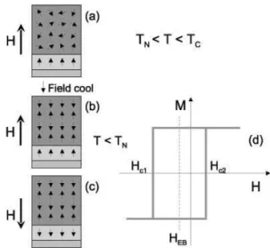
The EB effect was discovered half a century ago by Meik-lejohn and Bean when studying magnetic properties of fine Co particles that turned out to be covered by a thin oxide layer [3, 4]. About ten years ago, this phenomenon was revived and comprehensive reviews focused on many experimental [5, 6] and theoretical [7, 8] aspects were published. The basic de-scription of the EB phenomenon was given since the pioneer-ing work. For a temperature T above the AF orderpioneer-ing Nel temperature (TN) and below the FM layer Curie temperature
(TC), the AF spins are disordered while the FM are ordered
(Fig.1-a). A magnetic field H is applied in order to saturate the FM layer in a direction either parallel or perpendicular to the film surface. After cooling the AF/FM bilayer under such a magnetic field belowTN, the AF spins at the interface
couple with the FM spins (Fig.1-b), yielding the energetically stable situation for the coupling at the interface. When the
∗Electronic address:[email protected]
FIG. 1: Schematic illustration of the spin configuration of an AF/FM bilayer: a) above the AF ordering temperature TN, when the AF
spins are disordered; b) upon cooling under an applied magnetic field the AF spins close to the interface couples and align with the FM spins; c) the applied magnetic field is reversed: the FM spins fol-lows the applied field while the AF spins are not directely affected; d) scheme of the exchange bias loop shift.
magnetic field H is reversed, the AF spins exert a microscopic torque on the FM spins, tending to keep them in their original direction (Fig.1-c). The field needed to reverse the magneti-zation will be larger (|HC1|>|HC2|) and the magnetic loop
will be shifted by an amountHEB= (HC1+HC2)/2, due to
this additional interfacial magnetic energy,∆σ, that has to be
overcome (Fig.1-d).
The phenomenological expression of the exchange field is HEB=∆σ/(MFM×tFM), whereMFM andtFMare the
density, ∆σ, exceeds the experimental values by orders of
magnitude.
Many microscopic models have been proposed for the ex-pression of the total magnetic energy and, in particular, for the interface exchange energy [9–14]. Among the complex phe-nomena taking place close to the interface, domain-wall for-mation in the AF layer, random interface roughness, contribu-tion of compensated AF/FM interfaces, extension of the cou-pling beyond interfacial layers [15] and noncollinear interface spin configuration are to be considered. Moreover, the role of pinned and unpinned (AF spins that rotate) spins, or switch-able interfacial uncompensated AF spins, in the exchange bias has been recently revealed by X-ray photoemission mi-croscopy and X-ray magnetic linear and circular dichroism [16, 17]. The study of ideal systems, with atomic scale con-trol and fine characterization of the interface structure and morphology, is essential to disentangle all these parameters.
In AF materials the direction of the atomic moments varies on the length scale of nearest atomic distances. Recently, it has been shown that the magnetic coupling across the AF/FM interface in the FeMn/Co system is mediated by step edges of single-atom height [18]. The authors showed that it is possi-ble to tune the strength of the magnetic coupling among the FM layers across ultra-thin AF one and that the coupling is stronger if steps are distributed in small islands. The rea-son is that the coupling is mainly mediated by uncompen-sated spins at monoatomic step edges. This result demon-strates why roughness is so important in some EB systems. A quite different situation takes place at the Fe/NiO(001) in-terface. The concomitant expansion of the interlayer distance and the small buckling of an interfacial FeO layer lead to an increase of the spin magnetic moment of the interfacial Fe atoms, which modifies dramatically the exchange interaction [19]. The expanded interlayer distance and buckling seems to be more important to the Fe/NiO(001) AF/FM magnetic coupling than the presence of low density defective sites.
These two examples clearly demonstrate that complex sur-face interactions are the origin of EB. The electronic and mag-netic properties of these nanoscale materials are closely re-lated to the atomic arrangement at the interface shared by dif-ferent chemical elements. It is then crucial to gather a very precise knowledge of the surface/interface structure in order to understand such new coming out properties. The availabil-ity of synchrotron sources lead to a wealth of well-established tools for structural analysis of surfaces, in particular grazing incidence X-ray diffraction, scattering and absorption spec-troscopy techniques [20]. In addition, element-selective mag-netic probes, as x-ray magmag-netic circular dichroism (XMCD) and x-ray resonant magnetic scattering (XRMS), became available and complement structural and other conventional magnetic probes. Since the AF/FM interface is buried and changes in the structural and magnetic properties are small, combining all these techniques is of paramount importance to tackle the challenging description of such systems.
The major part of exchange bias studies have been per-formed with the magnetization parallel to the FM/AF inter-face. Studies on systems with perpendicular (out of plane) magnetic anisotropy (PMA) are rather recent [21–23] and only few address the role of spin configuration at the inter-face [24, 25]. We are especially interested in thin ferromag-netic films with PMA, as is the case in FePt and CoPt surface
alloys, coupled to antiferromagnets, like CoO/NiO mixed ox-ides. PMA is recognized as a way for increasing magnetic storage density. In addition, magneto optical effects are en-hancend at polar (sensitive to perpendicular magnetization component) geometry compared to in-plane one [26, 27].
We report here on a combined structural and magnetic study of the [NiO/CoO]/[PtCo] perpendicular exchange bias system. Previous experiments on a sputtered Co/Pt multi-layer with PMA coupled to a CoO oxide showed that such a system exhibits loop shifts and enhanced coercivities for both parallel and perpendicular applied magnetic fields [22]. The aim of our investigation is to obtain a fine control of the structure and to reach a comprehension of the exchange coupling mechanism at the interface of AF/FM systems that are as close as possible to model ones. Our samples have been prepared by electron beam epitaxy and oxidized in a controlled oxygen partial pressure, as described in the next section. CoO is an AF oxide with TN= 293 K and a large
magnetocrystalline anisotropy. NiO presents a much higher ordering temperature, TN= 523 K, and smaller anisotropy.
By mixing both oxides we obtained an AF material with a high magnetocrystalline anisotropy and with a Nel tempera-ture intermediate between those of the two oxides [28]. The combination of grazing incidence X-ray diffraction, X-ray re-flectivity and soft X-ray resonant magnetic scattering yields a comprehensive description of the system.
II. RESULTS AND DISCUSSION
A. Sample preparation, structure and morphology
An epitaxial [NiO(3ML)/CoO(3ML)]x3/PtCo sample was synthesized by sequential electron beam evaporation over a Pt(111) single crystal in the ultra-high vacuum (UHV) cham-ber of the French CRG BM32 beamline at ESRF [29]. The layer by layer growth described hereafter was followed step by step by in situ grazing incidence X-ray diffraction [30, 31]. The structural characteristic of the sample is then perfectly known at each stage of the growth. The very stable oxide layer on top surface enables posterior ex-situ structural, mor-phological and magnetic studies.
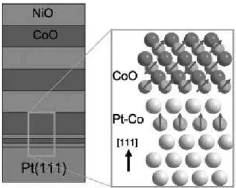
FIG. 2: Schematic sequence of the AF/FM bilayer [NiO(3ML)/CoO(3ML)]x3/PtCo sample. Insert: close view of the spin configuration at the interface CoO/PtCo, assuming that both layers are ordered and non-interacting
FIG. 3: Surface X-ray diffraction pattern during the growth of the NiO/CoO mixed oxide over the PtCo(111) surface alloy
The mixed oxide grow in orientational epitaxy on the Pt(111) substrate (Fig. 3). The first CoO atomic layer is pseudomorphe on the substrate. After the second oxide layer deposition, the layer relaxes and a bulk-like CoO(111) lattice peak shows up at K = 0.92. An hexagonal unit cell was taken for the Pt(111) crystal [32, 34]. The peak at K = 1 in the re-ciprocal space correspond to the interlayer spacing of 0.2266 nm for Pt, yielding an oxide layer in-plane interlayer spac-ing of 0.245 nm, exactly as in the CoO bulk oxide. The NiO layer grows in coherent epitaxy with the CoO and displays the same in-plane parameter, as observed by its contribution to diffraction peak intensity, at exactly the same position in the reciprocal space.
A well defined atomic stacking is observed at each step of the oxide deposition, as well as in the final sample. On the other hand, CoO diffraction rods as well posteriory ex situ measurements show that this final sample has a quite large
FIG. 4: X ray reflectivity (CuKα,λ= 0.154 nm) measurements from
the rough oxide surface. The surface has a large roughness, 1 nm, while the interface is quite flat, with roughness of about 0.1 nm.
FIG. 5: AFM of a 12 ML CoO layer grown by electron beam evapo-ration on top of a Pt(111) single crystal. A roughness close to 1 nm can be observed
rough surface. Kiessig interference fringes [20] can hardly be observed in the X-ray reflectivity profile (Fig.4). The fitting to the calculated reflectivity gives a roughness of about 1 nm at the surface, while the interface is rather flat, with roughness of about 0.1 nm. Such a large roughness is not surprinsing due to the polar character of the Pt(111) surface. AFM mea-surements in a similar oxide surface - a 12 ML CoO film on the same Pt(111) crystal surface, treated in identical condi-tions - also reveal that the surface roughness is roughly 1 nm (Fig.5).
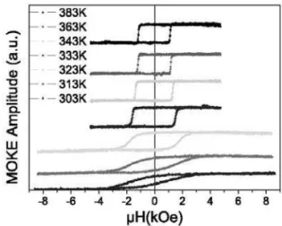
FIG. 6: PMOKE hysteresis loops measured at different tempera-tures, after field cooling from 400 K under 5 kOe.
FIG. 7: Exchange bias shift (circles-black) and coercivity (stars-red) as function of temperature. The blocking temperatureTB is
esti-mated at 320 K, close to the maximum coercivity.
B. Increased coercivity, exchange bias and spin reorientation
Magneto-optic Kerr effect (MOKE) was used to follow the magnetic properties of our sample. MOKE is a well-established technique to study magnetism in ultra-thin FM films [26]. The MOKE sub-monolayer sensitivity has been verified in many situations [27]. Polar and longitudinal MOKE are characterized by a complex rotation of the plane of polarization of the linearly polarized incident light upon reflection from the surface of a ferromagnetic material. The rotation is directly related to the magnetization of the material within the probed region of the light.
In order to induce EB, the sample was field cooled from above the Nel temperature down to room temperature un-der an applied magnetic field of 5 kOe. Then, polar MOKE (PMOKE) hysteresis loops were measured at increasing tem-peratures, up to 383 K (Fig. 6). The coercivity (HC = (HC2−HC1)/2) presents a maximum of 1.7 kOe at about 320
K, then decreases monotonically to 1.2 kOe at higher tem-peratures (Fig.7). It is worth noting that 1.2 kOe is the same value as for the PtCo surface alloy without any capping oxyde [33]. The FM layer preserves its quality and is altered just by
the exchange coupling to the AF ordered layer.
For temperatures below 320 K the hysteresis loops shifts. The temperature below which the shift appears is defined as the blocking temperature,TB= 320 K. At room temperature,
the shift is found to beHEB= -0.6 kOe and characterises the
perpendicular exchange coupling at the interface between the FM and AF layers. From that, the calculated interfacial ex-change energy is∆σ= 0.16 erg/cm2, where we used the FM
thickness astFM= 0.36 nm. This is about 2/3 of the value
found by Maat et al. [22] for a multilayer at 10 K. The most striking result in this range is that the hysteresis loops be-comes less and less squared, as indicated by the decreasing PMOKE amplitude at remanence and loop elongation (Fig. 6 and 7). The decreasing squareness of the loops indicates that the easy magnetization axis of the FM layer is no longer perpendicular. Our interpretation is that, upon field cooling, the AF spins should align along the spin anisotropy axis that is closest to the applied magnetic field [36]. This should be particularly applicable for CoO because of its high magne-tocrystalline anisotropy constant around the{117}directions. The CoO spins will be oriented along one of the{117} direc-tions, forming an angle of 43.3 with the surface normal. The orientation of the NiO magnetic moments is assumed to fol-low the CoO spins because of a strong exchange interaction at the interface [37] and a smaller magnetocrystalline anisotropy constant. Therefore, the change in the hysteresis loops is re-lated to the reorientation of the Co spins in the FM layer due to exchange coupling with the oxide layer. As far as we know, this is the first experimental observation of the reorientation of the out-of-plane interfacial FM spins induced by the order-ing of the AF layer. One should note the fact that, in other [Co/Pt]/[CoO] systems, the FM layer is thicker than a single monolayer (e.g. Maat et al [22]).
For temperatures above 320 K the hysteresis loops are squared, with a magnetization at remanence close to mag-netization at saturation. In this temperature range there is no exchange shift. The increased coercivityHCis related to the
antiferromagnetic order persisting in the mixed oxide layer. The AF ordering temperatureTNmay be estimated by the
in-flexion point of the coercivity as function of temperature [38] and turns out to beTN= 350 K. This value is smaller by 50 K
compared to the average CoO and NiO bulk Nel temperatures due to the reduced thickness effect which lowers the order temperature [36]. As can be also observed,TBis smaller by
30 K thanTN, owing to thermal activation of the AF domains.
Such kind of difference has already been pointed out by Maat et al. for the pure CoO coupled to a Co/Pt multilayer.
C. Depth profile spin configuration at the interface
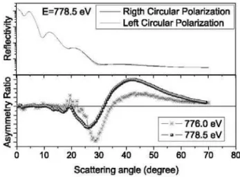
us-FIG. 8: XRMS at the CoL3edge. Upper curves correspond to the
two polarizations at E=778.5. The curves display the asymmetry ratio at two different energies about the edge.
ing the RESOXS endstation [41]. The magnetic saturation of the FM layer was achieved by a 4 kOe permanent magnet brought to the sample perpendicularly to its surface.
The measurements were carried out in remanence at T = 340 K, right aboveTB and belowTN, where the FM layer
has a strong PMA and where the interfacial magnetic cou-pling with the AF layer constrains the reversal process, as in-dicated by the increasedHC (Fig. 7). The reflected intensity
was recorded as a function of the scattering angle at different photon energies, and as function of energy at fixed scatter-ing settscatter-ings. The asymmetry ratios, or normalized dichroic differences, were measured using 98% left and right circu-larly polarized beam [42]. Absorption spectra were collected simultaneously by recording the drain current as a function of incident photon energy. The spectral shape of the absorp-tion is essentially that of the CoO and NiO oxide, as expected from a total electron yield measurement[43]. In reflectivity condition, the penetration depth is large enough to probe the buried Co layer.
Angle dependent reflected intensity (Fig. 8-a) were col-lected at 776.9 and 778.5 eV close to the CoL3 edge. At
both energies, a separation of the curves with right and left polarized ligth is observed. The asymmetry ratios at both en-ergies are close to zero at small angles and exhibit a larger amplitude at high angles (Fig. 8-b), in agreement with the ge-ometrical dependence of the atomic scattering factor arising from an out-of-plane magnetization component. This angle dependence is mainly due to the Co magnetization in the Pt-Co layer and in the oxide layer.
The structural parameters of the film were derived from the the refinement of the average reflectivity. The total thick-nesses is about 5.45 nm of oxide and 0.36 nm of PtCo. This is in good agreement with the expected thickness from the se-quential deposition of 18 ML of oxide and 1ML of Co. The roughnesses are 0.02 and 0.9 nm for the interface CoO/PtCo and for the top NiO/CoO interfaces, respectively, is in agree-ment the X-ray reflectivity and AFM results, too.
The magnetic profile comes from the analysis of the asym-metry ratio at both energies. The interference at about 32 indi-cates a magnetic thickness smaller than the total oxide thick-ness. A model assuming that Co atoms in the oxide may be
magnetically ordered up to the first CoO/NiO interface works well. The refinement of the magnetic structure was performed by dividing the first CoO layer in three slices and by adjust-ing their thicknesses as well as the magnetic moments carried by the Co atoms. The results indicate the out-of-plane mag-netization is distributed beyond the 0.36 nm Pt-Co layer and extends over 1 nm in the oxide layer. The coupling to the FM Co spins is parallel in a 0.3 nm thick slice, roughly the first CoO monolayer.Then, it is antiparallel in a 0.7 nm thick one, with similar amplitude. The last slice that completes the CoO layer is found to be 0.2 nm thick and has no net magnetiza-tion. Considering models with no magnetization in the oxide layer, completely parallel or antiparallel magnetic slices and more extended magnetization with reduced magnetic ampli-tude do not fit the interference effect observed experimentally. This result can be understood as follows: the Co atoms in the first CoO slice, right on top of the Pt-Co layer, have a mixed electronic character in between metallic and oxidized state. Their net induced magnetization are likely to be dominated by the proximity of the Pt-Co layer and are ferromagnetically coupled to it. For the next CoO slice, the Co atoms are fully oxidized and the net magnetization is antiferromagnetically coupled to the first one. The net magnetization found equal to zero in the third slice means that beyond the second oxide layer the AF material break into domains that are not biased by the field cooling processes.
III. SUMMARY
Our results show that valuable insights into the surface structure and magnetism in the CoO/PtCo system emerge from combination of in situ, ex situ, and in-depth sensitive structural and magnetic characterizations. In situ grazing in-cidence X-ray diffraction (GIXRD) results demonstrate that the AF oxide grows epitaxially on top of the PtCo(111) sur-face alloy. The top sursur-face of the mixed oxide is rough while the interface CoO/PtCo is quite flat over the whole crystal. The perpendicular magnetic anisotropy, well above the Nel temperature, is the same as for the uncapped PtCo layer, showing that the quality of the layer is preserved after oxide deposition. Upon field cooling, slightly aboveTB, the ultra
thin Co ferromagnetic layer exhibits a strong perpendicular anisotropy and magnetic ordering is induced over a few oxide atomic layers. The out-of-plane magnetic profile shows that oxidized Co atoms closest to the interface are ferromagnet-ically coupled to the PtCo ferromagnetic layer. The second oxide layer then couples to this interfacial one antiferromag-netically. Below the blocking temperatureTB, MOKE
indi-cates a spin reorientation in the FM layer that would follow the blocked Co spins of the AF layers. Such reorientation in that FM surface layer indicates that the interfacial spins in a thicker FM layer is strongly modified by the ordering of the top AF layer.
Aknowledgements
N´eel, CNRS, France) is also acknowledge for helping during MOKE measurements.
[1] M. N. Baibich, J. M. Broto, A. Fert, F. N. Van Dau, F. Petroff, P. Eitenne, G. Creuzet, A. Friederich, and J. Chazelas, Phys. Rev. Lett.61, 2472 (1988).
[2] S. Parkin, K. Roche, M. Samant, P. Rice, R. Beyers, R. Scheuerlein, E. OSullivan, S. Brown, J. Bucchigano, D. Abraham, et al., J. Appl. Phys.85, 5828 (1999).
[3] W. H. Meiklejohn and C. P. Bean, Phys. Rev.102, 1413 (1956). [4] W. H. Meiklejohn and C. P. Bean, Phys. Rev.105, 904 (1957). [5] J. Nogues and I. K. Schuller, J. Magn. Magn. Mater.192, 203
(1999).
[6] A. E. Berkowitz and K. Takano, J. Magn. Magn. Mater.200, 552 (1999).
[7] M. Kiwi, J.Mag.Mag.Mat.234, 584 (2001). [8] R. Stamps, J.Phys.D:Appl.Phys.33, R247 (2000).
[9] D. Mauri, H. Siegmann, P. Bagus, and E. Kay, J. Appl. Phys.
62, 3047 (1987).
[10] A. P. Malozemoff, Phys. Rev. B35, 3679 (1987). [11] N. C. Koon, Phys. Rev. Lett.78, 4865 (1997).
[12] M. D. Stiles and R. D. McMichael, Phys. Rev. B59, 3722 (1999).
[13] U. Nowak, K. D. Usadel, J. Keller, P. Milt´enyi, B. Beschoten, and G. G¨untherodt, Phys. Rev. B66, 014430 (2002).
[14] K. Lee, Y. Yu, and S. Kim, Appl. Phys. Lett.86, 192512 (2005). [15] J. Kortright, D. Awschalom, J. Stohr, S. Bader, Y. Idzerda, S. Parkin, I. Schuller, and H. Siegmann, J.Mag.Mag.Mat.207, 7 (1999).
[16] H. Ohldag, T. J. Regan, J. St¨ohr, A. Scholl, F. Nolting, J. L¨uning, C. Stamm, S. Anders, and R. L. White, Phys. Rev. Lett.87, 247201 (2001).
[17] H. Ohldag, A. Scholl, F. Nolting, E. Arenholz, S. Maat, A. T. Young, M. Carey, and J. St¨ohr, Phys. Rev. Lett.91, 017203 (2003).
[18] W. Kuch, L. Chelaru, F. Offi, J. Wang, M. Kotsugi, and J. Kirschner, Nature Materials5, 128 (2006).
[19] P. Luches, V. Bellini, S. Colonna, L. D. Giustino, F. Manghi, S. Valeri, and F. Boscherini, Physical Review Letters 96, 106106 (pages 4) (2006).
[20] A. Nielsen,An Introduction to X-Ray Physics(Elsevier Sci-ence, 2000).
[21] B. Kagerer, C. Binek, and W. Kleemann, J. Magn. Magn. Mater.217, 139 (2000).
[22] S. Maat, K. Takano, S. S. P. Parkin, and E. E. Fullerton, Phys. Rev. Lett.87, 087202 (2001).
[23] J. Sort, V. Baltz, F. Garcia, B. Rodmacq, and B. Dieny, Phys-ical Review B (Condensed Matter and Materials Physics)71, 054411 (pages 7) (2005).
[24] S. M. Zhou, L. Sun, P. C. Searson, and C. L. Chien, Phys. Rev. B69, 024408 (pages 5) (2004).
[25] A. Baruth, D. J. Keavney, J. D. Burton, K. Janicka, E. Y. Tsym-bal, L. Yuan, S. H. Liou, and S. Adenwalla, Phys. Rev. B74, 054419 (pages 13) (2006).
[26] S. Bader, J.Mag.Mag.Mat.100, 440 (1991).
[27] Z. Qiu and S. Bader, J.Mag.Mag.Mat.200, 664 (1999). [28] J. A. Borchers, M. J. Carey, R. W. Erwin, C. F. Majkrzak, and
A. E. Berkowitz, Phys. Rev. Lett.70, 1878 (1993).
[29] R. Baudoing-Savois, M. De Santis, M. Saint-Lager, P. Dolle, O. Geaymond, P. Taunier, P. Jeantet, J. Roux, G. Renaud, A. Barbier, et al., Nucl. Instrum. and Meth. in Phys. Res. B
149, 213 (1999).
[30] E. Vlieg, J. F. Van Der Veen, S. J. Gurman, C. Norris, and J. E. Macdonald, Surface Science210, 301 (1989).
[31] I. K. Robinson, Handbook of Synchrotron Radiation, vol. 3 (North Holland - Amsterdam, 1991).
[32] M. De Santis, R. Baudoing-Savois, P. Dolle, and M. C. Saint-Lager, Phys. Rev. B66, 085412 (2002).
[33] L. Giovanelli, M. De Santis, G. Panaccione, F. Sirotti, P. Torelli, I. Vobornik, R. Larcipretea, S. Egger, M. Saint-Lager, P. Dolle, et al., J. Magn. Magn. Mater.288, 236 (2005). [34] B. E. Waren, X-Ray Diffraction (Dover Publications - New
York, 1994).
[35] N. Berdunov, G. Mariotto, K. Balakrishnan, S. Murphy, and I. V. Shvets, Surface Science600, L287 (2006).
[36] D. Alders, L. H. Tjeng, F. C. Voogt, T. Hibma, G. A. Sawatzky, C. T. Chen, J. Vogel, M. Sacchi, and S. Iacobucci, Phys. Rev. B57, 11623 (1998).
[37] M. J. Carey and A. E. Berkowitz (AIP, 1993), vol. 73, pp. 6892–6897.
[38] K. Lenz, S. Zander, and W. Kuch, Physical Review Letters98, 237201 (pages 4) (2007).
[39] J. M. Tonnerre, L. S`eve, D. Raoux, G. Soulli´e, B. Rodmacq, and P. Wolfers, Phys. Rev. Lett.75, 740 (1995).
[40] J. P. Hill and D. F. McMorrow, Acta Crystallographica Section A52, 236 (1996).
[41] N. Jaouen, J.-M. Tonnerre, G. Kapoujian, P. Taunier, J.-P. Roux, D. Raoux, and F. Sirotti, Journal of Synchrotron Radia-tion11, 353 (2004).
[42] J. M. Tonnerre, M. D. Santis, S. Grenier, H. C. N. Tolentino, V. Langlais, E. Bontempi, M. Garc´ıa-Fern´andez, and U. Staub, Physical Review Letters100, 157202 (pages 4) (2008). [43] T. J. Regan, H. Ohldag, C. Stamm, F. Nolting, J. L¨uning,