Article
J. Braz. Chem. Soc., Vol. 26, No. 5, 992-1003, 2015.Printed in Brazil - ©2015 Sociedade Brasileira de Química 0103 - 5053 $6.00+0.00
A
*e-mail: [email protected]
New Flexible and Transparent Solution-Based Germanium-Sulfide
Polymeric Materials
Denise T. B. De Salvi,*,a Aldo E. Jobb and Sidney J. L. Ribeiroa
aInstituto de Química, Universidade Estadual Paulista, CP 355, 14801-970 Araraquara-SP, Brazil
bLaboratório de Química Orgânica Fina, Departamento de Física, Química e Biologia,
Universidade Estadual Paulista, Campus de Presidente Prudente, CP 467, 19060-900 Presidente Prudente-SP, Brazil
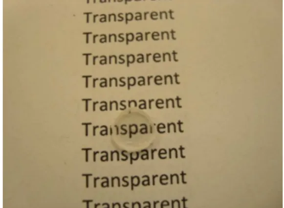
New flexible and transparent materials based on germanium sulfide were obtained using GeCl4 and 1,3-propanedithiol as precursors. These materials have transparency in the ultraviolet-visible (UV-Vis) spectral region (about 70%), thermal stability up to 200 °C and glass transition located at temperatures below 0 °C (−37 °C, −56 °C and −59 °C) as shown by differential scanning calorimetry (DSC) curves. Scanning electron microscopy (SEM) images showed that the polymer is homogeneous and presents formation of crystals in some regions of the surface. These polymers also exhibit Ge−S bonds in its structure, as can be observed through Fourier transform infrared (FTIR) (bands at 399, 401, 432 and 470 cm-1) and Raman (peaks at 361 and 430 cm-1) spectroscopies, and the diffraction patterns X-rays, which suggest the formation of a mixture of GeS2 and GeO2 phases (also confirmed through energy-dispersive X-ray analysis). The coupled thermogravimetric analysis / Fourier transform infrared (TG/FTIR) technique was used to investigate the degradation of the sample. Taken together, the results of these characterizations suggest optical applications, and usability at low temperatures.
Keywords: germanium sulfide, polymer, solution-based, transparent
Introduction
Chalcogenide glasses are materials in which sulfur,
selenium, or tellurium form one of the basic constituents.1
They exhibit interesting properties, such as large transparency window in the mid-infrared spectral range and large refractive indices (in comparison to oxide counterparts). Applications in photonic sensors, photo-induced phenomena, integrated optics, trace gas sensors (to detect greenhouse gases) and other optical devices can
be found in lterature.2,3 Germanium sulfides in particular
are interesting since they also present amazing electronic and optical properties. Hologram recording media, optical coatings, fiber optics, solid-electrolyte lithium batteries and semiconductors are some of the reported potential
applications for them.4
Photo-induced effects are observed for GeS binary
glasses irradiated by 800 nm femtosecond pulses5 or
in Ge25Ga10S65 glasses.
6 Grillanda et al.7 exploited the
high photosensitivity of As2S3 glasses to the wavelength
range of visible light irradiation for inducing variations in their refractive index and in the optical properties of
chalcogenide-based devices. Photosensitivity of As2S3
glasses was also investigated by Shtutina et al.:8 they
studied photoinduced processes in vitreous films of As2S3.
These effects allow the utilization of these materials as
potential optical recording media.9
Normally these glasses are obtained by classic melting-quenching methods or evaporation in the case
of thin films.1,10 However one simple way to obtain these
glasses and other related materials involves the so-called sol-gel methodology, where basically liquid precursors are used in order to obtain a solid. Low temperature, solutions processing and high purity of precursors are well known characteristics of that methodology that typically lead to homogeneous products with high purity. As the precursors are mixed at the molecular level, it is relatively easy to obtain a product with controlled structure and
stoichiometry.11-13
Xu and Almeida14 have prepared glassy films and optical
planar waveguides based on germanium sulfide through the
the H2S through the GeCl4 or GeCl4 + SbCl3 dissolved in toluene in the presence of propionic acid as a catalyst). The
preparation of GeS2 and Er3+ doped GeS2 gels from Ge(OEt)4,
ErCl3 and H2S precursors was reported by Aggarwal and
co-workers.15 An sol-gel approach is also described by
Seddon et al.16 for germanium disulphide formation through
dihydrogen sulphide treatment of germanium tetra-ethoxide. Aerogels may also be obtained. Aerogels composed of semiconducting metal chalcogenide (S, Se, Te), such as
CuInS2, In2S3, CuInSe2 and CuGaSe2 exhibit electronic and
optical properties very useful in photovoltaic cells and light
emiting diodes are described.17
Optical materials are an important research field and optics and astronomy guided the development of a wide range of glass compositions in the last 300 years. Infrared optical technology (which involves optical communication, military and defense applications, nightly vision and thermo-vision systems) also has been increasing its demand for new optical materials.
Recently, advances in chemistry turned possible to obtain polymers with low light scattering, which should become an alternative to the inorganic glasses once they present some advantages, e.g., low weight, ease of processing and molding, mechanical toughness, cheapness and simple chemical variation through the employment of commercially available precursors. Some of these polymers
are being used in visible imaging.18 The development of
organic-based polymers are an alternative to the use of inorganic metal oxide, semiconductor, or chalcogenide-based materials in optical devices and components like waveguides, anti-reflective coatings, charge-coupled devices and fiber optic cables. In the case of chalcogenide materials, efforts are being done in order to obtain polymers with germanium and sulfur in their structure.
The preparation of a germanium-containing copolymer having a germanium (IV) unit and a trimethylene sulfide unit alternatingly in the main chain was described by
Shoda et al.19 The copolymer was obtained through the
use of a germylene (1,3-bis(trimethylsilyl)-1,3-diaza-2-germa(II)-indan) and thietane. Polymeric metal thiolates are new polymers and have potentially utilities as functional materials due to their characteristic structure
including a Ge−S−C moiety in the main chain. The paper
of Shoda et al.19 describes the synthesis of a
germanium-containing polymer which presents a germanium thiolate
unit (−Ge−SCH
2CH2CH2−) in the main chain. Their
synthesis involves ring-opening copolymerization of a divalent germanium compound with thietane. Other
example is presented by Nellis et al.20 who synthesized
a one-dimensional germanium sulfide polymer through hydrothermal recrystallization of simple metal oxide and
sulfide precursors in the presence of organic amines. Due to their regular array of pores and channels, these materials can be used as molecular sieves, ion exchangers and catalysts.
Inverse vulcanization is a process capable of stabilizing polymeric sulfur through copolymerization of a large excess of sulfur with a modest amount of small-molecule dienes. It differs from the conventional vulcanization, where polydienes are crosslinked with a low amount of sulfur in order to form synthetic rubber. Sulfur possesses a number of interesting properties, e.g., high electrochemical capacities and high refractive indices. Examples of sulfur copolymers synthesized through inverse vulcanization from elemental sulfur and 1,3-diisopropenylbenzene (DIB) are those
presented by Namnabat et al.21 (the moldable and transparent
materials obtained by them present potential use in the
mid-infrared at 3-5 microns), Chung et al.22 (these new materials
presented electrochemical properties and they could be used
as the active material in Li−S batteries) and Griebel et al.23
(they obtained a thermoplastic copolymer with a high
content of S−S bonds (50-80%) for infrared optics). These
are examples of new materials obtained from an alternative chemical feedstock with possible applications in bulk optics, high-density photonic circuits, and infrared components.
In this work, the preparation and characterization of new solution - based germanium-sulphide polymers - is described by using germanium (IV) chloride and 1,3-propanedithiol as precursors. Characterization of the new materials was performed by ultraviolet-visible (UV-Vis) absorption and UV-Vis diffuse reflectance, scanning electron microscopy (SEM), energy dispersive X-ray spectroscopy (EDS), X-ray diffraction (XRD), Fourier transform infrared spectroscopy (FTIR), Raman scattering, thermogravimetric analysis coupled to Fourier transform infrared (TG/FTIR) and differential scanning calorimetry (DSC).
Experimental
Materials
All reagents were of analytical grade. Germanium (IV) chloride (99.9999%) was purchased from Alfa-Aesar and 1,3-propanedithiol (99%) was purchased from Sigma-Aldrich.
Sample preparation
Solutions were obtained by mixing appropriate amounts
of germanium (IV) chloride and 1,3-propanedithiol. GeCl4
were obtained and submitted to thermal treatment (a heating program where the samples were kept, involving 1 h at 50 °C, 1 h at 120° and 2 h at 200 °C). Samples were named Geprop 1, Geprop 2 and Geprop 3 for simplicity purposes.
Characterization
The UV-Vis transmission spectrum was recorded on a Perkin Elmer Lambda 1050 UV/VIS/NIR double beam spectrophotometer. The UV-Vis diffuse reflectance spectrum was obtained in a Varian Cary 500 UV-Vis spectrometer in 200-800 nm range using high-purity MgO as spectroscopic standard.
Scanning electron microscopic (SEM) images and energy dispersive X-ray spectroscopy analysis (EDS) were taken in a field emission scanning electron microscope (FESEM, JEOL JSM - 7500F). A thin film of carbon was sputtered onto the surface of the sample.
XRD measurements were performed on a Siemens Kristalloflex X-ray diffractometer in steps of 0.01° using
Cu Kα radiation as X-ray source.
Fourier transform infrared (FTIR) spectra were obtained with a Perkin-Elmer spectrometer, model Frontier. The samples were milled and mixed with dried KBr (for
4000-330 cm-1 range) or CsI (for 700-200 cm-1 range) and
pressed into pellets. Attenuated total reflectance (ATR) spectra were obtained in a Bruker Vertex 70 FTIR.
Raman spectroscopy was performed using a Raman Horiba Jobin-Yvon model LabRAM HR 800 spectrometer, operating with laser He-Ne 632.81 nm with a CCD camera model DU420A-OE-325.
Thermogravimetric curves (TG) were obtained for dried samples in a TG/FTIR system (all gas evaporated in the TG chamber is channeled to the FTIR spectrometer) where the equipment used was Netzsch (model 209). FTIR spectra
was recorded in the wavenumber range 4000-500 cm-1 with
4 cm-1 of spectral resolution, 32 scans, and a deuterated
triglycine sulfate (DTGS) detector. Samples (5.0 mg)
were heated in an alumina crucible using N2 as gas carrier
(15 mL min-1) and a heating rate of 10 °C min-1.
The differential scanning calorimetric (DSC) measurements were performed using a Netzsch DSC Pegasus 404F3 (Netzsch GmbH, Selb, Germany) apparatus.
Samples were heated into sealed Al pans using N2 as gas
carrier at flow rate of 80 mL min-1 and heating rate of
20 °C min-1.
Results and Discussion
All samples obtained exhibited transparency and flexibility.
UV-Vis / optical properties
Figure 1 shows the optical transmission spectra of the selected sample Geprop 1. The spectrum show that the normalized transmittance results of the sample is reasonably high in the visible range. The transmittance values exhibited in 555 nm for Geprop 1 is 73% (1 mm thickness). This wavelength corresponds to the maximum
sensitivity of the human eye.24 The UV diffuse reflectance
spectrum of Geprop 1 is presented in Figure 2b. From this spectrum, we can estimate the absorption edge (344 nm) and the bandgap energy (3.60 eV).
SEM images
The morphology of the Geprop 1 sample prepared by a solution-based method were investigated by SEM. The surface of the sample is homogeneous and fairly smooth, with no observed porosity, as seen in Figures 3a and 3b.
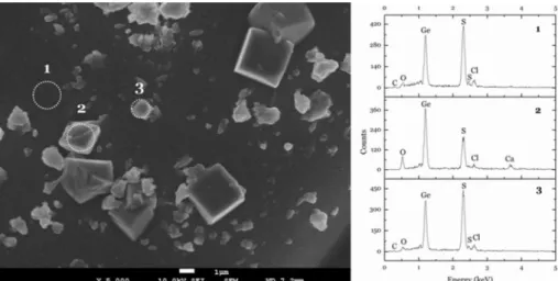
The observation of the surface revealed the growth of crystals in some regions, as seen in Figure 4, left. During the heat treatment, the solution becomes more saturated (due to HCl elimination, which is released in the reaction
of GeCl4 with 1,3-propanedithiol) and, in contact with air,
crystals are formed in some regions of the surface. EDS analysis was conducted in order to estimate the composition of these crystals. Three selected regions of the image shown in Figure 4 (left), were analized and the respectives EDS spectra are shown in Figure 4 (right). The analysis of region 1, corresponding to the polymer, showed small amount of carbon (from the coating), oxygen and chlorine. Germanium and sulfur are detected in higher amount, possibly corresponding to the polymeric phase of the sample. The EDS analysis of regions 2 and 3, which correspond to the crystals observed, are shown in Figure 4 (right). C, O and Cl were also observed (Ca is seen in spectrum 2 due to contamination). Ge, O and S were
detected in the EDS analysis of the crystals, suggesting that these crystals are GeS2 and/or GeO2.
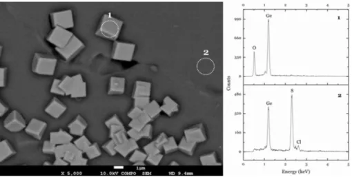
Backscattered electron image of a selected region of the Geprop 1 surface is shown in Figure 5 (left). This kind of
image is useful to observe the contrast in areas that present different chemical compositions - in the image, it is possible to observe the difference between the crystals formed in the surface (brighter region), and the polymer (darker region) phases. EDS analysis of these two different regions is shown in Figure 5 (right). Spectrum of region 1 (crystal) presented lines regarded to Ge and O, suggesting these crystals could be GeO2. In the region 2, the elements observed are Ge, S and
Cl, which correspond to the polymer phase of the sample. Figures 6a and 6b show the image of a fracture region of the Geprop 1. Crystals and pores are not observed in this region, corroborating the suggestion that crystals observed in Figures 4 and 5 are formed only on the surface of the samples.
200 300 400 500 600 700 800
0 10 20 30 40 50 60 70 80 90 100
N
o
rm
a
liz
e
d
tr
a
n
s
m
it
ta
n
c
e
/
%
Wavelength / nm
(a)
200 300 400 500 600 700 800
0 10 20 30 40 50 60 70 80 90 100
R
e
fl
e
c
ta
n
c
e
/
%
Wavelength / nm
(b)
Figure 2. Normal transmittance (a) and diffuse reflectance (b) of the sample Geprop 1.
Figure 3. SEM images of Geprop 1 surface, (a) 20,000× and (b) 50,000×.
XRD
Figure 7 shows normalized XRD diffraction patterns of (a) GeS2, (b) GeO2, and Geprop samples (c, d, and e). The
diffractograms of the Geprop samples present sharp peaks between 5 and 80° and an amorphous one at 2θ = 15°. These
peaks are characteristic of GeS2 and GeO2.
The sharp and intense diffraction peak observed around 2θ = 15° for crystalline GeS
2, Figure 7a, (referred to
tetragonal and orthorrombic phases of GeS2) is seen as a
broadened and low intensity peak in 7c, 7d and 7e, which suggests formation of GeS2 nanocrystals.25
Figure 7b presents GeO2 diffraction pattern. The peaks
at 20 and 25° (more intense) and those at 35, 37, 39, 42, 48, 53, 58, 62, 66, 69, 73 and 77° (less intense), regarded to GeO2, are observed in XRD diffraction patterns of
Geprop 3, Figure 7e. Also, Figures 7d and 7e present some peaks referred to GeO2. Existence of more peaks assigned
to GeO2, seen in Figure 7e, is most probably due to the
higher Ge relative content. Since the heat treatment was conducted inside a furnace without controlled atmosphere, the formation of GeO2 could be favored.26
As Geprop samples diffractograms present both GeS2
and GeO2 XRD patterns, one can suggest the formation of
a mixture of GeS2 and GeO2 phase within these samples.
FTIR
Figure 8 shows FTIR spectra for Geprop samples in 4000-330 cm-1 (left) and 700-200 cm-1 (right) regions. The
Geprop samples exhibited similar vibration characteristics in their FTIR spectra. These spectra present symmetric and asymmetric stretching of CH2 (2956, 2929, 2917
and 2836 cm-1), C−S (741, 709, 670, 638 and 612 cm-1)
and S−S (473 cm-1) vibration groups. Bending of CH 2,
CSC, CCS and SH are also observed, arising from the following groups −CH
2−S− , −CH2−SH and –(CH2)n−. 27
Monoclinic GeS2 is confirmed by vibration bands 399,
401, 432 and 470 cm-1 (Figure 8e, left).11 The polymer has
a strong absorption peak at ca. 850 cm-1, which is referred
to asymmetric stretching of Ge−O−Ge and confirms the
presence of hexagonal GeO2 (Figure 8d, left).11,16 Stretching
and bending of OH is probably seen due to adsorbed water.
RAMAN
The Raman spectra for (a) Geprop 1, (b) Geprop 2 and (c) Geprop 3 and the reference samples (d) GeO2, (e) GeS2,
(f) Sn and (g) Ge are shown in Figure 9 in the 4000-100 cm-1
(left) and 700-100 cm-1 (right) frequency ranges. Figure 5. Backscattered electron image (5,000×) of Geprop 1 surface (left) and EDS analysis of points 1 and 2 (right).
Figure 9a-c present symmetric and asymmetric stretching of CH2 (2840, 2914 and 2960 cm
-1) and CS (612,
705 and 760 cm-1) vibration groups, together with bending
of CH2 (710 and 757 cm
-1), CSC and CCS (284, 305,
361 and 395 cm-1) and SH (669 cm-1), arising from the
following groups −CH
2−S− and −(CH2)n−
27 The SH band,
near 2500 cm-1, is absent.
Figure 9 also presents the Raman spectra of GeO2, GeS2,
S and Ge for comparative purposes. The Raman spectrum of GeO2 powder is presented in Figure 9d. The observed
frequency bands are characteristic of alpha-quartz like GeO2: 121, 164, 210, 261, 327, 514 and 592 cm
-1.28 The
164 cm-1 is present at Raman spectrum of Geprop samples
(Figure 9a-c), which also suggests the presence of Ge−O
bonds in these polymers.
Figure 9e presents the Raman spectrum of GeS2
powder. The main bands observed are related to the four distinct vibrations of XY4 tetrahedral molecules: 115 cm
-1
(symmetrical bending), 149 cm-1 (asymmetrical bending),
344 cm-1 (regarded to symmetrical stretching vibration),
while the 408 cm-1 band is related to asymmetrical
stretching. Two additional bands arise from the two
different ways of connecting the GeS4 tetrahedra: the
429 cm-1 band is related to the vibration of two tetrahedra
that are connected through bridging sulfur at the corner and the 376 cm-1 is a companion band regarded to the
vibration of two edge-shared tetrahedra.29 The bands 149,
359, 429 and 434 cm-1 are seen in the Raman spectra of
Geprop samples (Figures 9a-c), which corroborates the observation that these polymers present Ge−S bonds within
their structure.
The Raman bands of sulfur powder are shown in Figure 9f: 150, 217, 246, 437 and 471 cm-1.30,31 The bands
150 and 437 cm-1 are also present in the Raman spectrum
of Geprop samples (Figures 9a-c), suggesting the presence of S−S bonds.
Raman spectrum of metallic germanium is shown in Figure 9g. Only one peak is seen at 298 cm-1, which
corresponds to the Ge−Ge mode.32,33 This frequency
is not observed in the Raman spectra of Geprop samples (Figure 9a-c) suggesting the absence of Ge−Ge
bonds.
The frequencies attributed to Ge−S bonds are also
observed at 361 and at 430 cm-1 (Figure 9a-c) that arise
from the connections between the GeS4 tetrahedra
and short S−S bonds between these tetrahedra.29,34
Mateleshko et al.35 studied GeS
2 glasses and films and
attribute the bands at 430 and 368 cm-1 to edge-shared
tetrahedra (a band at 340 cm-1 should be attributed to
corner-shared tetrahedra). A small peak at 410 cm-1
may be attributed to symmetric stretching of Ge−O−Ge
bridging bonds or, as suggested in recent studies, the band between 360 and 400 cm-1 may be attributed to mixed
oxysulphide species (GeS3/2O1/2, GeS2/2O2/2 and GeS1/2O3/2),
with Ge−S−Ge and Ge−O−Ge bridging bonds. Bending
modes of S−Ge−O bonds can be observed at 270 cm-1.36
All these frequencies confirm the formation of Ge−S
bonds, as long as the presence of GeO2 (also observed in
XRD patterns of Geprop samples, Figure 7, and in FTIR spectra, shown in Figure 8).
TG/FTIR
TG and derivative thermogravimetric analysis (DTG) curves are presented in Figure 10. Temperature values (Tonset) are shown in Figure 10 for each DTG peak.
Three main events are observed, except for Geprop 1 (Figure 10a). With the increase in the Ge content this broad event splits in two well defined events. For the sample Geprop 2 (Figure 10b) the events occur at 286 and 336 oC.
For the highest Ge content (Geprop 3, Figure 10c) they occur at 226 and 332 oC. The third event occurs at around
720 oC for the 3 samples.
10 15 20 25 30 35 40 45 50 55 60 65 70 75 80
10 15 20 25 30 35 40 45 50 55 60 65 70 75 80 (e) Geprop 3
(d) Geprop 2
(c) Geprop 1
(b) GeO2
(a) GeS2
2 / degreeθ
Intensity / a.u.
Figure 7. XRD patterns. (a) GeS2; (b) GeO2; (c) Geprop 1; (d) Geprop 2;
Figure 8. FTIR spectra of (a) Geprop 1, (b) Geprop 2, (c) Geprop 3, (d) GeO2, (e) GeS2 in the 4000-330 cm
-1 (left) and 700-200 cm-1 (right) frequency ranges.
4000 3500 3000 2500 2000 1500 1000 500
4000 3500 3000 2500 2000 1500 1000 500
Wavenumber / cm-1
Intensit
y
/
a
.u
.
(e) GeS2
(d) GeO2
(c) Geprop 3
(b) Geprop 2
(a) Geprop 1
700 600 500 400 300 200
700 600 500 400 300 200
Geprop 3
Geprop 2
Wavenumber / cm-1 Geprop 1
In
te
n
s
it
y
/
a
.u
.
Figure 9. Raman scattering of (a) Geprop 1, (b) Geprop 2, (c) Geprop 3, (d) GeO2, (e) GeS2, (f) Sn and (g) Ge, in the 4000-100 cm
-1 (left) and
700-100 cm-1 (right) frequency ranges.
500 1000 1500 2000 2500 3000 3500 4000
500 1000 1500 2000 2500 3000 3500 4000
Raman shift / cm-1
(a) Geprop 1 (b) Geprop 2 (c) Geprop 3
Intensit
y
/
a
.u
.
(d) GeO2 (e) GeS2 (f) Sn (g) Ge
100 200 300 400 500 600 700
100 200 300 400 500 600 700
Raman shift / cm-1
(a) Geprop 1 (b) Geprop 2 (c) Geprop 3
Intensit
y
/
a
.u
.
Geprop 1, Figure 10a, shows a higher mass loss in the first step (52%), followed by gradually lower mass losses in the second and third steps (24% and 18%, respectively). The other samples also present three degradation steps. For Geprop 2, Figure 10b, the mass losses observed are 38%, 42% and 15%, and for Geprop 3, Figure 10c, these values are 49%, 33% and 11%.
The Tonset of Geprop samples are seen to slightly shift
to lower temperatures, as observed for Geprop 1 (300 °C, 340 °C and 727 °C) and Geprop 3 samples (226 °C, 332 °C and 703 °C). This decrease of the Tonset may be explained in
terms of the gradual increase in germanium content in the samples Geprop 2 and Geprop 3, which causes instability in the polymeric chain and diminish the thermal stability of those samples which present a higher germanium content (Geprop 2 and Geprop 3).
For sulfide polymers, elimination of –CH2SH and
−CH=S end groups is observed, probably originated from
thermal cleavage reactions involving a series of homolytic chain scissions followed by hydrogen transfer reactions. Sulfur is also eliminated as H2S. The low amount of residue
left at high temperatures (residue for these samples are seen to be in the 5-6% range) may indicate the absence of formation of cross-linked and condensed structures during the pyrolysis process, suggesting that the polymer chain is not hyper-branched.37
In order to estimate the composition of the residue, FTIR and Raman spectroscopy (Figure 11) were employed to analyze Geprop 1 samples thermally treated for 2 h in the selected temperatures 400 °C, 800 °C and 900 °C (Figures 11b-d, respectively). GeO2 and GeS2
spectra are also shown for comparison purposes in Figures 11e and 11f.
It could be observed that the thermal treatment favors the gradual formation of germanium oxide as temperature increases up to 900 °C when observing the FTIR and Raman spectra of the samples.
The intense peak around 410 cm-1 seen in the FTIR
spectrum (Figure 11a, left) and the 367 cm-1 peak seen
in the Raman spectrum (Figure 11a, right) are referred to GeS2 present in the Geprop 1 sample (shown in
Figure 11f). These peaks are seen to diminish and/or disappear in the 400 °C, 800 °C and 900 °C FTIR and Raman spectra (Figures 11b-d, left and right), to the detriment of the appearance of new Raman peaks 121 cm-1, 165 cm-1 and 441 cm-1 relating to the GeO
2
(Figure 11e, right).
The 547 cm-1 and 852 cm-1 FTIR bands are seen for
Geprop 1 (Figure 11a, left) and are attributed to GeO2. These
bands appear gradually broadened in the FTIR spectra of the thermally treated samples (Figures 11b-d, left).
In addition, there is a wide similarity between the FTIR and Raman spectra of the sample thermally treated at 900 °C (Figure 11d) and the GeO2 sample (Figure 11e).
As the most intense peaks observed in Figure 11d are those regarded to GeO2, this should corroborate the
suggestion that the composition of the residue in the temperature of 900 °C is composed, at mostly, of GeO2.
The vapor phase evolved during decomposition (under an inert atmosphere of nitrogen) of the samples was monitored using a thermogravimetric coupled-FTIR
100 200 300 400 500 600 700 800 900
0 20 40 60 80 100 727 °C
Temperature / °C
W
eight / %
W
eight / %
W
eight / %
340 °C -1.2 -1.0 -0.8 -0.6 -0.4 -0.2 0.0 0.2 52%
DTG / (%/°C)
DTG / (%/°C)
DTG / (%/°C)
(a) Geprop 1
24%
18% 300 °C
100 200 300 400 500 600 700 800 900
0 20 40 60 80 100 703 °C 332 °C 226 °C
Temperature / °C
(c) Geprop 3
49% 33% 11% -0.8 -0.6 -0.4 -0.2 0.0
100 200 300 400 500 600 700 800 900
0 20 40 60 80 100 727 °C 336 °C 286 °C
Temperature / °C
(b) Geprop 2
38% 42% 15% -1.4 -1.2 -1.0 -0.8 -0.6 -0.4 -0.2 0.0 0.2
Figure 10. TG/DTG curves of (a) Geprop 1, (b) Geprop 2 and (c) Geprop 3.
100 200 300 400 500 600 700 800 900
0 20 40 60 80 100 727 °C
Temperature / °C
W
eight / %
W
eight / %
W
eight / %
340 °C -1.2 -1.0 -0.8 -0.6 -0.4 -0.2 0.0 0.2 52%
DTG / (%/°C)
DTG / (%/°C)
DTG / (%/°C)
(a) Geprop 1
24%
18% 300 °C
100 200 300 400 500 600 700 800 900
0 20 40 60 80 100 703 °C 332 °C 226 °C
Temperature / °C
(c) Geprop 3
49% 33% 11% -0.8 -0.6 -0.4 -0.2 0.0
100 200 300 400 500 600 700 800 900
0 20 40 60 80 100 727 °C 336 °C 286 °C
Temperature / °C
(b) Geprop 2
Figure 11. FTIR (left) and Raman (right) spectra of (a) Geprop 1, (b) Geprop thermally treated at 400 °C, (c) 800 °C, (d) 900 °C, (e) GeO2 and (f) GeS2. 2000 1800 1600 1400 1200 1000 800 600 400
2000 1800 1600 1400 1200 1000 800 600 400
Wavenumber / cm-1
Intensit
y
/
a
.u
.
(c) Thermal treatment at 800 °C
(b) Thermal treatment at 400 °C
(a) Geprop 1 (f) GeS2
(e) GeO 2
(d) Thermal treatment at 900 °C
100 200 300 400 500 600 700 800 900 1000 100 200 300 400 500 600 700 800 900 1000
(d) Thermal treatment at 900 °C
(c) Thermal treatment at 800 °C
(b) Thermal treatment at 400 °C
(a) Geprop1
Raman shift / cm-1
Intensit
y
/
a
.u
.
(f) GeS2
(e) GeO 2
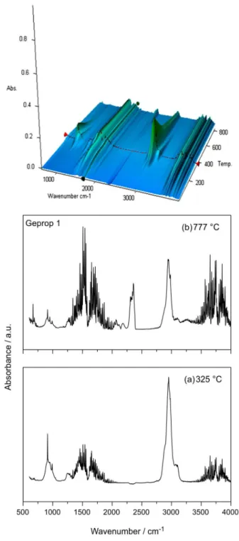
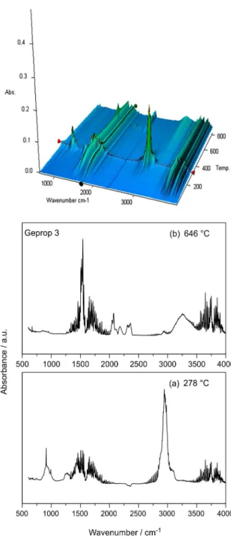
spectrometer. The 3D TG/FTIR images of these samples are shown in Figures 12, 13 and 14, together with the spectra extracted from TG/FTIR image at selected temperatures. From Figure 12a, which shows the spectra extracted from 3D TG/FTIR image of Geprop 1 sample, it can be observed that at 325 °C the bands at the ranges 3950-3448 cm-1, 3145-2730 cm-1, 1899-1181 cm-1 and
1041-813 cm-1 appear. In Figure 12b, bands are seen at
3957-3518 cm-1 range, and at 3255, 2180 and 2075 cm-1.
Bands at 1870-1269 cm-1 range are also observed. These
absorption bands in the FTIR spectrum are an indicative of the release of some compounds from thermal degradation of Geprop samples, and the bands are assigned to H2S,
propylene sulfide, ethene, propylene, ethylene sulfide and propylene sulfide, HCl, dimethyl sulfide and methanethiol. These data are in agreement with those usually observed in the decomposition of polysulfides.27,38,39
Polysulfides are very similar in organic backbone structure to these Geprop samples. They are generally stable up to 402 °C and decompose after 502 °C, with the main volatile product being hydrogen sulfide.40 For poly
(ethylene sulfide), another polymer with similar structure and stable up to 230 °C, the major gas products identified were H2S, ethylene, and ethanethiol.38 Wragg41 investigated
the thermal stability of propylene sulfide, finding thermal stability up to the temperature range 220-250 °C and the main gas products formed from thermal degradation
analyzed by infrared spectroscopy and being identified as butanethiol, diethyl sulfide, ethylene sulfide, ethanethiol, hydrogen sulfide and ethylene.
3D TG/FTIR spectra of Geprop 2 and Geprop 3 (Figures 13 and 14, respectively) are similar to those observed for Geprop 1 sample (Figure 12). This behavior suggests that Geprop samples present a similar thermal decomposition profile.
DSC
DSC curves for samples are observed in Figure 15. Vitreous transition temperature, Tg, events are observed
bellow 0 °C. The Tg obtained for these Geprop 1, Geprop 2
and Geprop 3 samples are −37 °C, −56 °C and −59 °C,
respectively. Similar results were found by Fitch and Helgeson42 for decamethylene polysulfide, [(CH
2)10Sx]n,
where for x = 2, 3, 4 or 6.4 they obtained Tg values of
−65 °C, −70 °C, −76 °C and −80 °C, respectively.
Conclusions
Figure 12. 3D TG/FTIR image from vapor phase of Geprop 1 sample and spectra extracted from 3D TG/FTIR image at temperatures (a) 325 and (b) 777 °C.
Figure 13. 3D TG/FTIR image from vapor phase of Geprop 2 sample and spectra extracted from 3D TG/FTIR image at temperatures (a) 279, (b) 330 and (c) 777 °C.
high transparency (ca. 73%) shown through UV-Vis measurements. TG curves show relatively high thermal stability of these polymers up to 200 °C and DSC curves present the Tg located at low temperatures (−37 °C, −56 °C
and −59 °C). SEM images showed that these polymers are
homogeneous, with no observed porosity, and presented formation of crystals in some regions of the surface. Besides these properties, applications as matrix for optical materials are being exploited.
Acknowledgments
Figure 14. 3D TG/FTIR image from vapor phase of Geprop 3 sample and spectra extracted from 3D TG/FTIR image at temperatures (a) 278 and (b) 646 °C.
-100 -50 0 50 100 150 200
-500 -400 -300 -200 -100 0 100 200 300
(b) Geprop 2 200 °C (c) Geprop 3 200 °C
Heat
flux / (mW mg
)
-1
Temperature / °C
(a) Geprop 1 200 °C
Exo
Figure 15. DSC curves (second heating) of (a) Geprop 1; (b) Geprop 2 and (c) Geprop 3.
Research Chairs (CERC on Enabling Photonic Innovations for Information and Communication), Ministère du Développement économique, de l’Innovation et de l’Exportation (MDEIE), Fonds de recherche du Québec - Nature et technologies (FQRNT). The Canadian ELAP Program and Dr. Y. Messaddeq, Dr. S. Messaddeq and Dr. J. Viens from COPL-ULaval University are also acknowledged.
References
1. Curry, R. J.; Mairaj, A. K.; Huang, C. C.; Eason, R. W.; Grivas, C.; Hewak, D. W.; Badding, J. V.; J. Am. Ceram. Soc.
2005, 88, 2451.
2. Novak, J.; Novak, S.; Dussauze, M.; Fargin, E.; Adamietz, F.; Musgraves, J. D.; Richardson, K.; Mater. Res. Bull. 2013, 48, 1250.
3. Waldmann, M.; Musgraves, J. D.; Richardson, K.; Arnold, C. B.;
J. Mater. Chem. 2012, 22, 17848.
4. MacLachlan, M. J.; Petrov, S.; Bedard, R. L.; Manners, I.; Ozin, G. A.; Angew. Chem. Int. Ed. 1998, 37, 2076.
5. Messaddeq, S. H.; Berube, J. P.; Bernier, M.; Skripachev, I.; Vallee, R.; Messaddeq, Y.; Opt. Express 2012, 20, 2824. 6. Lisboa-Filho, P. N.; Mastelaro, V. R.; Schreiner, W. H.;
Messaddeq, S. H.; Li, M. S.; Messaddeq, Y.; Hammer, P.; Ribeiro, S. J. L.; Parent, P.; Laffon, C.; Solid State Ionics 2005,
176, 1403.
7. Canciamilla, A.; Morichetti, F.; Grillanda, S.; Velha, P.; Sorel, M.; Singh, V.; Agarwal, A.; Kimerling, L. C.; Melloni, A.;
Optics Express 2012, 20, 15807
8. Shtutina, S.; Klebanov, M.; Lyubin, V.; Rosenwaks, S.; Volterra, V.; Thin Solid Films 1995, 261, 263.
9. Messaddeq, S. H.; Li, M. S.; Inoue, S.; Ribeiro, S. J. L.; Messaddeq, Y.; Appl. Surf. Sci. 2006, 252, 8738.
10. Varshneya, A. K.; Fundamentals of Inorganic Glasses; Academic Press, Inc.: Boston, 1994.
11. Stanic, V.; Etsell, T. H.; Pierre, A. C.; Mikula, R. J.; J. Mater. Chem. 1997, 7, 105.
12. Ferrari, J. L.; Lima, K. O.; Maia, L. J. Q.; Goncalves, R. R.;
Thin Solid Films 2010, 519, 1319.
13. Pissetti, F. L.; Francisco, M. S. P.; Landers, R.; Gushikem, Y.;
J. Braz. Chem. Soc. 2007, 18, 976.
15. Sanghera, J. S.; Scotto, C.; Bayya, S.; Aggarwal, I. D.; J. Non-Cryst. Solids 1999, 256, 31.
16. Seddon, A. B.; Hodgson, S. N. B.; Scott, M. G.; J. Mater. Sci.
1991, 26, 2599.
17. Kalebaila, K. K.; Georgiev, D. G.; Brock, S. L.; J. Non-Cryst. Solids 2006, 352, 232.
18. Namnabat, S.; Norwood, R.; Dereniak, E.; Griebel, J.; Pyun, J.;
SPIE Newsroom, in press, DOI 10.1117/2.1201407.005508. 19. Shoda, S. I.; Iwata, S.; Kim, H. J.; Hiraishi, M.; Kobayashi, S.;
Macromol. Chem. Phys. 1996, 197, 2437.
20. Nellis, D. M.; Ko, Y. H.; Tan, K. M.; Koch, S.; Parise, J. B.;
J. Chem. Soc., Chem. Commun. 1995, 5, 541.
21. Namnabat, S.; Gabriel, J. J.; Pyun, J.; Norwood, R. A.; Proc. SPIE, in press, DOI 10.1117/12.2040771.
22. Chung, W. J.; Griebel, J. J.; Kim, E. T.; Yoon, H.; Simmonds, A. G.; Ji, H. J.; Dirlam, P. T.; Glass, R. S.; Wie, J. J.; Nguyen, N. A.; Guralnick, B. W.; Park, J.; Somogyi, A.; Theato, P.; Mackay, M. E.; Sung, Y. E.; Char, K.; Pyun, J.; Nat. Chem.
2013, 5, 518.
23. Griebel, J. J.; Namnabat, S.; Kim, E. T.; Himmelhuber, R.; Moronta, D. H.; Chung, W. J.; Simmonds, A. G.; Kim, K. J.; van der Laan, J.; Nguyen, N. A.; Dereniak, E. L.; Mackay, M. E.; Char, K.; Glass, R. S.; Norwood, R. A.; Pyun, J.; Adv.Mater.
2014, 26, 3014.
24. Gutierrez-Heredia, G.; Mejia, I.; Rivas-Aguilar, M. E.; H e r n a n d e z - C o m o , N . ; M a r t i n e z - L a n d e r o s , V. H . ; Aguirre-Tostado, F. S.; Quevedo-Lopez, M. A.; Thin Solid Films 2013, 545, 458.
25. Jin, B. K.; Cho, Y. C.; Shin, D. W.; Choi, Y. G.; J. Ceram. Process. Res. 2012, 13, S110.
26. Catauro, M.; Luciani, G.; Laudisio, G.; J. Mater. Sci. Lett. 1998,
17, 1199.
27. Socrates, G., Infrared and Raman characteristic group frequencies: tables and charts, 3rd ed.; Wiley: New York, USA,
2001.
28. Micoulaut, M.; Cormier, L.; Henderson, G. S.; J. Phys.: Condens. Matter 2006, 18, R753.
29. Heo, J.; Yoon, J. M.; Ryou, S. Y.; J. Non-Cryst. Solids 1998,
238, 115.
30. Ward, A. T.; J. Phys. Chem. 1968, 72, 4133.
31. Aggarwal, R. L.; Farrar, L. W.; Polla, D. L.; J. Raman Spectrosc.
2011, 42, 461.
32. Reparaz, J. S.; Peica, N.; Kirste, R.; Goni, A. R.; Wagner, M. R.; Callsen, G.; Alonso, M. I.; Garriga, M.; Marcus, I. C.; Ronda, A.; Berbezier, I.; Maultzsch, J.; Thomsen, C.; Hoffmann, A.; Nanotechnology 2013, 24, 185704.
33. Liu, J. L.; Tang, Y. S.; Wang, K. L.; Radetic, T.; Gronsky, R.;
Appl. Phys. Lett. 1999, 74, 1863.
34. Huang, C. C.; Hewak, D. W.; Badding, J. V.; Opt. Express 2004,
12, 2501.
35. Mateleshko, N.; Mitsa, V.; Holomb, R.; Phys. B (Amsterdam, Neth.) 2004, 349, 30.
36. Mendes, A. C.; Maia, L. J. Q.; Messaddeq, S. H.; Messaddeq, Y.; Zanatta, A. R.; Li, M. S.; Curr. Appl. Phys. 2010, 10, 1411. 37. Montaudo, G.; Puglisi, C.; de Leeuw, J. W.; Hartgers, W.;
Kishore, K.; Ganesh, K.; Macromolecules 1996, 29, 6466. 38. Catsiff, E. H.; Gillis, M. N.; Gobran, R. H.; J. Polym. Sci.,
Part A: Polym. Chem. 1971, 9, 1271.
39. https://secure2.pnl.gov/nsd/nsd.nsf/Welcome accessed on February, 2015.
40. Beyler, C. L.; Hirschler, M. M.; In SFPE Handbook of Fire Protection Engineering, 4th ed.; DiNenno, P. J.; eds.; Natl Fire
Protection Assn: Quincy, 2008, ch. 7, pp. 1-110 to 1-131. 41. Wragg, R. T.; J. Chem. Soc. B 1970, 404.
42. Fitch, R. M.; Helgeson, D. C.; J. Polym. Sci., Part C: Polym. Symp. 1969, 22, 1101.
Submitted: October 8, 2014
Published online: March 20, 2015