Universidade de Aveiro 2009
Departamento de Engenharia Civil
Nuno Filipe Ferreira
Soares Borges Lopes
Comportamento ao fogo de estruturas em aço
inoxidável
Universidade de Aveiro 2009
Departamento de Engenharia Civil
Nuno Filipe Ferreira
Soares Borges Lopes
Comportamento ao fogo de estruturas em aço
inoxidável
Dissertação apresentada à Universidade de Aveiro para cumprimento dos requisitos necessários à obtenção do grau de Doutor em Engenharia Civil, realizada sob a orientação científica do Doutor Paulo Jorge de Melo Matias Faria de Vila Real, Professor Catedrático da Universidade de Aveiro e co-orientação do Doutor Luís Alberto Proença Simões da Silva, Professor Catedrático da Universidade de Coimbra
Universidade de Aveiro 2009
Departamento de Engenharia Civil
Nuno Filipe Ferreira
Soares Borges Lopes
Behaviour of stainless steel structures in case of fire
Thesis submitted to the University of Aveiro to fulfil the necessary requirements for the degree of Doctor of Philosophy in Civil Engineering, made under the scientific supervision of Doctor Paulo Jorge de Melo Matias Faria de Vila Real, Professor at the University of Aveiro and co-supervision of Doctor Luís Alberto Proença Simões da Silva, Professor at the University of Coimbra.
Aos meus pais To my parents
o júri
presidente Prof. Doutor Casimiro Adrião Pio
professor catedrático da Universidade de Aveiro
Prof. Doutor Enrique Mirambell Arrizabalaga
professor catedrático da Universidade Politécnica de Catalunha
Prof. Doutor Peter Schaumann
professor catedrático da Universidade de Hanôver
Prof. Doutor Jean-Marc Franssen
professor catedrático da Universidade de Liège
Prof. Doutor Luís Alberto Proença Simões da Silva
professor catedrático da Faculdade de Ciências e Tecnologia da Universidade de Coimbra
Prof. Doutor Paulo Jorge de Melo Matias Faria de Vila Real
professor catedrático da Universidade de Aveiro
Prof. Doutor Dinar Reis Zamith Camotim
professor associado do Instituto Superior Técnico da Universidade Técnica de Lisboa
Prof. Doutor Paulo Barreto Cachim
professor associado da Universidade de Aveiro
Prof. Doutor João Paulo Correia Rodrigues
professor auxiliar da Faculdade de Ciências e Tecnologia da Universidade de Coimbra
Prof. Doutor Paulo Alexandre Gonçalves Piloto
the jury
chairman Prof. Doctor Casimiro Adrião Pio
professor at the University of Aveiro
Prof. Doctor Enrique Mirambell Arrizabalaga
professor at the Polytechnic University of Catalonia
Prof. Doctor Peter Schaumann
professor at the University of Hanover
Prof. Doctor Jean-Marc Franssen
professor at the University of Liege
Prof. Doctor Luís Alberto Proença Simões da Silva
professor at the Faculty of Science and Technology of the University of Coimbra
Prof. Doctor Paulo Jorge de Melo Matias Faria de Vila Real
professor at the University of Aveiro
Prof. Doctor Dinar Reis Zamith Camotim
associate professor at the Superior Technical Institute of the Technical University of Lisbon
Prof. Doctor Paulo Barreto Cachim
associate professor at the University of Aveiro
Prof. Doctor João Paulo Correia Rodrigues
assistant professor at the Faculty of Science and Technology of the University of Coimbra
Prof. Doctor Paulo Alexandre Gonçalves Piloto
agradecimentos O desenvolvimento da presente tese não seria possível sem a excelente supervisão do Professor Paulo Vila Real, meu orientador, a quem estou muito grato por todo o conhecimento, motivação e empenho transmitidos.
Ao meu co-orientador Professor Luís Simões da Silva pelas valiosas sugestões e ajudas fornecidas durante a preparação desta tese.
Estou igualmente grato ao Professor Jean-Marc Franssen, pela calorosa recepção e supervisão proporcionadas durante um ano na Universidade de Liège, Bélgica, e pelas suas claras respostas às minhas incontáveis perguntas e dúvidas.
Ao Departamento de Engenharia Civil da Universidade de Aveiro na pessoa do Professor Claudino Cardoso, presidente do departamento, pelas facilidades proporcionadas durante a preparação desta tese.
Ao Departamento ArGEnCo da Universidade de Liège na pessoa
do Professor Serge Cescotto, presidente do departamento, pelas facilidades proporcionadas durante o período que passei neste departamento.
Ao Professor Paulo Piloto pelo seu auxílio na obtenção da validação de alguns resultados numéricos. Também, ao Professor Enrique Mirambell pelas
sugestões dadas a parte do trabalho.
A todos os colegas e amigos da Universidade de Aveiro e da Universidade de Liège pelas ajudas e incentivos, em particular a Carlos Coelho, José Alexandre Henriques, François Hanus, David Janssen e Barbara Rossi. À Fundação Calouste Gulbenkian pelo apoio financeiro dado durante minha estadia na Universidade de Liège.
À Fundação para a Ciência e a Tecnologia pelo apoio financeiro dado sob a forma de bolsa de doutoramento.
Aos meus pais e irmãos pelos sempre disponíveis apoio e motivação. Muito obrigado
acknowledgements The development of this thesis would not be possible without the excellent guidance of Professor Paulo Vila Real, my supervisor, to whom I am very grateful for all the transmitted knowledge, encouragement and dedication. I wish to acknowledge my co-supervisor Professor Luís Simões da Silva for the valuable suggestions and help given during the preparation of this thesis. I am also grateful to Professor Jean-Marc Franssen, for the warm welcome and supervision provided during one year at the University of Liege, Belgium, and for his clear answers to my countless questions and doubts.
To the Department of Civil Engineering of the University of Aveiro in the person of Professor Claudino Cardoso, president of the department, for the facilities provided during the preparation of this thesis.
To the Department ArGEnCo of the University of Liege in the person of Professor Serge Cescotto, president of the department, for the facilities provided during the period that I spent in this department.
To Professor Paulo Piloto for his assistance in the achievement of the validation of some numerical results. Also, to Professor Enrique Mirambell for the consultancy provided to part of the work.
To all colleagues and friends from the University of Aveiro and from
the University of Liege for the help and encouragement, in particular to Carlos Coelho, José Alexandre Henriques, François Hanus, David Janssen and Barbara Rossi.
To the Calouste Gulbenkian Foundation (Fundação Calouste Gulbenkian) for the financial support given during my stay in the University of Liege.
To the Foundation for Science and Technology (Fundação para a Ciência e a Tecnologia) for the financial support given in the form of a doctoral scholarship.
To my parents and brothers for their always available support and motivation. Many thanks
palavras-chave aço inoxidável, estruturas, fogo, encurvadura, elementos estruturais.
resumo A presente tese resulta de um trabalho de investigação, cujo objectivo se
centrou no aumento de conhecimento do comportamento estrutural do aço inoxidável, na construção.
O aço inoxidável tem várias características desejáveis num material estrutural. Embora inicialmente mais caras que em aço carbono convencional, estruturas em aço inoxidável podem ser competitivas em virtude de necessitarem de uma menor quantidade de material de protecção térmica, e de terem um custo de ciclo de vida mais baixo, contribuindo assim para uma construção mais sustentável.
O principal objectivo desta tese consiste em realizar uma avaliação numérica da resistência ao fogo de estruturas em aço inoxidável.
Os estudos numéricos foram efectuados através do programa de elementos finitos SAFIR com análises material e geométrica não lineares, que foi especialmente desenvolvido na Universidade de Liège para o estudo de estruturas em situação de incêndio. Estas análises numéricas enquadram-se na metodologia habitualmente designada por GMNIA - geometrically and
materially non-linear imperfect analysis. O programa foi também objecto de
modificações tendo em vista a realização desses estudos.
É demonstrado que, devido às diferenças existentes entre as leis constitutivas do aço carbono e do aço inoxidável, não é possível utilizar em ambos os materiais as mesmas fórmulas para o cálculo da estabilidade de elementos, como é proposto no Eurocódigo 3. Os resultados mostram também que, para alguns elementos estruturais, as fórmulas, preconizadas nessa norma
europeia, não estão do lado da segurança, existindo assim necessidade de as melhorar.
Estes estudos foram realizados em colunas, vigas e vigas-coluna em aço inoxidável tanto à temperatura ambiente como a altas temperaturas, resultando em novas propostas de dimensionamento para esses elementos. O
comportamento de vigas em aço carbono sujeitas a temperaturas elevadas foi também analisado, devido a não ser suficientemente conhecido e as propostas apresentadas nesta tese, para vigas em aço inoxidável, terem sido baseadas nesse comportamento.
Esta tese contém também um estudo em elementos de paredes finas em aço inoxidável sujeitos a incêndio, onde é avaliada a influência das tensões residuais nas suas cargas últimas.
Por fim apresenta-se uma análise do comportamento estrutural global de duas estruturas em aço inoxidável sujeitas a incêndio, comparando os resultados obtidos com o comportamento das mesmas estruturas em aço carbono.
keywords stainless steel, structures, fire, buckling, structural elements.
abstract This thesis is a research work aimed at increasing the knowledge of the
structural behaviour of the stainless steel in construction.
The stainless steel has countless desirable characteristics for a structural material. Although initially more expensive than conventional carbon steel, stainless steel structures can be competitive because of its smaller need for thermal protection material, and lower life-cycle cost, thus contributing to a more sustainable construction.
The main objective of this thesis consists in making a numerical evaluation of the fire resistance of stainless steel structures.
The numerical studies were performed using the finite element program SAFIR, with non-linear material and geometric analysis, which was specially developed at the University of Liege, for the study of structures in case of fire. These numerical analyses fit the methodology usually designated GMNIA -
geometrically and materially non-linear imperfect analysis. The program was also object of some modifications in order to enable those studies.
It is demonstrated that, due to the existing differences in the constitutive laws of carbon steel and stainless steel, it is not possible to use in both materials the same formulae for the member stability calculation, as proposed in Eurocode 3. Moreover, the results show that, the formulae, prescribed on that european norm, are not on the safe side for some structural elements, being necessary their improvement.
These studies were made in stainless steel columns, beams and
beam-columns at room temperature and at high temperatures, resulting in new design proposals for those members. The behaviour of carbon steel beams at elevated temperatures was also analysed, due to not being sufficiently known and to the proposals presented in this thesis, for stainless steel beams, being based on that behaviour.
This thesis contains also a study on thin-walled stainless steel elements in case of fire, where it is evaluated the influence of the residual stresses on their ultimate loads.
Finally, an analysis on the global structural behaviour of two stainless steel structures subjected to fire is presented, followed by a comparison of their results with the behaviour of the same structures in carbon steel.
mots-clés acier inoxydable, structures, feu, déversement, éléments structurels.
résumé La présente thèse est un travail de recherche, avec l'objectif d’élever la
connaissance du comportement structurel de l'acier inoxydable, dans la construction.
L'acier inoxydable a plusieurs caractéristiques souhaitables dans un matériau structurel. Même initialement plus chères qu‘en acier au carbone traditionnel, les structures en acier inoxydable peuvent être compétitives car elles
nécessitent la mise en place d’une quantité moins importante de protection thermique, et induisent un coût de cycle de vie plus faible, contribuant ainsi à une construction plus durable.
Le principal objectif de cette thèse consiste à réaliser une évaluation numérique de la résistance au feu des structures en acier inoxydable. Les études numériques ont été réalisées avec le programme d'éléments finis SAFIR, d'analyse non linéaire matérielle et géométrique, et qui a été spécialement développé à l'Université de Liège pour l'étude des structures soumises au feu. Ces études numériques s'inscrivent dans la méthodologie habituellement désignée de GMNIA - geometrically and materially non-linear
imperfect analysis. Le programme a été aussi l’objet de quelques modifications
afin de rendre possibles ces études.
On démontre que, en raison des différences existantes dans les lois
constitutives de l'acier au carbone et de l'acier inoxydable, il n'est pas possible d’employer dans les deux matériaux les mêmes formules pour le calcul de stabilité d'éléments, comme proposé dans l'Eurocode 3. Les résultats prouvent aussi que les formules préconisées dans cette norme européenne ne sont pas du côté de la sécurité pour quelques éléments structurels, ce qui suggère leur amélioration.
Ces études ont été effectuées dans des poteaux, des poutres et des poutres-poteaux d'acier inoxydable à la température ambiante et à hautes
températures, les études ont résulté en nouveaux propositions de calcul pour ces éléments. Le comportement des poutres en acier au carbone soumises à des températures élevées est également étudié, car sa connaissance est insuffisante et des propositions présentées dans cette thèse, pour le calcul des poutres en acier inoxydable, êtres basés sur ce comportement.
Cette thèse contient aussi une étude des éléments à parois minces en acier inoxydable soumis au feu, où l’influence des contraintes résiduelles sur les charges ultimes est avalisée.
Finalement, une évaluation du comportement structurel global de deux structures d'acier inoxydable en cas de feu est présentée, et les résultats sont comparés à ceux obtenus dans le cas de structures similaires en acier au carbone.
Contents
xxi
Contents
Acknowledgements Abstract
Resumo (Portuguese abstract) Résumé (French abstract)
Contents xxi
List of figures xxvii
List of tables xxxvii
Notation xli
Chapter 1. Introduction
1.1 General considerations 3 1.2 Objectives 7 1.3 Thesis outline 8Chapter 2. Materials
2.1 Introduction 13 2.2 Stainless steel 132.2.1 Stainless steel grades 13
2.2.2 Mechanical properties 15
2.2.3 Thermal properties 23
2.3 Comparison between stainless steel and carbon steel 23
2.3.1 Mechanical properties 24
2.3.2 Thermal properties 29
Behaviour of stainless steel structures in case of fire
xxii
Chapter 3. Numerical analysis
3.1 Introduction 35
3.2 The software SAFIR 35
3.2.1 General description 36
3.2.1.1 Thermal analysis 36
3.2.1.2 Torsional analysis 38
3.2.1.3 Structural analysis 39
3.2.1.3.1 Beam finite elements 41
3.2.1.3.2 Shell finite element 43
3.2.1.3.3 Global structural analysis in case of fire 44
3.2.2 Software development 45
3.2.2.1 Introduction of one-dimensional mechanical properties of stainless
steel 46 3.2.2.2 Introduction of two-dimensional mechanical properties of stainless
steel 47
3.2.2.3 Consideration of residual stresses in shell elements 50
3.3 Numerical models 52
3.3.1 General description 53
3.3.2 Validation of the software development 56
3.3.2.1 Introduction of one-dimensional mechanical properties of the
stainless steels 57
3.3.2.2 Introduction of two-dimensional mechanical properties of the
stainless steels 58
3.3.2.3 Consideration of residual stresses in shell elements 59
3.4 Conclusions 61
Chapter 4. Prescribed design rules for structural elements
4.1 Introduction 65
4.2 Design rules at room temperature 66
Contents
xxiii
4.2.1.1 Eurocode recommendations 67
4.2.1.2 Comparison against numerical results 68
4.2.2 Bending 69
4.2.2.1 Eurocode recommendations 70
4.2.2.2 Comparison against numerical results 73
4.2.3 Bending and axial compression 75
4.2.3.1 Without lateral torsional buckling 75
4.2.3.1.1 Eurocode recommendations 76
4.2.3.1.2 Comparison against numerical results 76
4.2.3.2 With lateral torsional buckling 79
4.2.3.2.1 Eurocode recommendations 79
4.2.3.2.2 Comparison against numerical results 79
4.3 Design rules at high temperatures 81
4.3.1 Compression 82
4.3.1.1 Eurocode recommendations 83
4.3.1.2 Comparison against numerical results 84
4.3.2 Bending 84
4.3.2.1 Eurocode recommendations 85
4.3.2.2 Comparison against numerical results 86
4.3.3 Bending and axial compression 88
4.3.3.1 Without lateral torsional buckling 89
4.3.3.1.1 Original proposal for carbon steel elements 89
4.3.3.1.2 Interaction curves 90
4.3.3.1.3 Parametric study in carbon steel elements 91
4.3.3.1.4 Comparison against stainless steel numerical results 95
4.3.3.2 With lateral torsional buckling 98
4.3.3.2.1 Eurocode recommendations 98
4.3.3.2.2 Comparison against numerical results 98
4.3.4 Lateral torsional buckling design proposal in carbon steel members 101
4.3.4.1 Case study 101
4.3.4.2 The lateral torsional buckling code provisions of Eurocode 3 103
Behaviour of stainless steel structures in case of fire
xxiv
4.3.4.2.2 Lateral torsional buckling at high temperatures 107
4.3.4.3 Improvement of Eurocode 3 formulae at high temperatures: a new
proposal 112
4.3.4.4 Accuracy of the proposal 115
4.3.4.5 Interaction formulae for beam-columns 120
4.4 Conclusions 122
Chapter 5. Design proposals for stainless steel structural elements
5.1 Introduction 127
5.2 At room temperature 128
5.2.1 Compression 128
5.2.1.1 Case study 128
5.2.1.2 Improvement of the Eurocode 3 formulae: a new proposal 129
5.2.1.3 Accuracy of the proposal 130
5.2.2 Bending 135
5.2.2.1 Case study 136
5.2.2.2 Improvement of the Eurocode 3 formulae: a new proposal 137
5.2.2.3 Accuracy of the proposal 139
5.2.3 Bending and axial compression 143
5.2.3.1 Without lateral torsional buckling 143
5.2.3.1.1 Case study 144
5.2.3.1.2 Adaptation of the carbon steel interaction curves 144
5.2.3.1.3 Formulation of a new proposal 146
5.2.3.1.4 Accuracy of the proposals 150
5.2.3.2 With lateral torsional buckling 154
5.2.3.2.1 Case study 154
5.2.3.2.2 Adaptation of the carbon steel interaction curves 155
5.2.3.2.3 Formulation of a new proposal 157
5.2.3.2.4 Accuracy of the proposals 159
5.3 At high temperatures 162
Contents
xxv
5.3.1.1 Case study 162
5.3.1.2 Improvement of the Eurocode 3 formulae: a new proposal 163
5.3.1.3 Accuracy of the proposal 165
5.3.2 Bending 171
5.3.2.1 Case study 171
5.3.2.2 Improvement of the Eurocode 3 formulae: a new proposal 172
5.3.2.3 Accuracy of the proposal 175
5.3.3 Bending and axial compression 179
5.3.3.1 Without lateral torsional buckling 180
5.3.3.1.1 Case study 180
5.3.3.1.2 Formulation of a new proposal 180
5.3.3.1.3 Accuracy of the proposals 187
5.3.3.2 With lateral torsional buckling 193
5.3.3.2.1 Case study 194
5.3.3.2.2 Formulation of a new proposal 194
5.3.3.2.3 Accuracy of the proposals 196
5.4 Conclusions 199
Chapter 6. Thin-walled stainless steel structural elements in case of
fire
6.1 Introduction 203
6.2 Thin-walled sections 203
6.2.1 Plate buckling 204
6.2.2 Thin-walled sections in case of fire 206
6.3 Residual stresses in stainless steel elements with thin-walled sections 207
6.3.1 Axially loaded square hollow sections 208
6.3.2 Welded I-sections in bending 212
Behaviour of stainless steel structures in case of fire
xxvi
Chapter 7. Global behaviour of stainless steel structures in case of
fire
7.1 Introduction 219
7.2 Actions in structures subjected to fire 220
7.2.1 Mechanical actions 221
7.2.2 Thermal actions 221
7.3 Application examples 222
7.3.1 A sport hall truss structure 222
7.3.2 An office building portal frame 228
7.4 Conclusions 235
Chapter 8. Conclusions
8.1 General conclusions 239 8.2 Design recommendations 240 8.3 Future work 241 8.3.1 Experimental tests 2418.3.2 Different cross-sections shapes, loading types and bi-axial bending 242
8.3.3 Eurocode 3 validation for thin-walled stainless steel sections in case of
fire 242
8.3.4 Life cycle costing 242
List of figures
xxvii
List of figures
Chapter 1. Introduction
Figure 1.1 – Schematic representation of the outline of the thesis. 9
Chapter 2. Materials
Figure 2.1 – Types of stainless steel (ESDEP, 2000). 14
Figure 2.2 – Stress-strain relationship of the stainless steel at high temperatures
(CEN, 2005b). 16
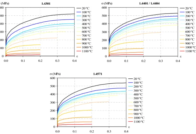
Figure 2.3 – Stress-strain relationship of the austenitic stainless steels at high
temperatures. 20 Figure 2.4 – Stress-strain relationship of the ferritic and austenitic-ferritic stainless
steels at high temperatures. 20
Figure 2.5 – Stress-strain relationship of the stainless steel 1.4301 at 1100 ºC. 21
Figure 2.6 – Value of equation (2.3) for the stainless steel 1.4301. 22
Figure 2.7 – Stress-strain relationship of the carbon steel at elevated temperatures. 25 Figure 2.8 – Stress-strain relationship of the carbon steel in function of the
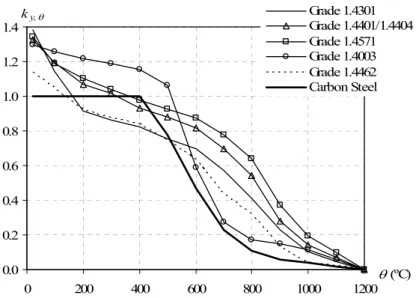
temperature. 26 Figure 2.9 – Reduction factor of the yield strength of carbon steel and stainless
steel. 27
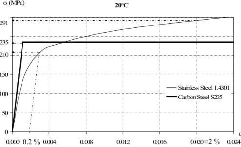
Figure 2.10 – Part of the stress-strain relationships from stainless steel 1.4301 and
carbon steel S235. 28
Figure 2.11 – Comparison of the modulus of elasticity reduction at high
temperatures. 28 Figure 2.12 – Comparison of the thermal elongation in function of the
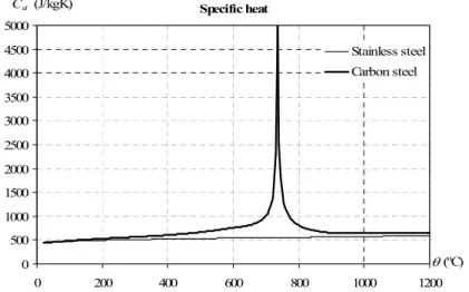
temperature. 29 Figure 2.13 – Comparison of the specific heat in function of the temperature. 30
Behaviour of stainless steel structures in case of fire
xxviii
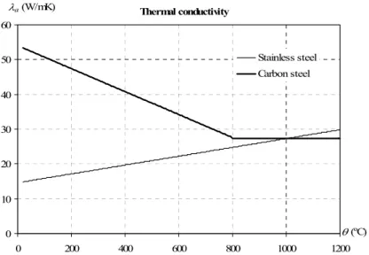
Figure 2.14 – Comparison of the thermal conductivity in function of the
temperature. 31
Chapter 3. Numerical analysis
Figure 3.1 – Mesh of an I-cross-section. 37
Figure 3.2 – Mesh of a structure. 39
Figure 3.3 – 2D beam finite element. 42
Figure 3.4 – 3D beam finite element. 42
Figure 3.5 – Shell finite element. 44
Figure 3.6 – Steel kinematical material model to account the temperature
evolution. 45
Figure 3.7 – Masing’s rule in stainless steel grade 1.4301 at 600 ºC. 46
Figure 3.8 – Determination of the hardening rule. 48
Figure 3.9 – Stainless steel constitutive law: comparison between the
approximation used for 2D analysis and the EC3 at 600 ºC, for the stainless
steel grade 1.4301. 49
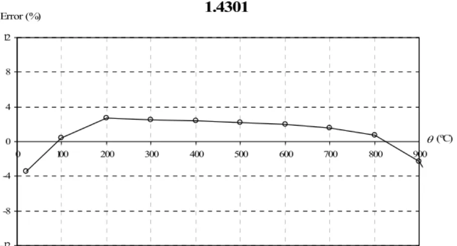
Figure 3.10 – Average error between the approximation used for 2D analysis and
the EC3, for the stainless steel grade 1.4301. 50
Figure 3.11 – Consideration of residual strains in non-linear constitutive laws. 51 Figure 3.12 – Comparison between introduced residual stresses and obtained ones
with the implemented procedure. 52
Figure 3.13 – Residual stresses in I-hot rolled sections (C – compression; T –
tension). 55 Figure 3.14 – Residual stresses in I-welded sections (C – compression; T –
tension). 55
Figure 3.15 – An initial rotation around the longitudinal axis at mid span. 56
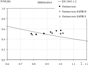
Figure 3.16 – SHS40x40x4 numerical results using beam finite elements. 57
Figure 3.17 – SHS40x40x4 numerical results with SAFIR using beam and shell
finite elements compared with the experimental tests. 58
Figure 3.18 – SHS40x40x4 column simulated with shell elements. 59
List of figures
xxix
Figure 3.20 – Simply supported stainless steel beam subjected to uniform
bending. 61
Chapter 4. Prescribed design rules for structural elements
Figure 4.1 – Element subjected to axial compression (column). 67
Figure 4.2 – Comparison between the curve from EC3 and the numerical results:
buckling about the strong axis and the weak axis. 69
Figure 4.3 – Element subjected to bending (beam). 70
Figure 4.4 – Deformed shape of a steel I-beam due to LTB. 70
Figure 4.5 – Comparison between the numerical results and the EC3 for welded
IPE220 beams of the stainless steel grade 1.4301. 74
Figure 4.6 – Element subjected to axial compression and bending (beam-column). 75 Figure 4.7 – Comparison between the numerical results and the EC3 for welded
HEA200 beam-columns of the stainless steel grade 1.4301, regarding the
buckling mode and uni-axial bending about the strong axis. 77
Figure 4.8 – Comparison between the numerical results and the EC3 for welded HEA200 beam-columns of the stainless steel grade 1.4301, regarding the
buckling mode and uni-axial bending about the weak axis. 78
Figure 4.9 – Comparison between the numerical results and the EC3 for welded HEA200 beam-columns of the stainless steel grade 1.4301, with LTB and
uni-axial bending about the strong axis. 80
Figure 4.10 – Reduction of the factor to determine the cross-section classes, at
high temperatures. 82
Figure 4.11 – Element subjected to axial compression in case of fire. 82
Figure 4.12 – Comparison between the curve from EC3 and the numerical results:
buckling about the strong axis and the weak axis, at high temperatures. 84
Figure 4.13 – Element subjected to bending in case of fire. 85
Figure 4.14 – Comparison between the numerical results and the EC3 for welded
IPE220 beams of the stainless steel grade 1.4301, at high temperatures. 87
Figure 4.15 – Element subjected to axial compression and bending in case of fire. 88
Behaviour of stainless steel structures in case of fire
xxx
Figure 4.17 – Comparison between the different formulae with bending on the
strong axis. 92
Figure 4.18 – Comparison between the different formulae with bending on the
weak axis. 93
Figure 4.19 – Median with uniform bending diagram on the weak axis. 94
Figure 4.20 – Comparison between the numerical results and the EC3 for welded HEA200 beam-columns, at 600 ºC, of the stainless steel grade 1.4301,
regarding the buckling mode and uni-axial bending about the strong axis. 96
Figure 4.21 – Comparison between the numerical results and the EC3 for welded HEA200 beam-columns, at 600 ºC, of the stainless steel grade 1.4301,
regarding the buckling mode and uni-axial bending about the weak axis. 97
Figure 4.22 – Comparison between the numerical results and the EC3 for welded HEA200 beam-columns, at 600 ºC, of the stainless steel grade 1.4301, with
LTB and uni-axial bending about the strong axis. 100
Figure 4.23 – Studied bending diagrams in carbon steel beams. 102
Figure 4.24 – Numerical results for an IPE220 of carbon steel grade S235 at room
temperature. 106 Figure 4.25 – Beam design curve from EN 1993-1-2: comparison with numerical
results for an IPE220. 108
Figure 4.26 – Influence of the cross-section on the LTB curve: comparison with
EN 1993-1-2. 109
Figure 4.27 – Influence of the residual stresses on the LTB curve for the HEA500:
comparison with EN 1993-1-2. 110
Figure 4.28 – Influence of the applied load on the LTB: comparison with
EN 1993-1-2. 111
Figure 4.29 – Numerical results for a welded IPE500 in carbon steel grade S460:
comparison with EN 1993 1-2. 112
Figure 4.30 – New proposal for different bending diagrams. 114
Figure 4.31 – Comparison between the EN 1993-1-2 / f, the new proposal and the
numerical results. 115
Figure 4.32 – Numerical results for a welded IPE500 of carbon steel grade S460
List of figures
xxxi
Figure 4.33 – Comparison between EN 1993-1-2, the new proposal and numerical results for the hot rolled and welded HEA500, IPE220 and IPE500 in carbon
steel grade S235, S355 and S460. 118
Figure 4.34 – Ratio between analytical and SAFIR, for EN 1993-1-2 with hot
rolled IPE220 in carbon steel grade S235 and S355. 119
Figure 4.35 – Ratio between analytical and SAFIR, for EN 1993-1-2 with the hot rolled and welded HEA500, IPE220 and IPE500 in carbon steel grade S235,
S355 and S460. 119
Figure 4.36 – Ratio between analytical and SAFIR, for the new proposal with the hot rolled and welded HEA500, IPE220 and IPE500 in carbon steel grade
S235, S355 and S460. 119
Figure 4.37 – Studied bending diagrams in carbon steel beam-columns. 120
Figure 4.38 – Interaction diagrams of EN 1993-1-2, for triangular bending
moment diagrams. 121
Figure 4.39 – Interaction diagrams of EN 1993-1-2, for bi-triangular bending
moment diagrams. 121
Chapter 5. Design proposals for stainless steel structural elements
Figure 5.1 – Column with cross-section HEA200 in stainless steel grade 1.4301. 131 Figure 5.2 – Column with cross-section HEB200 in stainless steel grade 1.4462. 132 Figure 5.3 – Comparison between EN 1993-1-4, the new proposal and numerical
results for the strong axis. 133
Figure 5.4 – Comparison between EN 1993-1-4, the new proposal and numerical
results for the weak axis. 133
Figure 5.5 – Ratio between analytical and SAFIR results, for EN 1993-1-4 in the
strong axis. 134
Figure 5.6 – Ratio between analytical and SAFIR results, for the new proposal in
the strong axis. 134
Figure 5.7 – Ratio between analytical and SAFIR results, for EN 1993-1-4 in the
Behaviour of stainless steel structures in case of fire
xxxii
Figure 5.8 – Ratio between analytical and SAFIR results, for the new proposal in
the weak axis. 135
Figure 5.9 – Imperfection factor for the LTB in function of the cross-section
slenderness. 138 Figure 5.10 – Numerical results for a welded IPE220 of stainless steel grade
1.4301. 140 Figure 5.11 – Numerical results for a welded HEA200 of stainless steel grade
1.4301. 141 Figure 5.12 – Comparison between EN 1993-1-4 and numerical results with LTB. 142
Figure 5.13 – Ratio between analytical and SAFIR results, for EN 1993-1-4. 142
Figure 5.14 – Ratio between analytical and SAFIR results, for the new proposal. 143
Figure 5.15 – Formulation of new interaction curves for the strong axis. 148
Figure 5.16 – Formulation of new interaction curves for the weak axis. 149
Figure 5.17 – Comparison between different interaction curves for welded HEA200 beam-columns of the stainless steel grade 1.4301, regarding the
buckling mode and uni-axial bending about the strong axis. 151
Figure 5.18 – Comparison between different interaction curves for welded HEA200 beam-columns of the stainless steel grade 1.4301, regarding the
buckling mode and uni-axial bending about the weak axis. 152
Figure 5.19 – Comparison between the proposals and the numerical results for the
strong axis. 153
Figure 5.20 – Comparison between the proposals and the numerical results for the
weak axis. 154
Figure 5.21 – Formulation of new interaction curves for beam-columns with LTB. 158 Figure 5.22 – Comparison between different interaction curves for welded
HEA200 beam-columns of the stainless steel grade 1.4301, with LTB. 160
Figure 5.23 – Comparison between the proposals and the numerical results with
LTB. 161
Figure 5.24 – Slenderness variation at high temperatures. 164
Figure 5.25 – Column with cross-section HEA200 in stainless steel grade 1.4301,
List of figures
xxxiii
Figure 5.26 – Column with cross-section HEB200 in stainless steel grade 1.4003,
at high temperatures. 167
Figure 5.27 – Comparison between EN 1993-1-2, the new proposal and numerical
results for the strong axis, at high temperatures. 168
Figure 5.28 – Comparison between EN 1993-1-2, the new proposal and numerical
results for the weak axis, at high temperatures. 169
Figure 5.29 – Ratio between analytical and SAFIR results, for EN 1993-1-2 in the
strong axis, at high temperatures. 169
Figure 5.30 – Ratio between analytical and SAFIR results, for the new proposal in
the strong axis, at high temperatures. 170
Figure 5.31 – Ratio between analytical and SAFIR results, for EN 1993-1-2 in the
weak axis, at high temperatures. 170
Figure 5.32 – Ratio between analytical and SAFIR results, for the new proposal in
the weak axis, at high temperatures. 170
Figure 5.33 – Severity factor for the LTB at high temperatures in function of the
cross-section slenderness. 174
Figure 5.34 – Numerical results for a welded IPE220 of stainless steel grade
1.4301, at high temperatures. 176
Figure 5.35 – Numerical results for a welded HEA200 of stainless steel grade
1.4301, at high temperature. 177
Figure 5.36 – Numerical results for a welded IPE220 in stainless steel grade
1.4003, at high temperatures. 177
Figure 5.37 – Comparison between EN 1993-1-2 and numerical results. 178
Figure 5.38 – Ratio between analytical and SAFIR results, for EN 1993-1-2. 178
Figure 5.39 – Ratio between analytical and SAFIR results, for the new proposal. 179 Figure 5.40 – Interaction curve shape for different interaction factor limits. 181 Figure 5.41 – Formulation of new interaction curves for the strong axis, at high
temperatures. 183 Figure 5.42 – Formulation of new interaction curves for the weak axis, at high
temperatures. 184 Figure 5.43 – Formulation of new interaction curves for the strong axis, at high
Behaviour of stainless steel structures in case of fire
xxxiv
Figure 5.44 – Formulation of new interaction curves for the weak axis at high
temperatures, in duplex stainless steel. 186
Figure 5.45 – Comparison between different interaction curves for welded HEA200 beam-columns of the stainless steel grade 1.4301, regarding the buckling mode and uni-axial bending about the strong axis, at high
temperatures. 188 Figure 5.46 – Comparison between different interaction curves for welded
HEA200 beam-columns of the stainless steel grade 1.4301, regarding the buckling mode and uni-axial bending about the weak axis, at high
temperatures. 189 Figure 5.47 – Comparison between the proposals and the numerical results for the
strong axis, at high temperatures. 190
Figure 5.48 – Comparison between the proposals and the numerical results for the
weak axis, at high temperatures. 191
Figure 5.49 – Comparison between the proposals and the numerical results for the
strong axis, at high temperatures, in duplex stainless steel. 192
Figure 5.50 – Comparison between the proposals and the numerical results for the
weak axis, at high temperatures, in duplex stainless steel. 193
Figure 5.51 – Formulation of new interaction curves for the strong axis for
beam-columns with LTB, at high temperatures. 195
Figure 5.52 – Comparison between different interaction curves for welded HEA200 beam-columns of the stainless steel grade 1.4301, for beam-columns
with LTB, at high temperatures. 197
Figure 5.53 – Comparison between the proposals and the numerical results with
LTB, at high temperatures. 198
Chapter 6. Thin-walled stainless steel structural elements in case of
fire
Figure 6.1 – Nonlinear stress distribution of a buckled plate. 204
Figure 6.2 – Class 4 SHS buckled when subjected to axial compression. 205
List of figures
xxxv
Figure 6.4 – Used mesh in a column with a thin-walled stainless steel hollow
section. 208 Figure 6.5 – Refined mesh in a column with a thin-walled stainless steel hollow
section. 209 Figure 6.6 – Deformed shape of a column with a thin-walled stainless steel hollow
section with local imperfections. 210
Figure 6.7 – Residual stresses in the square hollow member. 211
Figure 6.8 – Axial force in function of the longitudinal displacement in the
column’s free extremity. 212
Figure 6.9 – First buckling mode obtained with the program CUFSM (Schafer,
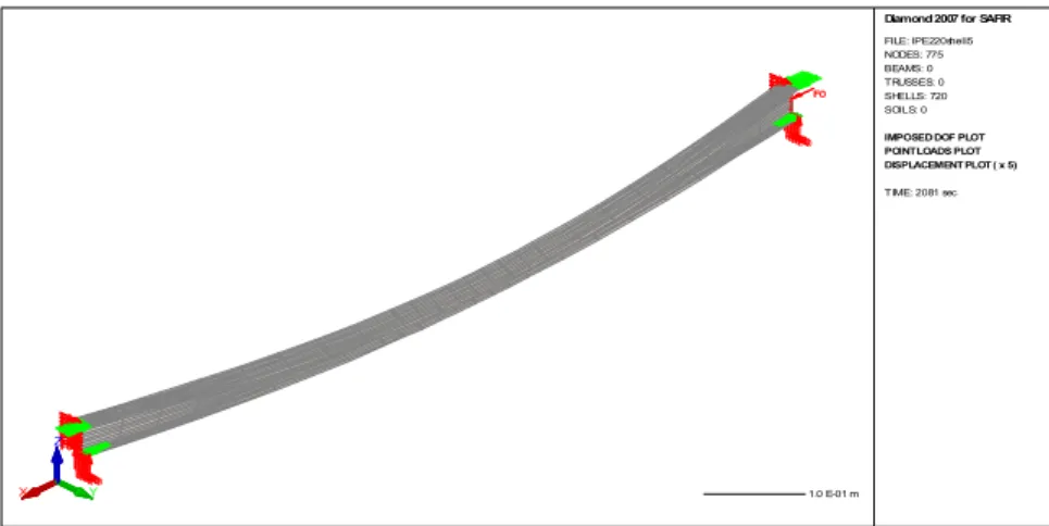
1997). 213 Figure 6.10 – Deformed shape of a stainless steel beam analysed with shell
elements. 214
Figure 6.11 – Residual stresses in the welded I-member. 215
Chapter 7. Global behaviour of stainless steel structures in case of
fire
Figure 7.1 – Analysed truss. 222
Figure 7.2 – Temperature field in the SHS70x70x4 cross-section after 15 minutes. 223
Figure 7.3 – Temperature evolution in node 41 of the SHS70x70x4. 224
Figure 7.4 – Mesh used in the truss structure. 224
Figure 7.5 – Deformed shape (x5) of the truss structure. 225
Figure 7.6 – Horizontal displacement of the simple support (node 289). 226
Figure 7.7 – Axial forces diagrams of the truss structure. 226
Figure 7.8 – Axial forces evolution over time in elements number 98 and 318. 227
Figure 7.9 – Structure with fire only in room 4. 229
Figure 7.10 – Structural elements subjected to fire. 229
Figure 7.11 – Temperature field in the beam 4 cross-section after half hour. 229 Figure 7.12 – Temperature evolution in node 188 in the beam 4 cross-section. 230 Figure 7.13 – Design loads for the accidental combination with wind as the
Behaviour of stainless steel structures in case of fire
xxxvi
Figure 7.14 – Mesh used in the portal frame. 231
Figure 7.15 – Deformed shape (x1) of the portal frame. 231
Figure 7.16 – Vertical displacement at mid span of the beam 4 (node 165). 232
Figure 7.17 – Axial forces diagrams of the portal frame. 233
Figure 7.18 – Axial forces evolution over time in elements number 23 and 81. 233
Figure 7.19 – Bending moments diagrams of the portal frame. 234
Figure 7.20 – Bending moment evolution over time in elements number 76
List of tables
xxxvii
List of tables
Chapter 2. Materials
Table 2.1 – Nominal values for the yield strength, the ultimate tensile strength and
the modulus of elasticity of structural stainless steels (CEN, 2006a). 15
Table 2.2 – Expressions to determine the stress-strain relationship of the stainless
steel at high temperatures. 16
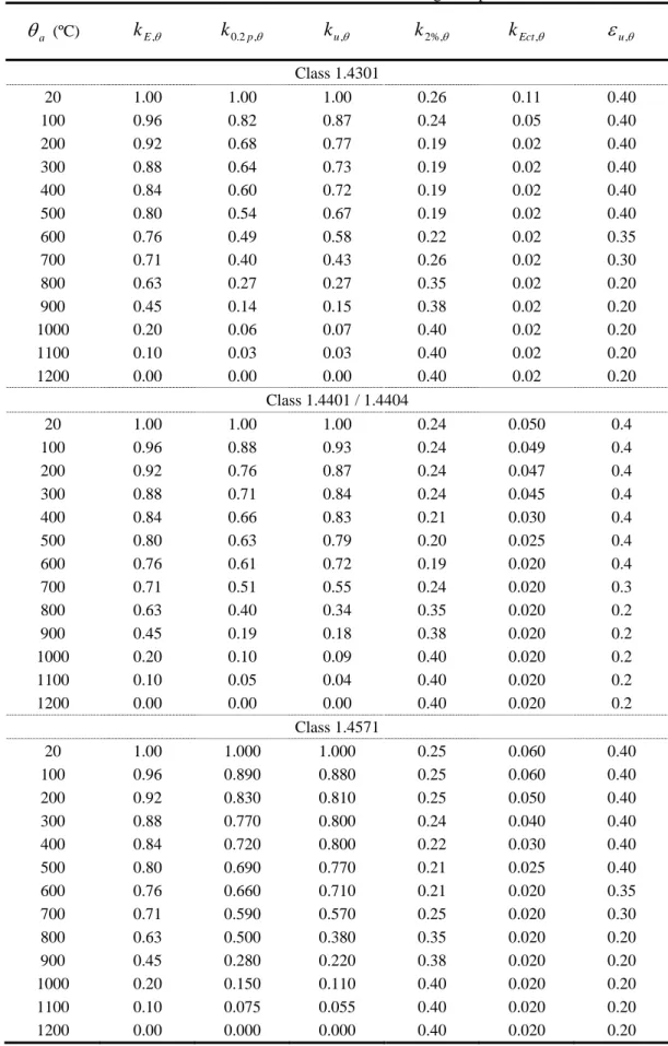
Table 2.3 – Reduction factors for the stress-strain relationship in the austenitic
stainless steels 1.4301, 1.4401, 1.4404 and 1.4571 at high temperatures. 18
Table 2.4 – Reduction factors for the stress-strain relationship in the stainless steel
1.4003 and 1.4462 at high temperatures. 19
Table 2.5 – Nominal values of the yield strength and the ultimate tensile strength at ambient temperatures for flat and long products of carbon steel grades (CEN,
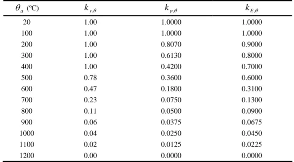
2004a). 23 Table 2.6 – Expressions to determine the stress-strain relationship of the carbon
steel at high temperatures. 24
Table 2.7 – Reduction factors of the carbon steel stress-strain relationship subject
to high temperatures. 26
Chapter 3. Numerical analysis
Table 3.1 – Position of the studied different stocky elements in this thesis. 53
Table 3.2 – Results with and without the initial rotation. 56
Table 3.3 – Results for the hollow section. 60
Behaviour of stainless steel structures in case of fire
xxxviii
Chapter 4. Prescribed design rules for structural elements
Table 4.1 – Factor used for the cross-section classification. 66
Table 4.2 – Imperfection factor and limiting slenderness. 68
Table 4.3 – Coefficients for determining the elastic critical moment. 72
Table 4.4 – Non-dimensional slenderness values for LTB of the cases presented. 79 Table 4.5 – Non-dimensional slenderness values for LTB of the cases presented
at 600 ºC. 99
Table 4.6 – Comparison between the several LTB proposals. 101
Table 4.7 – Cases studied for the LTB of carbon steel beams. 102
Table 4.8 – Comparison between ENV 1993-1-1 and EN 1993-1-1 formulae. 104
Table 4.9 – Correction factors for LTB of carbon steel elements at room
temperature. 105
Table 4.10 – Selection of LTB curve for the general case. 105
Table 4.11 – Selection of LTB curve for the special case. 105
Table 4.12 – Imperfection factors for LTB curves. 105
Table 4.13 – Severity factor for the LTB of carbon steel elements in case of fire. 113 Table 4.14 – Correction factors for the LTB of carbon steel elements in case of
fire. 113
Table 4.15 – Statistical results of carbon steel beams at elevated temperatures. 118 Table 4.16 – Non-dimensional slenderness values for LTB of the cases presented
at 600 ºC. 120
Chapter 5. Design proposals for stainless steel structural elements
Table 5.1 – Cases studied for the flexural buckling at room temperature. 129
Table 5.2 – Imperfection factor. 130
Table 5.3 – Limiting slenderness value. 130
Table 5.4 – Statistical results of columns at room temperature. 133
Table 5.5 – Cases studied with uniform bending at room temperature. 136
List of tables
xxxix
Table 5.7 – Correction factors for LTB of stainless steel elements at room
temperature. 138
Table 5.8 – Statistical results of beams at room temperature. 141
Table 5.9 – Cases studied for beam-columns without LTB at room temperature. 144
Table 5.10 – Statistical results of beam-columns without LTB at room
temperature. 154
Table 5.11 – Cases studied for beam-columns with LTB at room temperature. 155
Table 5.12 – Non-dimensional slenderness values for LTB of the cases presented. 159 Table 5.13 – Statistical results of beam-columns with LTB at room temperature. 162
Table 5.14 – Cases studied for the flexural buckling at high temperatures. 163
Table 5.15 – Coefficient for determining the reduction factor. 165
Table 5.16 – Severity factor for the flexural buckling of stainless steel elements in
case of fire. 165
Table 5.17 – Statistical results of columns at elevated temperatures. 168
Table 5.18 – Cases studied with uniform bending at high temperatures. 171
Table 5.19 – Cases studied with non-uniform bending at high temperatures. 172
Table 5.20 – Severity factor for the LTB of stainless steel elements in case of fire. 173 Table 5.21 – Correction factors for LTB of stainless steel elements at high
temperatures. 174
Table 5.22 – Statistical results of beams at elevated temperatures. 177
Table 5.23 – Cases studied for beam-columns without LTB at high temperatures. 180 Table 5.24 – Statistical results of austenitic and ferritic beam-columns without
LTB at high temperatures. 191
Table 5.25 – Statistical results of duplex beam-columns without LTB at high
temperatures. 193
Table 5.26 – Cases studied for beam-columns with LTB at high temperatures. 194
Table 5.27 – Non-dimensional slenderness values for LTB of the cases presented
at 600 ºC. 196
Behaviour of stainless steel structures in case of fire
xl
Chapter 6. Thin-walled stainless steel structural elements in case of
fire
Table 6.1 –Ultimate axial compression force without residual stresses. 210
Table 6.2 – Ultimate axial compression force with local imperfections 211
Table 6.3 – Ultimate bending moment without residual stresses 214
Table 6.4 – Ultimate bending moment with only global imperfections 215
Table 6.5 – Ultimate bending moment with only local imperfections 215
Chapter 7. Global behaviour of stainless steel structures in case of
fire
Notation
xli
Notation
Roman upper case letters
A area
eff
A effective section area
) (t
Ad calculation value of the action resulting from the fire exposition
3 2 1,C ,C
C coefficient for determining M cr
Cr chromium
E modulus of elasticity, also known as Young’s modulus
0
E initial modulus of elasticity
θ ,
a
E slope of the linear elastic range at temperature θa
θ ,
ct
E slope at proof strength at temperature θa
sec
E secant modulus
t
E tangent modulus on the stress-strain relationship
G shear modulus
k
G characteristic value of the permanent actions;
H value of the g in the second branch of the stainless steel constitutive law
i
I second moment of area in axis i
t
I torsion constant
ω
I warping constant
K coefficient to determining the buckling length in beam-columns theory fi
i
K, amplification factor in axis i in case of fire
fi LT
K , amplification factor when occurring LTB in case of fire
Behaviour of stainless steel structures in case of fire
xlii
cr
L effective buckling length of the element
Rd b
M , LTB resistance bending moment
M bending moment
A
M bending moment in extremity A
B
M bending moment in extremity B
Rd t fi b
M , ,, LTB resistant bending moment in case of fire cr
M elastic critical bending moment
Ed
M design acting bending moment value
Rd fi
M , resistant bending moment in case of fire
Ed i
M , design acting bending moment value in axis i
Ed fi i
M , , design acting bending moment value in axis i in case of fire
Rk i
M , characteristic moment resistance of the critical cross-section in axis i
pl
M plastic resistant bending moment
Rd
M resistant bending moment
Safir
M ultimate bending moment obtained in the SAFIR simulations
u
M ultimate bending moment
SAFIR i ult
M , ultimate bending moment obtained in the SAFIR simulation i
Analytical i ult
M , analytical ultimate bending moment
*
M quotient between the design bending moment and the resistant bending
moment N axial force Rd t fi b
N , ,, buckling resistant axial force in case of fire Rd
b
N , buckling resistant axial force
i Rd b
N , , buckling resistant axial force in axis i
min , ,Rd
b
N minimum buckling resistant axial force Nb,Rd,i
cr
N critical axial force
i cr
Notation
xliii
Ed
N design axial force value
Ed fi
N , design axial force value in case of fire Rd
fi
N , resistant axial force in case of fire Rd
N resistant axial force
Rk
N characteristic resistance to normal force of the critical cross-section
*
N quotient between the design axial force and the resistant axial force
Ni nickel
pl
N plastic axial force
1 ,
k
Q characteristic value of the main or dominant variable action; i
eff
W , effective section modulus in axis i
i el
W , elastic section modulus in axis i
i pl
W , plastic section modulus in axis i
Roman lower case letters
c b
a ,, parameters to calculate the carbon steel stress-strain relationship at high
temperatures d
c b
a, , , parameters to calculate the approximation proposed to the stainless steel hardening rule
e d c b
a, , , , parameters to calculate the stainless steel stress-strain relationship at high temperatures
n i
a displacement after iteration i
LT
a coefficient necessary for beam-column design with LTB
b width of a cross-section
eff
b effective width of a cross-section
a
c steel specific heat
ii
c coefficient necessary for beam-column design in axis i
m
Behaviour of stainless steel structures in case of fire
xliv
mi
c , cmi,0 equivalent bending moment coefficients for beam-column formulae in axis i
mLT
c equivalent bending moment coefficients for beam-column formulae with LTB
f coefficient for accounting with non-uniform bending diagram in LTB
p
f0.2 stainless steel proof strength at 0.2% plastic strain
θ , 2 . 0 p
f stainless steel proof strength at 0.2% plastic strain at temperature θa
θ %, 2
f stress at 2% total strain at temperature θa
θ ,
p
f carbon steel proportional limit at temperature θa
fu ultimate tensile strength
fu,θ ultimate tensile strength at temperature θa
fy yield strength
fy,θ yield strength at temperature θ
g first derivative of the approximation to the hardening rule
h depth of a cross-section
c
k correction factor for non-uniform bending
k plastic strain in the definition of the hardening rule
k amplification factor θ , 2 . 0 p
k reduction factor for stainless steel proof strength at temperature θa
θ %, 2
k factor for the determination of the stainless steel yield strength at high
temperatures
θ ,
E
k reduction factor for the slope of the linear elastic range at temperature θa
θ ,
Ect
k reduction factor for the stainless steel slope at proof strength at temperature θa i
k amplification factor in axis i
LT
k amplification factor when occurring LTB
θ ,
p
k reduction factor for the carbon steel proportional limit at temperature θa
θ ,
u
k reduction factor for stainless steel ultimate tensile strength at temperature θa yy
k ,kzz,k interaction factors in beam-columns design formulae zy
θ ,
y
Notation
xlv
z
k effective length factor related to the end rotation on the plan
ω
k effective length factor related to the end warping
n total number of numerical simulations
s standard deviation t thickness of a cross-section t time v volume x longitudinal position i
x quotient between Analytical
i ult M , and SAFIR i ult M , g
z distance between the shear centre and the point of load application
j
z distance necessary for determining M cr
s
z coordinate of the shear centre
Greek upper case letters
l l ∆ thermal elongation Ed i M ,∆ moments due to the shift of the centroidal axis i
Greek lower case letters
α imperfection factor
α angle between a tangent to stress-strain relationship and horizontal direction i
α imperfection factor in axis i
LT
α imperfection factor for the LTB
β coefficient for determining χi
i M ,
β equivalent moment factor in axis i
LT M,
β equivalent moment factor when occurring LTB
GA
γ partial safety factor of the permanent actions in case of accident, which should take the unit value
Behaviour of stainless steel structures in case of fire
xlvi
1
M
γ partial safety factor at room temperature
fi M ,
γ partial safety factor in fire situation
ε strain
ε coefficient for the cross-section classification c
ε strain due to creep effect at elevated temperatures
θ
εc, stainless steel total strain at proof strength at temperature θa pl
ε plastic strain
θ
εp, carbon steel strain at the proportional limit at temperature θa res
ε strain due to residual stress
el res
ε strain due to residual stress not accounting with the material non-linearity pl
res
ε remaining strain to account the material non-linearity in the strain due to
residual stress t
ε total strain
th
ε strain due to thermal elongation
θ
εt, carbon steel limiting strain for yield strength at temperature θa
θ
εu, ultimate strain at temperature θa y
ε coefficient necessary for beam-column design with LTB
θ
εy, carbon steel yield strain at temperature θa
σ
ε strain due to stress
η coefficient to determine α
θ temperature a
θ steel temperature
λ element slenderness value
a
λ steel thermal conductivity
0
λ limiting slenderness value for dispending buckling calculations
i
λ element slenderness value in axis i
θ
Notation
xlvii
LT
λ element slenderness value for the LTB
0 ,
LT
λ limiting slenderness value for dispending LTB calculations
θ
λLT, element slenderness value for the LTB in case of fire
θ
λ element slenderness value at high temperatures
µ coefficient to determining the amplification factors k
µ average value
i
µ coefficient to determining the amplification factors k i
i
µ coefficient necessary for beam-column design in axis i
θ
µi, coefficient to determining the amplification factors Ki,fi
LT
µ coefficient to determining the amplification factor kLT θ
µLT, coefficient to determining the amplification factor KLT,fi
θ
µSafir, coefficient to determining the amplification factors Ki,fi obtained with MSafir
ν poisson’s ratio
τ stress from the hardening rule
res xy,
τ residual tangential stresses
σ stress 2 1,σ σ principal stresses on Aproximati
σ stress according to the developed approximation of the stainless steel
constitutive law res
c,
σ comparison stress of the residual stresses
3
EC
σ stress according to the stainless steel constitutive law in EC3 res
σ residual stresses
res x,
σ residual stresses in axis x
res y,
σ residual stresses in axis y
φ coefficient used in the determination of the buckling reduction factor φ angle formed by the deformed tangent of the beam and its initial position
i
Behaviour of stainless steel structures in case of fire
xlviii
θ
φi, coefficient for determining the reduction factor χi,fi LT
φ coefficient for determining the reduction factor χLT com
LT,θ,
φ coefficient for determining the reduction factor χLT,fi i
χ reduction factor for the flexural buckling in axis i
fi i,
χ reduction factor for the flexural buckling in axis i in case of fire
LT
χ reduction factor for the LTB
fi LT,
χ reduction factor for the LTB in case of fire
mod , , fi
LT
χ modified reduction factor for the LTB in non-uniform bending in case of fire
mod ,
LT
χ modified reduction factor for the LTB in non-uniform bending
min
χ minimum of the reduction factor χi
fi
min,
χ minimum of the reduction factor χi,fi
ψ quotient between the moments in the extremities
1 , 1
ψ combination coefficient associated to the main or dominant variable action; i,
2
ψ combination coefficient associated to the remaining variable actions; i
ψ quotient between the moments in the extremities in axis i
Vectors
[ ]
D matrix of Hooke in linear elasticity{ }
εres matrix of residual strains(
x, y and xy)
{ }
σres matrix of residual stresses(
x, y and xy)
Sub-script
i axis y or z
Notation
xlix
Abbreviations
CEN European Committee for Standardisation (in French Comité Européen de
Normalisation)
EC3 Eurocode 3
GMNIA Geometrically and materially non-linear imperfect analysis
LTB Lateral torsional buckling
Chapter 1
Introduction
Behaviour of stainless steel structures in case of fire 2 Chapter 1. Introduction 1.1 General considerations 1.2 Objectives 1.3 Thesis outline
Chapter 1. Introduction
3
Chapter 1. Introduction
1.1 General considerations
The use of stainless steel for structural purposes has been limited to projects with high architectural value, where the innovative character of the adopted solutions is intended to add value to the structure. The high initial cost of stainless steel, coupled with: (i) limited design rules, (ii) reduced number of available sections and (iii) lack of knowledge on the additional benefits of its use as a structural material, are some of the reasons that force designers to avoid its use. However, more accurate analysis points to a good performance of stainless steel when compared against conventional carbon steel (Gardner, 2005; Estrada
. al
et , 2007; Cruise, 2007).
The most important advantage of stainless steels is their corrosion resistance, however, their aesthetic appearance, ease of maintenance, durability and the low life-cycle costs are also valuable characteristics. Engineers often disregard these advantages of stainless steel due to its high initial cost, although scenarios of short-term savings leading to bigger long-term expenditure are numerous throughout the construction industry. Moreover, greater importance is being given to total life costing because of high maintenance, shut-down, demolition and parts replacement costs. Experience has shown that the benefits of a long life with low maintenance and repair requirements more than compensates for the higher purchase cost of stainless steel.
With the objective of eliminating technical obstacles to trade and harmonization of technical specifications in the Member States of the European Community, the European Commission took the initiative to establish a set of harmonized technical rules for the design of construction works. These technical rules were prepared and published by the European Committee for Standardization (CEN) that conducted to the development of the Structural Eurocodes (CEN, 2005a). The Eurocodes consist of a group of ten parts dedicated to: basis and actions required in the design of structures; particular rules and recommendations necessary for structures made of different materials (concrete, steel, timber, masonry and aluminium), geotechnical design and design for earthquake
Behaviour of stainless steel structures in case of fire
4
resistance. From these set of rules one is dedicated exclusively to the design of steel structures, designated as Eurocode 3 (EC3).
Codes of practice are aimed at providing safe, competitive and, as far as possible, simple procedures for the design of structures. Drafting and implementing a consistent set of structural Eurocodes involving a large number of groups of experts is naturally a recursive task where each part must reflect the scientific advances and design options of all other related parts.
Regarding fire structural resistance, simplified design rules provided by those codes of practice, are of the utmost importance to designers that do not always have access to applications dealing with advanced calculation methods.
Axially loaded carbon steel columns in fire have been studied by Franssen .
al
et (1995; 1996; 1998) who proposed a procedure for the safety evaluation of columns subjected to high temperatures, later adopted by part 1-2 of EC3 (CEN, 2005b).
Vila Real etal. (2001; 2003b) analyzed the problem of lateral torsional buckling (LTB) of beams in case of fire, and equally proposed an expression adopted in part 1-2 of EC3 (CEN, 2005b). This proposal was developed for the case of simply supported beams with fork supports and uniform bending diagrams, being the most severe situation. The safety evaluation, of steel structural elements, subjected to axial compression and bending, is made through interaction formulae that combine the compression and bending resistances. For beam-columns in case of fire, part 1-2 of the EC3, named also
as EN 1993-1-2 (CEN, 2005b) adopts the format given in part 1-1 of EC3
of 1992 (CEN, 1992), replacing: i) the yield stress and the modulus of elasticity for its values at high temperatures; ii) the buckling reduction factors for flexural buckling and LTB in fire; and also, when no LTB exists, iii) the interaction curves, resulted from
studies by Talamona etal. (1995; 1997). The final version of part 1-1
of EC3, EN 1993-1-1 (CEN, 2005a), introduced several changes in the cold design formulae for carbon steel beam-columns when compared with the previous versions of EC3 (CEN, 1992). Two new methods, which are the result of the work carried out by two working groups who followed different approaches (Boissonnade etal., 2006), are proposed in the EN version of EC3 (CEN, 2005a). Following these modifications, some studies (Vila Real etal., 2003d; Lopes etal., 2003; 2004; Lopes, 2003; Knobloch