Joanna Ptaszkowska
Numerical modelling
of masonry vaults strengthened
with transversal diaphragms
DECLARATION
Name: Joanna Ptaszkowska Email: [email protected]
Title of the Msc Dissertation:
Numerical modelling of masonry vaults strengthened with transversal diaphragms.
Supervisor(s): Daniel Oliveira
Year: 2013
I hereby declare that all information in this document has been obtained and presented in accordance with academic rules and ethical conduct. I also declare that, as required by these rules and conduct, I have fully cited and referenced all material and results that are not original to this work.
I hereby declare that the MSc Consortium responsible for the Advanced Masters in Structural Analysis of Monuments and Historical Constructions is allowed to store and make available electronically the present MSc Dissertation.
University: Universidade do Minho Date: 12/07/2013
Signature:
Numerical modelling of masonry vaults strengthened with transversal diaphragms
ACKNOWLEDGEMENTS
Presented work was developed within the framework of SAHC Erasmus Mundus Masters Course (www.msc-sahc.org) at University of Minho under supervision of Prof. Daniel Oliveira.
This thesis is a result of a dissertation proposal made by the author. Therefore, I am highly grateful Prof. Daniel Oliveira that he decided to take me under his supervision although the subject was not connected with his proposals. Thanks to his guidance and ideas the thesis developed in an interesting direction giving me chance to work on some topics that greatly increased my personal skills in the field of numerical modelling and widen my knowledge about the masonry structures. I would like to thank him for his time spent on discussing even the smallest issues of the thesis that at the end made the work attractive for me, and hopefully for others also. His enthusiasm and many suggestion helped me to deal with all the problems that I came across during the thesis writing.
I want to thank Paolo Girardello for sharing his experimental results obtained during his PhD in Università degli Studi di Brescia, Italy, which concluded in thesis: ‘Rinforzo di volte in muratura con materiali compositi innovativi’ (Strengthening of masonry vaults with innovative composite materials). His experimental work was the base for the my numerical models and strengthening solution, and thus for the whole thesis. Many thanks also to Bahman Ghiassi, PhD student at UMINHO, who was a great help while I was having my first steps in numerical modelling.
I would like to thank the European Union for giving me the chance to be a part of the Advanced Masters in Structural Analysis of Monuments and Historical Construction (SAHC) program. Specially, many thanks for financial support throughout the Erasmus Mundus Scholarship without which it would be impossible for me to be a part of the SAHC Master.
I would like to express my gratitude to Prof. Pere Roca, Prof. Luca Pelà and other professors at the Universitat Politècnica de Catalunya (UPC) and all incoming teachers for their effort to make our stay in Barcelona productive and memorable. Special thanks to UPC professors for help in official matters, while making the integrated project on Church in Hospital Sant Pau.
I am grateful to my friends and colleagues from Barcelona for their friendship, amusing work-time in the study room. Specially thanks for great time after classes which made the whole stay more unforgettable. I would like to thank all friends that were with me in Guimarães, without them the thesis writing would be much less funny. Thanks to them time spent in UMINHO was an enormous pleasure.
I cannot be more thankful to my family for their support and encouragement during the months of master. Also, many thanks to my boyfriend for inspiring me to apply for the master and later for making my life so much easier while working on assignments and thesis. Thanks to him I could be more focused on self-development in field of historical construction than I could imagine.
Numerical modelling of masonry vaults strengthened with transversal diaphragms
ABSTRACT
Masonry vaults and arches are one of main structural elements present in most of historical constructions. Due to the impact of time, load and other construction features their strength capacity decreases making them more vulnerable to failure. Deflection and dislocation of units create internal condition of higher stress state, which in consequence can lead to premature collapse. That is why, to maintain the role of the vaults and arches and prevent them from failure, strengthening is needed. During the strengthening evaluation it cannot be forgotten that historical constructions are part of our cultural heritage and engineers are required to follow the conservation doctrine of minimum intervention. This condition involves detailed studies before proceeding with application of strengthening. Within, this framework, numerical modelling appears as a very useful method to define the accuracy of the intervention before it is applied.
The main objective of this thesis is numerical study of masonry arches and vaults strengthened by means of extrados stiffening diaphragms. Preparation and validation of numerical models was done according to an experimental arch tested by Paolo Girardello at University of Brescia, Italy. Based on the experimental parameters and geometry, two numerical models, built up on macro- and micro- approaches, were constructed in DIANA Finite Element Analysis program. The purpose of making two models was comparison of structural response of each one to monotonic, incremental load and conclude on usefulness of macro-modelling approach for masonry arch-type constructions.
Further, analysis of the efficiency of strengthening techniques throughout the non-linear analysis on both model types was performed. As a final step, parametric study of the strengthening technique was done for the macro-model of the arch. Data comparison between analyzed reinforced models was conducted and final conclusions on which parameter affects the structural response are stated.
Numerical modelling of masonry vaults strengthened with transversal diaphragms
RESUMO
Os arcos e as abóbadas de alvenaria são dos principais elementos estruturais presentes na maioria das construções históricas. Devido às ações atuantes, efeito dapassagem do tempo e outrosaspetos da construção, a sua capacidade resistente diminui progressivamente tornando-os mais vulneráveis do ponto de vista estrutural. Movimentos parciais de partes dos arcos podem criar condições para um maior estado de tensão, que por consequência pode levar ao colapso prematuro. Neste sentido, o reforço surge como uma possibilidade para manter a função estrutural das abóbadas e arcos e impedi-los de ruir. Durante a avaliação da necessidade de reforço, não pode ser esquecido que as construções históricas são parte da nossa herança cultural e que aos técnicos se pede que observem a doutrina da intervenção mínima na conservação. Esta condição envolve estudos detalhados antes de se prosseguir com a aplicação de reforço. Dentro deste quadro, a modelação numérica aparece como um método muito útil para definir a precisão da intervenção antes desta se realizar.
O principal objetivo desta tese consiste no estudo numérico de arcos e abóbadas de alvenaria reforçadas por meio de diafragmas rígidos colocados no extradorso. A preparação e validação dos modelos numéricos foi feita de acordo com os resultados de um arco testado experimentalmente por Paolo Girardello da Universidade de Brescia, Itália. Com base nos parâmetros experimentais e geometria, foram construídosdois modelos numéricos no software DIANA, seguindo as estratégias de macro e micro-modelação. O propósito de fazer dois modelos foi permitir a comparação da resposta estrutural de cada modelo para carga monotónica incremental e concluir sobre a utilidade de uma abordagem baseada em macro-modelos para construções de alvenariado tipo arco.Posteriormente, foi analisada a eficácia da técnica de reforço através da realização de análises não lineares em ambos os tipos de modelo. Foi ainda feito o estudo paramétrico do reforço usando macro-modelo do arco. Finalmente, fez-se a comparação dosresultados entre os modelos reforçados analisados e discutem-se em detalheos resultados obtidos.
Numerical modelling of masonry vaults strengthened with transversal diaphragms
ABSTRAKT
Sklepienia i łuki murowane są jednym z głównych elementów strukturalnych w wielu konstrukcjach historycznych. W związku z upływem czasu, działania obciążeń oraz różnych cech konstrukcji nośność obiektów historycznych maleje sprawiając, iż stają się bardziej podatne na uszkodzenie. Ugięcia i przemieszczenia fragmentów konstrukcji tworzą podwyższony stan naprężenia, który w konsekwencji może prowadzić do przedwczesnego zniszczenia. Aby zachować strukturalną funkcję łuków i sklepień oraz uchronić je przed zniszczeniem niezbędne jest zastosowanie wzmocnień konstrukcyjnych. Podczas oceny sposobu wzmacniania nie można zapomnieć, że obiekty historyczne należą do naszego dziedzictwa kulturowego i inżynierowe są
zobowiązani do przestrzegania doktryn konserwatorskich, w których minimum interwencji jest jednym z głównych kryteriów. Aby dostosować się do wymogów doktryn przed zastosowaniem jakiegokolwiek wzmocnienia szczegółowa analiza konstrukcji jest niezbędna. Dlatego też, analiza numeryczna wydaje się być najlepszym sposobem na określenie skuteczności wzmocnienia przed zastosowaniem go.
Niniejsza praca magisterska pod tytułem: „Analiza numeryczna sklepień murowanych wzmocnionych membraną usztywniającą”, ma na celu analizę zwiększenia nośności ceglanych łuków i sklepień poprzez zastosowanie usztywniających membran zamocowanych po stronie grzbietowej łuku.
Modele numeryczne stworzone na potrzeby niniejszego pracowania zostały przygotowane na podstawie łuków doświadczalnych testowanych przez Paolo Girardello na Universytecie w Brescia, Włochy. Bazując na geometrii i właściwościach materiałów otrzymanych z testów doświadczalnych dwa modele numeryczne, makro- i mikro-, zostały wykonane w programie DIANA Finite Element Analysis. Intencją utworzenia dwóch modeli było porównanie zachowania każdego z nich pod wpływem jednostajnie wzrastającego obciążenia oraz wyciągnięcie wniosków na temat użyteczności makro-modelu do analizy murowanych zakrzywionych konstrukcji.
Następnym krokiem była analiza efektywności proponowanej techniki wzmacniania przy użyciu nieliniowej analizy wykonanej na obu modelach. Końcową czynnością, było przeprowadzenie analizy parametrycznej wzmocnienia wykonanej na makro-modelu. Ostatnim etapem przeprowadzonego badania jest porównanie otrzymanych wyników z wszystkich wykorzystanych modeli oraz ostateczny wniosek, który z parametrów konstrukcji wpływa w największym stopniu na odpowiedź strukturalną konstrukcji.
Numerical modelling of masonry vaults strengthened with transversal diaphragms
TABLE OF CONTENTS
Chapter 1 INTRODUCTION ... 1
1.1. Background ... 1
1.2. Motivation and objective of the thesis... 3
1.3. Thesis organization... 4
Chapter 2 MASONRY ARCHES AND VAULTS – OVERVIEW ... 7
2.1. Historical background on masonry arches and vaults ... 7
2.2. Structural behaviour... 8
2.3. Strengthening techniques ... 10
2.3.1. Steel ties (external/internal) ... 11
2.3.2. Reinforced concrete shells ... 12
2.3.3. Suspensions of arches and vaults ... 13
2.3.4. Grout injections; rebuilding... 14
2.3.5. Fiber Reinforced Polymers (FRP) ... 16
2.3.6. Innovative composite materials (SRP, SRG and TRM) ... 19
2.3.7. Extrados stiffening elements ... 21
Chapter 3 NUMERICAL MODELLING OF ARCHES AND VAULTS ... 25
3.2. Types of analysis of masonry structures ... 26
3.2.1. Limit analysis method ... 26
3.2.2. Linear elastic analysis ... 27
3.2.3. Non-linear analysis ... 28
3.2.4. Finite element representation ... 29
Chapter 4 MODELLING OF REFERENCE ARCH ... 31
4.1. Experimental model and data collection ... 31
4.2. Macro-model of the reference arch ... 33
4.2.1. Finite element model adopted ... 33
4.2.2. Numerical results ... 35
4.3. Micro-model ... 38
4.3.1. Adopted numerical model... 38
4.3.2. Modelling results ... 40
4.4. Comparison of the numerical models ... 43
Chapter 5 MODELLING OF AN ARCH STRENGTHENED WITH STIFFENING DIAFRAGMS ... 45
5.1. Macro-model of strengthened arch ... 45
5.1.1. Numerical model adopted ... 45
5.1.2. Numerical results of the macro-modelling analysis ... 48
5.1.3. Results summary ... 53
5.2. Micro-model of strengthened arch ... 55
5.2.1. Characteristics of the micro-model ... 55
5.3. Comparison of models ... 59
Chapter 6 PARAMETRIC STUDY OF THE DIAPHRAGM’S ROLE ... 61
6.1. Model selection ... 61
6.2. Arch strengthened with thicker extrados stiffening diaphragm (s_arch_2) ... 62
6.3. Strengthened arch with extrados stiffening diaphragm of better masonry quality (s_arch_3) ... 63
6.4. Strengthened arch with higher mortar properties (s_arch_4) ... 65
6.5. Comparison of results ... 67
Chapter 7 FINAL REMARKS ... 71
7.1. Main conclusions ... 71
7.2. Further research ... 72
Numerical modelling of masonry vaults strengthened with transversal diaphragms
LIST OF FIGURES
Fig. 2.1. Line of thrust and failure mechanism of an unstrengthened masonry arch subjected to
vertical load applied to: a) middle of the span; b) ¼ of the arch span [4]. ... 9
Fig. 2.2. Thrust line of an arch strengthened with use of FRP at: a) extrados; b) intrados [4]. ... 10
Fig. 2.3. Location of steel ties counteracting the thrust from the arch: a) under the intrados; b) above the extrados [5]. ... 11
Fig. 2.4. Strengthening of an arch with use of reinforced concrete shell applied in the extrados [6]. ... 12
Fig. 2.5. Use of suspension solution in Basilica of Saint Francisco di Assisi [11]. ... 13
Fig. 2.6. Examples of application of injection into a masonry arch [12]. ... 14
Fig. 2.7. Reconstruction of a part of a soldier masonry vault of the St. Fermo Church in Verona, Italy [14]. ... 15
Fig. 2.8. Comparison between different types of FRP regarding used fiber and mechanical properties of each [20]. ... 17
Fig. 2.9. Constitutive laws and stress-strain distribution in section [4]. ... 17
Fig. 2.10. Formulation of the “tear” mechanism of the detachment of the FRP from the masonry arch [4]. ... 18
Fig. 2.11. Sliding mechanism between mortar and brick and formulation of the shear resistance of the section [4]. ... 19
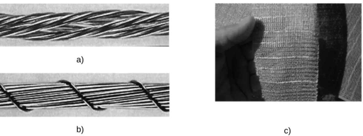
Fig. 2.12. Reinforcing component of the SRP/SRG technique: a) steel cord made by twisting two-wire strands around three two-wire strand; b) steel cord with 12 two-wires wrapped by one two-wire; c) cords held together by two knit yarns made from polyester [25]. ... 20
Fig. 2.13. Basalt-Textile applied to a) a specimen; b) an experimental arch [27]. ... 21
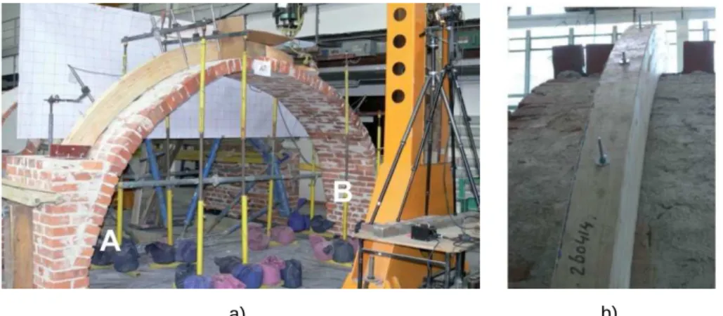
Fig. 2.14. a) View of the experimental arch strengthened with glulam beam; b) Detail of anchor of the glulam beam-arch [30]. ... 22
Fig. 2.15. a) Lightweight rib cross section; b) Continuous ribs placed over a vault [29]. ... 23
Fig. 2.16. a) Vault with extrados stiffening diaphragms; b) damage of diaphragm reinforced with SRP [28]. ... 23
Fig. 3.1. Linear elastic analysis of the Crypt of the Güell Colony in Barcelona, [37]. ... 28
Fig. 3.2.Modelling strategies for masonry structures: a) detailed micro-modelling; b) simplified micro-modelling; c) macro-modelling [36]... 29
Fig. 4.1. Experimental arch: a) scheme of the arch with position of load application; b) real view of the setup of the construction, [31]. ... 32
Fig. 4.2. Unreinforced arch: a) scheme of the arch with position plastic hinges; b) real view of the location of plastic hinges, [31]. ... 33
Fig. 4.3. Geometry of the arch model. ... 34
Fig. 4.4. Eight-nodded quadrilateral element mesh applied to the model. ... 34
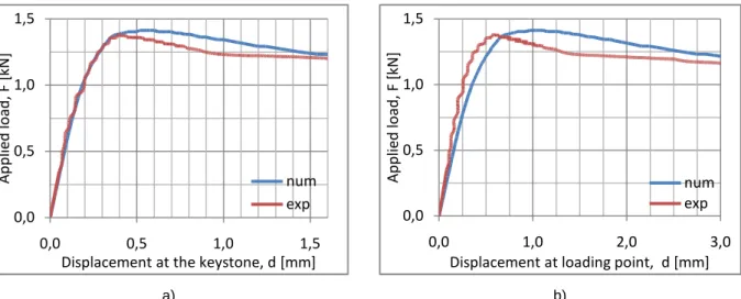
Fig. 4.6. Comparison between experimental and numerical arch results presented on load -
displacement curve for a) the keystone, b) loading point. ... 36
Fig. 4.7. Numerical sequence of hinges formation for the unstrengthened masonry arch defined as principal strains imitating crack appearance. ... 38
Fig. 4.8. Identification of the hinges’ formation on the load-displacement curve. ... 38
Fig. 4.9. Composite interface model, [40]. ... 39
Fig. 4.10. Meshing type use in the model: a) general view, b) detail of the unit. ... 40
Fig. 4.11.Comparison of results between experimental and numerical arch presented on load - displacement curve for a) the keystone, b) loading point. ... 41
Fig. 4.12. Sequence of hinge formation on a deformed model with distributed principal strains. .. 42
Fig. 4.13. Detail of joints opening caused by each hinge for the load step corresponding with formation of the last hinge. ... 42
Fig. 4.14. Identification of the plastic hinges formation on the load-displacement curve. ... 43
Fig. 5.1. Geometry of the strengthened arch model. ... 46
Fig. 5.2. General view on the adopted mesh. ... 47
Fig. 5.3. Detailed view on the mesh elements applied for particular model elements. ... 48
Fig. 5.4.Comparison of results between unstrengthened and strengthened arch presented on load - displacement curve for a) the keystone, b) loading point. ... 49
Fig. 5.5. Deformation and hinge location of the numerical arch (s_arch_1) under the peak load (2,15kN). ... 50
Fig. 5.6.Comparison of results between unstrengthened and strengthened arch presented on load - displacement curve for a) the keystone, b) loading point. ... 51
Fig. 5.7. Numerical sequence of hinges formation for the strengthened masonry arch defined as principal strains imitating crack appearance. ... 52
Fig. 5.8.Comparison of results between unstrengthened and strengthened arch presented on load - displacement curve for a) the keystone, b) loading point. ... 53
Fig. 5.9. Deformation of the arch and distribution of principal tensile strains under the force 1,72kN for model: a) without interface (s_arch_1); b) with interface (s_arch). ... 54
Fig. 5.10. Geometry of the strengthened arch with used material types for each element. ... 55
Fig. 5.11. Meshing type use in the model: a) general view, b) detail of the unit-diaphragm connection. ... 55
Fig. 5.12.Comparison of results between unstrengthened and strengthened arch presented on load - displacement curve for a) the keystone, b) loading point ... 57
Fig. 5.13. Deformed arch with distribution of principal tensile strains for steps of a-c) hinge formation, d) ultimate load. ... 58
Fig. 5.14. Deformed arch with distribution of principal tensile stresses for steps of a-c) hinge formation, d) ultimate load. ... 58
Fig. 6.1.Comparison of results between unstrengthened and strengthened arch presented on load - displacement curve for a) the keystone, b) loading point. ... 62
Numerical modelling of masonry vaults strengthened with transversal diaphragms
Fig. 6.2. Deformation and distribution of principal tensile strains for model s_arch_2: a) under peak load; b) in moment of final displacement. ... 63 Fig. 6.3.Comparison of results between unstrengthened and strengthened arch presented on
load - displacement curve for a) the keystone, b) loading point. ... 64 Fig. 6.4. Deformation and distribution of principal tensile strains for model s_arch_3: a) under
peak load; b) in moment of final displacement. ... 65 Fig. 6.5.Comparison of results between unstrengthened and strengthened arch presented on
load - displacement curve for a) the keystone, b) loading point. ... 66 Fig. 6.6. Deformation and distribution of principal tensile strains for model s_arch_4: a) under
peak load; b) in moment of final displacement. ... 67 Fig. 6.7.Comparison of results between all types of analyzed arches presented on load -
Numerical modelling of masonry vaults strengthened with transversal diaphragms
LIST OF TABLES
Table 4.1. Mechanical properties of materials (CoV in brackets), [29]. ... 32
Table 4.2. Results of the experimental test, [29]. ... 33
Table 4.3. Elastic and inelastic properties of the masonry ... 35
Table 4.4. Comparison of results of experimental and numerical tests. ... 36
Table 4.5. Elastic properties of the masonry and interface. ... 39
Table 4.6. Inelastic properties of the interface. ... 39
Table 4.7. Comparison of results of experimental and numerical tests. ... 41
Table 4.8. Comparison of results of experimental and numerical tests. ... 43
Table 5.1. Elastic and inelastic properties of the masonry diaphragm ... 46
Table 5.2. Elastic properties of the masonry and interface. ... 48
Table 5.3. Inelastic properties of the masonry and interface ... 48
Table 5.4. Comparison of results for unstrengthened and strengthened (perfect bond) models. .. 49
Table 5.5. Comparison of results for unstrengthened and strengthened (with interface) models. 51 Table 5.6. Comparison of results for unstrengthened and strengthened models. ... 53
Table 5.7. Elastic properties of the masonry and interface. ... 56
Table 5.8. Inelastic properties of the masonry and interface ... 56
Table 5.9. Comparison of results for unstrengthened and strengthened models. ... 57
Table 6.1. Comparison of results for models of different properties. ... 63
Table 6.2. Material properties of masonry of extrados stiffening diaphragm. ... 64
Table 6.3. Comparison of results for models of different properties. ... 65
Table 6.4. Properties of the interface element (s_arch_4). ... 66
Table 6.5. Comparison of results for models of different properties. ... 66
Chapter 1
INTRODUCTION
1.
1.1.
Background
Among various structural elements of historical constructions masonry arches and vaults deserve special attention. Thanks to them construction of some most beautiful and spectaculars buildings (like gothic cathedral) was possible. This was achievable due to remarkable properties of arches and vaults, which is compression state in which they work. During centuries, arches and vaults gave opportunity to create buildings on enormous scale with use of materials of low or almost null tensile strength, i.e. like masonry.
Historical constructions, over their lifetime, have undergone significant environmental influence by means of excessive load, water and wind erosion, settlements etc. Therefore, the current condition of many monuments and important buildings is recognized as endangered by collapse. That is why, the field of structural strengthening of existing constructions grows every year. Historical constructions are subjected to constantly acting ageing processes, thus it is of high importance to develop means of sustaining their existence and, if possible, restore their primary resistance of load capacity and stability.
Structural strengthening of historical construction is a delicate matter. It has to be preceded by careful studies of the nature of the building: its structural response to differential load
Introduction
combinations, origins of the problems and, most of all, it’s expected behaviour after strengthening intervention. That is why, every building has to investigated and treated as an individual case to address its needs best. It cannot be forgotten that a historical building is an object of great value form the cultural point of view, which leads to applying methods that will not alter its aesthetic side, as well as will allow to keep its function or give new one.
Over decades many preservation works have been done and a significant number of strengthening techniques was developed. Unfortunately, not all of them were successful as it happened that the intervention sometimes destroyed the cultural value of the building. To prevent repetition of poor restoration practice, the International Council on Monuments and Sites (ICOMOS) formulated some ground guidelines to help organizing work done on historical constructions so that monuments would be approached in a better way.
A body in ICOMOS, ISCARSAH (International Scientific Committee for Analysis and Restoration of Structures of Architectural Heritage) created a set of principles and recommendations aimed in ensuring rational methods of analysis and repair of historical construction appropriate to the cultural context. It recognizes that conventional calculation techniques and legal codes or standards oriented to the design of modern constructions may be difficult to apply, or even inapplicable, to historical structures. Additionally, recommendations state the importance of a scientific, multidisciplinary approach involving historical investigation, inspection, monitoring and structural modelling and analysis [1].
The principle of ISCARSAH state several important issues that have to be taken into consideration, always when approaching a historical construction. Authenticity of the structure with respect to the cultural context of the monument has to be preserved. The value and authenticity of architectural heritage cannot be assessed by fixed criteria because the respect due to each culture requires that its physical heritage is considered within the cultural context it belongs.
The value of each historic building is not only in the appearance of individual elements, but also in the integrity of all its components as a unique product of the specific building technology of its time and place. Thus, removal of the inner structures retaining only a façade does not satisfy conservation criteria.
The peculiarity of heritage structures, with their complex history, requires the organization of studies and analysis in steps. Condition survey, identification of the causes of damage and decay, choice of the remedial measures and control of the efficiency of the interventions has to be done. Nevertheless, no action should be undertaken without ascertaining the likely benefit and harm to the architectural heritage. Furthermore, where urgent safeguard measures are necessary to avoid imminent collapse they should avoid permanent alteration to the fabric.
Numerical modelling of masonry vaults strengthened with transversal diaphragms
A full understanding of the structural behaviour and material characteristics is essential for any conservation and restoration project. It is essential on the original and earlier states of the structure, on the techniques that were used and construction methods, on subsequent changes, on the phenomena that have occurred, and, finally, on its present state. Diagnosis of the state of the structure should be based on quantitative approaches (structural analysis, monitoring, in situ-laboratory tests, historical/ archaeological research) and qualitative ones, like direct observation of the damages and decays occurring in the building. A proper diagnosis has to be prepared aiming on determining the causes of existing problems.
After recognition of the origins of the damage and decay, a plan for remedial works and controls should be created. As mentioned, the plan should be addressed to fix the cause of the problems, rather than just symptoms. Only indispensable actions should be held to maintain architectural integrity of the constructions. Above all, rule of minimum intervention should be applied to show the respect towards historical and cultural significance, as well as to existing materials and structure.
Overall, while designing an intervention plan it has to be remembered that the above mentioned aims can be fulfilled by respecting some key orientations[1]:
• Safety evaluation and requirements; understanding of actions;
• Compatibility between original and newly added materials;
• Least intrusiveness;
• Durability;
• Reversibility;
• Controllability.
With the help of the ISCARSAH guidelines and with experience of the people working on restoration of a particular historical construction, the goal of maintaining world heritage, with its cultural, not altered value, should be achieved.
1.2.
Motivation and objective of the thesis
The thesis is focused on analysis of strengthening techniques applicable to masonry arches and vaults present in historical construction. Elongation of life of structural elements in present construction is crucial, as many of historical buildings are defined as Cultural Heritage and cannot be alter in any way that will destroy its original meaning or function. Therefore, responsible strengthening of historical constructions is an important issue in modern restoration practice. With the presence of new composite materials many traditional reinforcement methods were disregarded as not enough efficient in comparison with new technologies. The main aim of this
Introduction
thesis is to carefully analyse one type of traditional strengthening technique, use of extrados stiffening elements made of masonry (sometimes called ribs).
Further, a comparison research is done on two types of numerical approaches: macro- and micro-modelling. In vast variety of researches done on masonry arches and vaults, the way to represent complex behaviour of an arch is done with use of micro-models. This is due to the fact, that representation of mortar joints as interfaces is of high importance to credibly reproduce arch behaviour. What is more, macro-modelling approach is considered to be able to realistically replicate only global behaviour of a structure, rather than some local phenomenon. Nevertheless, it has a big advantage that should be taken into account, which is higher and quicker feasibility of the model.
Regarding above mentioned issues, the thesis will try to simulate structural response of a masonry arch with the use of macro-modelling approach and to compare obtained results with the developed micro-model. This way a new numerical tool for analysis of masonry arches might be worth considering in the future analyses.
Detailed goals of the thesis are defined as follow:
• To compare and to evaluate the applicability and limitation of the finite element numerical methods applied to a masonry arch and to accurately demonstrate the behaviour of the structure;
• To define the reliability of the macro-modelling approach used for masonry arches in comparison with the micro-modelling method;
• To identify the effectiveness of the strengthening technique by means of numerical modelling and parametric study.
1.3.
Thesis organization
The Master thesis is organized into seven chapters, of which the introduction chapter is considered as the first one.
Chapter two presents a brief introduction to the history of use of arches in construction. Description of the structural behaviour of arches and simple vaults are also presented. Main body of the chapter is devoted to variety of strengthening techniques applicable to historical constructions.
Chapter three contains some crucial issues that have to be defined prior to any analysis. Main types of analysis are listed and explained, with focus on applicability to masonry arches and vaults and advantages and drawbacks of each.
Numerical modelling of masonry vaults strengthened with transversal diaphragms
First part of chapter four describes the modelling of reference arch of the case study that is developed in the paper. Firstly, information about experimental tests is provided, with specifications of the geometry and materials of the masonry arch, as well as the type of strengthening applied. Further, two type of numerical models of experimental arch created in DIANA software are presented. Macro- and micro-model will be developed in order to define the differences in behaviour of each of model. The aim is to identify if a macro-model can represent complex behaviour of and arch as well as a micro-model. Characteristics of macro- and simplified micro-model are presented: material properties, geometry, mesh and constitutive laws used for each element.
Chapter five is focused on analysis of the strengthening technique for both numerical models of reference arch. Macro-model of strengthened arch will be considered in two manners. Firstly, the model will be built up as a continuous element (without distinction between arch and the reinforcing constituent). The whole model will be constructed of masonry treated as a composite material of uniform and homogenized properties. The result of analysis will allow to define the static behaviour and the influence of the reinforcement in terms of ultimate load capacity and stiffness. Secondly, an interface will be applied to the macro-model of strengthened arch to identify the difference in the structural behaviour between this and the first, fully continuous model. As the last step, the simplified micro-model of the experimental arch will be strengthened with extrados stiffening diaphragms built as an element of homogenized material properties. An interface between original arch and new element will be introduced to create a model closer to reality.
To fully exploit the utility of the macro-model, parametric study is presented in chapter six. Three modifications are applied to the reinforcement. Change in thickness and material properties allows to get differential results which help to conclude on the effectiveness of the strengthening technique.
Final remark, presented in chapter seven, are focused on comparison of behaviour and results between different types of numerical model of the same element. Furthermore, the conclusion on the efficiency of the strengthening technique is formulated based on observation of results from both numerical models. Results of the parametric study are presented with final statement on the influencing parameters. The chapter also includes a short review of opportunities for further research in the field of strengthening with extrados stiffening diaphragms.
Introduction
Chapter 2
MASONRY ARCHES AND VAULTS –
OVERVIEW
2.
Masonry structures are in general among constructions that are hardest to analyze. From point of view of the material parameters to the complexity of the construction it is never easy to define the state of a structure. Masonry, as a material, presents heterogeneous properties and its behaviour should not be considered as linear, especially under tensile stress state. Moreover, past builders and architects showed endless imagination in the manner they created new shapes and construction details which hinder the analysis of the structural performance of many buildings. Nevertheless, humanity should be thankful for their creativity because often, their innovative solution gave us the opportunity to admire their work.
2.1.
Historical background on masonry arches and vaults
Vaulted constructions, suggested by nature itself, come after the use of shapes which are stable by only mobilizing compressive – arches and vaults. Used already by ancient civilizations in Mesopotamia, it was intensively exploited by Romans and has prevailed as the main roofing approach for large constructions up to the 19th-20th c. technological revolution [2].
True vaulting poses significant construction challenges, as the need for expensive and time-demanding shores and centering. Some cultures (Greek Mycenaean, Sumerian, Sasanian Persia etc.) skipped these difficulties by resorting to false vaults and arches built as sequence of
self-Masonry arches and vaults – overview
stable cantilevers. The technique affords only very limited spans to the cost of a millennium BC significant rise and high consumption of material.
True arch and vault construction has been achieved by the following means:
• Using true centering and shores (normally made of wood);
• Using earth or rubble fillings and mounds instead of centering;
• Using smart construction procedures avoiding or reducing the need for centering.
Younger civilizations (like Romans and the Byzantine Empire) noticed that use of arches and vaults allow to significantly enlarge the span between structural elements, and better transition of the forces towards the foundations. Therefore, its use allowed the construction of more spacious buildings of thinner structural elements, thus it reduced the cost of the erection of a structure. From the Roman structures, to the Gothic ones, with each year the use of arches and vaults was exceeded up till modern times. The invention of combined steel-concrete material solved problems of tensile resistance and allowed construction of big span buildings without the need for arches.
2.2.
Structural behaviour
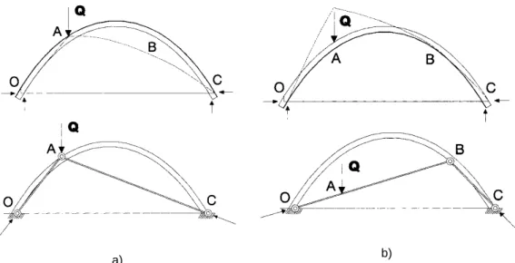
Masonry arches and vaults owe their popularity in historical constructions to the remarkable property that they posses - state of compression in which they work. Nevertheless, their stability and safety highly depend on the mechanical properties of the masonry constituents as well as on the structures geometry. Due to the fact that masonry has negligible tensile strength, the safety condition of an arch is conditioned on the thrust line lying within the borders of each section of the arch itself. If the thrust line becomes tangent at any point of the arch section, formation of plastic hinge will occur. A hinge enhance further arch deformation, by material crushing in the compressed side of the section. This changes the structural behaviour of an arch and increases the probability of development of sufficient number of hinges (minimum four) to transform an arch into a mechanism and to cause its collapse [2], see Fig. 2.1.
Numerical modelling of masonry vaults strengthened with transversal diaphragms
b)
Fig. 2.1. Line of thrust and failure mechanism of an unstrengthened masonry arch subjected to vertical load applied to: a) middle of the span; b) ¼ of the arch span [4].
Strengthening of a masonry arch can significantly change its structural behaviour as well as increase its ultimate load capacity (as proven in the literature mentioned along the following chapters). Nonetheless, the structural response of a strengthened arch varies depending on the type of the intervention applied. Some techniques prevent formation of plastic hinges (like FRP or SRG), other increase load-carrying capacity but do not alter the failure mechanism ( i.e. lateral spandrel walls). Therefore, each strengthening solution has to be considered individually depending on the result that should be obtained.
The most significant impact on the collapse mechanism of a strengthened arch makes use of continuous reinforcing system, like in the case of FRP, SRP or SRG. As shown in the Fig. 2.2 presence of FRP strips or SRG layer, applied at the intrados or at the extrados of the vaults alters the mechanism of formation of the plastic hinges, because the reinforcement (fibers and steel cords) can bear the stresses occurring at the tensed edges. In those sections (which are in combined axial and bending stresses), as for concrete structures, the resistance depends on the masonry compression strength and on the fiber or steel tensile strength. In any case, the resistant mechanism is substantially enhanced.
In the case of extrados strengthening the line of thrust can fall outside the lower edge of the vault without any structural collapse (Fig. 2.2a). For the case of a vertical load applied to 1/4 of the span, the hinge formation in the extrados is prevented. As a consequence, the vault becomes an isostatic structure (it is a three hinges arch) consisting of two curved beams strengthened on their upper sides. Such a scheme allows one to obtain the stress parameters in every section of the structure by simple geometrical and equilibrium relationships.
In the case of a structure strengthened at the intrados, although the resultant static scheme is similar to the one adopted in the previous case, note that the distribution of the stress parameters is very different (Fig. 2.2b). First, the line of thrust falls outside the upper edge of the structure and the fibers prevent the hinge formation close to the point of application of the load. As a consequence, the external load is no longer in a nodal position, so the trend of the stress parameters along the vault changes. In particular, comparing the two cases, the flexural moment changes its sign and the shear stress at the springers is reduced [4].
Masonry arches and vaults – overview
a)
Fig. 2.2. Thrust line of an arch strengthened with use of FRP at:
2.3.
Strengthening techniques
During decades of rehabilitation of
developed. With the progress of technology
therefore nowadays there is a wide range of interventions that can be used. Choosing the right method is a complicated process in which many factors have to be taken into consideration. The designer has to remember about factors such as:
• Cultural value of the structure, which will define w many times the surface of the intr
• Toward what loading condition the strengthening is pointed out: seismic performance, upgrading load-carrying capacity or stabilisation of damaged construction;
• Reversibility of the technique and its interferenc limited due to the cultural value of the structure;
• Cost estimation is an important factor, as some techniques require high costs;
• Feasibility and efficiency
In the following pages a short presentation of traditional and innovative strengthening techniques will be presented focusing on the properties of each
will be pointed to show that all methods have to historical construction.
b) . Thrust line of an arch strengthened with use of FRP at:
a) extrados; b) intrados [4].
Strengthening techniques
rehabilitation of historical constructions many strengthening techniques were developed. With the progress of technology, more sophisticated approaches
therefore nowadays there is a wide range of interventions that can be used. Choosing the right licated process in which many factors have to be taken into consideration. The designer has to remember about factors such as:
Cultural value of the structure, which will define where the intervention can be applied (i.e. many times the surface of the intrados in covered with painting, mosaics etc.);
Toward what loading condition the strengthening is pointed out: seismic performance, carrying capacity or stabilisation of damaged construction;
Reversibility of the technique and its interference into the original element, which is often limited due to the cultural value of the structure;
Cost estimation is an important factor, as some techniques require high costs; and efficiency of the method in the particular conditions.
lowing pages a short presentation of traditional and innovative strengthening techniques will be presented focusing on the properties of each one. The advantages and drawbacks of will be pointed to show that all methods have to be carefully considered before applying to any
many strengthening techniques were s were develop, therefore nowadays there is a wide range of interventions that can be used. Choosing the right licated process in which many factors have to be taken into consideration. The
ere the intervention can be applied (i.e. ados in covered with painting, mosaics etc.);
Toward what loading condition the strengthening is pointed out: seismic performance, carrying capacity or stabilisation of damaged construction;
e into the original element, which is often
Cost estimation is an important factor, as some techniques require high costs;
lowing pages a short presentation of traditional and innovative strengthening techniques . The advantages and drawbacks of them before applying to any
2.3.1. Steel ties (external/internal)
Steel ties, located above the extrados o strengthening method. This relatively easy stress condition that comes from thrust.
abutment of the arches that, consequently, are subjected to crack formation that decreases structural capacity of the construction.
Use of ties influences the stiffness and stability of the construction. T a) Decrease the displacement of the abutment;
b) Decrease the formation of cracks in the arches and supporting walls; c) Help in distribution of internal forces, even in the
Accurate performance of the tie, in
introduced in and by the tie (see scheme at
needed, is primary pretensioning of the tie to the correct value corresponding with the compression capacity of the wall
Unsuitable force introduced by the tie to the wall can lead to further cracking of the
Therefore, it is of high importance to determine the correct value before applying the solution. Furthermore, it is worth considering the way of anchoring the tie to the wall and its thermal deformations as it might affect the efficiency of t
An important issue while strengtheni
of the ties and accurate preparation of the wall. One of the rules used while tying historical constructions is transition of the forces at possibly big area as it is connected with low
compressive strength of the masonry wall.
a)
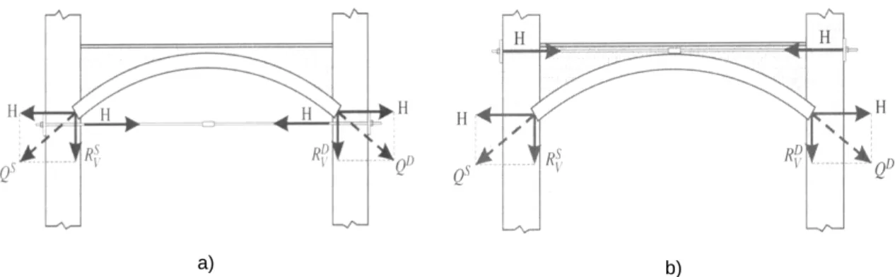
Fig. 2.3. Location of steel ties counteracting the thrust from the arch: a) under the intrados; b) above the extrados
Numerical modelling of masonry vaults strengthened with transversal diaphragms
(external/internal)
bove the extrados or under the intrados are one of the strengthening method. This relatively easy-to-make technique helps to redistribut
stress condition that comes from thrust. Too high value of thrust creates outward movement of the abutment of the arches that, consequently, are subjected to crack formation that decreases
construction.
s influences the stiffness and stability of the construction. Ties have following effects Decrease the displacement of the abutment;
Decrease the formation of cracks in the arches and supporting walls; Help in distribution of internal forces, even in the case of further damage.
Accurate performance of the tie, in a historical construction, is connected with the internal force (see scheme at Fig. 2.3). A good solution, for obtaining th
needed, is primary pretensioning of the tie to the correct value corresponding with the compression capacity of the wall [6].
Unsuitable force introduced by the tie to the wall can lead to further cracking of the
Therefore, it is of high importance to determine the correct value before applying the solution. worth considering the way of anchoring the tie to the wall and its thermal
fect the efficiency of the tie.
An important issue while strengthening with the use of steel ties is the correct
of the ties and accurate preparation of the wall. One of the rules used while tying historical of the forces at possibly big area as it is connected with low
ve strength of the masonry wall.
b) . Location of steel ties counteracting the thrust from the arch:
a) under the intrados; b) above the extrados [5].
thened with transversal diaphragms
the most widely used make technique helps to redistribute unfavourable Too high value of thrust creates outward movement of the abutment of the arches that, consequently, are subjected to crack formation that decreases
ies have following effects:
case of further damage.
historical construction, is connected with the internal force . A good solution, for obtaining the exact force needed, is primary pretensioning of the tie to the correct value corresponding with the
Unsuitable force introduced by the tie to the wall can lead to further cracking of the construction. Therefore, it is of high importance to determine the correct value before applying the solution. worth considering the way of anchoring the tie to the wall and its thermal
correct strategic positioning of the ties and accurate preparation of the wall. One of the rules used while tying historical of the forces at possibly big area as it is connected with low punctual
Masonry arches and vaults – overview
Traditional steel tying has a big disadvantage, namely, the
through the anchors visible on the facades and/or through the ties themselves. Nowadays, this issue is often solved by the use of steel
presents a set of advantages like: easier access to the wall from inside, shorter installation time and lower cost. Another modern solution
materials, as explained in [8].
2.3.2. Reinforced concrete shells
Reinforced concrete shells is a good strengthening solution idea is to create a covering surface anchored
from deformed masonry vault [9]. Because of paintings or frescos masonry element is suspended controversial from the conservation
strengthening vaults of large spans. However, it present set of important issues that have to discussed. How to anchor properly the masonry vault if there is limited information about the st of the sections? Also, because the suspension is made in several points problems with shear stresses occurring in those places have to solved
solution can be seen in Fig. 2.4.
Fig. 2.4. Strengthening of an arch with use of reinforced concrete shell applied in the extrados
The design of the reinforced concrete shells has to
quickest way of application in the extrados of the arch/vault is by shotcrete. Shotcrete undergoes placement and compaction at the same time due to the force with which it is projected from the nozzle. It has two type of consistency before application, therefore it can be distinguished as wet mix and dry-mix versions .It can be impacted onto any type or shape of surface, inclu
or overhead areas [10]. The decision which
is of significant importance and has to be individually defined,
a big disadvantage, namely, they alter the visual aspect
through the anchors visible on the facades and/or through the ties themselves. Nowadays, this en solved by the use of steel ties glued to the masonry wall [7]. This modern solution set of advantages like: easier access to the wall from inside, shorter installation time
Another modern solution regarding tying is use of ties made of compos
oncrete shells
Reinforced concrete shells is a good strengthening solution especially for vaults of big span. Its covering surface anchored to perimetric walls, that will take the structural role
.
paintings or frescos frequently present in the intrados of arches and vaults the masonry element is suspended from the reinforced concrete shell. This method, quite controversial from the conservation point of view, is one of the few techniques which can help in strengthening vaults of large spans. However, it present set of important issues that have to
. How to anchor properly the masonry vault if there is limited information about the st of the sections? Also, because the suspension is made in several points problems with shear stresses occurring in those places have to solved [6]. Sample application of this intervention
. Strengthening of an arch with use of reinforced concrete shell applied in the extrados
The design of the reinforced concrete shells has to be done regarding the typical procedure. The the extrados of the arch/vault is by shotcrete. Shotcrete undergoes placement and compaction at the same time due to the force with which it is projected from the wo type of consistency before application, therefore it can be distinguished as wet
It can be impacted onto any type or shape of surface, inclu The decision which concrete application method use (wet
has to be individually defined, depending on the possibilities and y alter the visual aspect of the buildings through the anchors visible on the facades and/or through the ties themselves. Nowadays, this This modern solution set of advantages like: easier access to the wall from inside, shorter installation time regarding tying is use of ties made of composite
specially for vaults of big span. Its perimetric walls, that will take the structural role
in the intrados of arches and vaults the the reinforced concrete shell. This method, quite point of view, is one of the few techniques which can help in strengthening vaults of large spans. However, it present set of important issues that have to be . How to anchor properly the masonry vault if there is limited information about the state of the sections? Also, because the suspension is made in several points problems with shear Sample application of this intervention
. Strengthening of an arch with use of reinforced concrete shell applied in the extrados [6].
be done regarding the typical procedure. The the extrados of the arch/vault is by shotcrete. Shotcrete undergoes placement and compaction at the same time due to the force with which it is projected from the wo type of consistency before application, therefore it can be distinguished as
wet-It can be impacted onto any type or shape of surface, including vertical (wet-mix or dry-mix) depending on the possibilities and
Numerical modelling of masonry vaults strengthened with transversal diaphragms
needs of the construction site. Therefore, it cannot be generally classify which of the method is better.
Previous to use of reinforced concrete shells a deep examination of the applicability and effects on the construction has to performed. This technique might solve mechanical problems occurring in the vault, however it might cause other ones like non-reversibility of method and incompatibility of structural elements. Thanks to in-detail studies aforementioned difficulties might be avoided. Nevertheless, decision to use reinforced concrete shells has to reconsidered taking into account all the possible benefits of the strengthening, but even more, focusing on undesirable effects that the method can bring. If the benefits are insufficient in comparison to possible problems change of strengthening concept is an reasonable approach.
2.3.3. Suspensions of arches and vaults
Suspensions of arches and vaults is a technique based on creation of new load carrying construction that will take the structural role from the masonry element. In particular, this technique is used when other measures are inadequate and propping beneath the element cannot be a solution. The suspension structure can be made of timber elements of significant capacity. Wood is light and can easily adjust to the environmental conditions above the masonry vaults. It consists in adding an active connection (sometime provided with dissipative elements) of the original structure with an upper structure (sometimes the roof structure) carrying part of the load, in order to stabilize and relive load from the original structure.
One of the most famous examples of strengthening with this method is strengthening of the vaults in the Basilica of Saint Francisco di Assisi [11]. Here the solution was complex and the engineering created a set of glulam ribs strengthened with AFRP to precisely imitate the shape of the vault as shown in the Fig. 2.5.
a) b)
Masonry arches and vaults – overview
The important factor in effectiveness of the solution is creating a precise curvature of the ribs. Specially, this is important when ribs are going to
curvature can be avoided if the ribs are made of solid ti
connected with lower quality of the wood and, thus, smaller construction.
As used in the Basilica of Saint Francisco di Assisi
application of FRP to increase the load carrying capacity and limit the size of the ribs. worth considering the use of lightweight, spatial steel trusses as the suspending construction main concern of this technique is
problem of shear stresses occurring in the masonry
2.3.4. Grout injections; rebuilding
Apart from the range of techniques focused on strictly structural strengthening of construction restoring the original properties of the material pays
actions an element might regain its mechanical properties and,
need to apply structural interventions. Nevertheless, in general, those measures are conside more like a complementary works rather than as a way to strengthen a construction.
2.3.4.1. Grout injections
The aim of injection is to restore the uniformity of the material as well as order to protect the inside of the masonry from har
a delicate matter requiring many preliminary actions. Many factors have to be considered, among which the choice of the grout composition
Fig. 2.6 presents a sample of strengthening solution with the use of injection.
Fig. 2.6. Examples of
There are three main methods of injection regarding arches and vaults how the injection is made. Namely,
The important factor in effectiveness of the solution is creating a precise curvature of the ribs. Specially, this is important when ribs are going to be made of glulam. High level of detail in the curvature can be avoided if the ribs are made of solid timber prepared in-situ. Nevertheless, this is connected with lower quality of the wood and, thus, smaller assurance of the safety of the
As used in the Basilica of Saint Francisco di Assisi, a good improvement of the method is RP to increase the load carrying capacity and limit the size of the ribs.
use of lightweight, spatial steel trusses as the suspending construction main concern of this technique is the need for sufficient area of adherence as well as solving the problem of shear stresses occurring in the masonry-rib interface.
; rebuilding
Apart from the range of techniques focused on strictly structural strengthening of construction of the material pays a great role in reconstruction. Thanks to those actions an element might regain its mechanical properties and, consequently, there
need to apply structural interventions. Nevertheless, in general, those measures are conside works rather than as a way to strengthen a construction.
is to restore the uniformity of the material as well as to seal all cavities in order to protect the inside of the masonry from harmful agent, like humidity. The act of injection is a delicate matter requiring many preliminary actions. Many factors have to be considered, among grout composition and its consistency are of the highest importance. presents a sample of strengthening solution with the use of injection.
. Examples of application of injection into a masonry arch [12].
There are three main methods of injection regarding arches and vaults. They depend on the way Namely, the following methods can be defined [13]:
The important factor in effectiveness of the solution is creating a precise curvature of the ribs. made of glulam. High level of detail in the situ. Nevertheless, this is assurance of the safety of the
a good improvement of the method is RP to increase the load carrying capacity and limit the size of the ribs. It is also use of lightweight, spatial steel trusses as the suspending construction. The ence as well as solving the
Apart from the range of techniques focused on strictly structural strengthening of constructions, . Thanks to those , there might be no need to apply structural interventions. Nevertheless, in general, those measures are considered
works rather than as a way to strengthen a construction.
seal all cavities in mful agent, like humidity. The act of injection is a delicate matter requiring many preliminary actions. Many factors have to be considered, among and its consistency are of the highest importance.
Numerical modelling of masonry vaults strengthened with transversal diaphragms
2) Pressure injection- grout is injected with the use of a special unit;
3) Vacuum injection – grout is inserted inside the masonry thanks to underpressure created by a vacuum unit.
As mentioned before, the main aim of injection is to uniform the masonry element in its section so that it would perform like a full material. As well, to protect the material inside. However, there are exceptions that injection is used as a singular strengthening solutions. Though, it has to be remembered that injection does not solve the problems of the construction, therefore it can be used just if the destruction process is stabilized. Moreover, grout injection is an highly intrusive and non-reversible action, therefore it application has to be carefully reconsidered as if this kind of actions ascertain benefits higher than the cost of non-reversibility [12].
Main types of grouts are connected with the type of base matrix. They can be mineral (cementicious, gypsum, lime-gypsum) and based on polymers, i.e. epoxy [14]. Mineral grout are in general cheaper and compatible with existing masonry construction, nevertheless the properties of the old and new material have to be checked a priori to application. Epoxy grouts allow to create a substance of required properties, however possible incompatibility has to be taken into consideration.
2.3.4.2. Rebuilding
Rebuilding is a concept that can be applied to walls, but also to arches and vaults. The idea is to recover the original structural response by means of restoring continuity along a cracked area by remaking it [9]. In this technique, use of materials similar in composition, shape, dimensions, stiffness and strength, to those employed in the original wall is preferable, to pursue compatibility and homogeneity in the global behaviour. This method is more a repair than strengthening of the element, therefore an important matter is to remove the origins of the problems.
Fig. 2.7 presents an example of the rebuilding works done on a vault in St. Fermo Church in Verona, Italy [14]. Here the rebuilding was just a first step of intervention aiming at repair of a deformed vault. Further works were connected with strengthening the vault with use of FRP strips.
Fig. 2.7. Reconstruction of a part of a soldier masonry vault of the St. Fermo Church in Verona, Italy [14].
Masonry arches and vaults – overview
2.3.5. Fiber Reinforced Polymers (FRP)
Among the materials used to repair or to upgrade existing historical and modern structures, there has been a significant interest in the use of fiber-reinforced polymer (FRP) composites, either in the form of externally bonded or near-surface mounted reinforcements. This interest in FRP is connected with some features that it possesses, like: low weight, corrosion immunity, high tensile strength, adaptability to curved surfaces, and ease of application, which makes it attractive to be used in repair or strengthening works. Several studies were performed to define the properties of arches strengthened with this technique: [16], [17], [18], [19]. In all of them FRP present a set of advantages, but it has some drawbacks, among which are: high cost and low fire resistance, durability uncertainty and possible mechanical and physical incompatibilities. As well, brittle failure of FRP is a feature that has to be carefully considered when applying FRP to a masonry element. Continuous fiber-reinforced materials with polymeric matrix (FRP) can be considered as composite, heterogeneous, and anisotropic materials with a prevalent linear elastic behaviour up to failure. Composites for structural strengthening are available in several geometries from laminates used for strengthening of members with regular surface to bi-directional fabrics easily adaptable to the shape of the member to be strengthened. Those materials are also suitable for applications where the aesthetic of the original structures needs to be preserved (buildings of historic or artistic interest) or where strengthening with traditional techniques cannot be effectively employed.
There are three main types of FRP used in civil engineering, which depend on the type of fiber used. Those are: carbon, glass and aramid fiber, which differ in the mechanical properties (Fig. 2.8). Recently an increased interest in use of basalt fibers was noticeable, due to its similar properties to glass fibers in terms of ductility and load capacity (according to [20]) and its much lower cost in comparison with carbon or aramid fibers, thus seem accurate for low-cost interventions. Furthermore, basalt fibers are in-toxic, no environmental restrictions apply to it. Additionally, because of its thermal isolating properties, is suited for use as fire-protection application.
FRP can vary also in the type of matrix used: epoxy of mortar based. FRPs come with several type of fabrics: bars, sheets and laminates. With such big assortment of fabrics it is essential to define the type most suitable for the need.
Numerical modelling of masonry vaults strengthened with transversal diaphragms
Fig. 2.8. Comparison between different types of FRP regarding used fiber and mechanical properties of each [20].
As explained in Chapter 2.2 the application of the strengthening material modifies the static behaviour of the arch by inhibiting the formation of the fourth plastic hinge. Therefore, the collapse of the structure is due to other mechanisms, which are dependent on the limits of strength of the constituent materials (original vault and reinforcement) and on the structural interactions of them at the local level.
Because a design criterion taking into account the premature failure of the masonry against the reinforcement has been adopted, the following possible mechanisms of collapse are considered:
1. Crushing of the masonry
A first formulation of the model for the evaluation of the ultimate strength of strengthened sections under combined compressive and bending stresses, similar to the one assumed for RC structures, was developed by Triantafillou in [21]. As for the constitutive laws of the materials, a linear elastic behaviour was adopted in the model for the reinforcement whereas a rectangular stress-block law was considered for the masonry (Fig. 2.9). The state of stress in a section of the vaults can easily be obtained by relations of equilibrium.
Masonry arches and vaults – overview
2. Detachment of the adhesion system
Reinforcement’s detachment from the support is due to the presence of a component perpendicular to the plane of the tensed fibers. This effect provokes a mechanism that could be defined as a ‘‘tear’’. Fig. 2.10 shows a portion AB of the laminate, having length ds and radius of
curvature R, whose internal tensile force per unit width T is assumed constant; dN is the
component normal to the segment AB that is responsible for the phenomenon. By using simple geometric relationships, both the arch equation and the tensile stress of the fiber are known and it is possible to evaluate in any section the normal component dN.
Fig. 2.10. Formulation of the “tear” mechanism of the detachment of the FRP from the masonry arch [4].
The simplest way to deal with this phenomenon was to equal the perpendicular tensile strength of masonry (measured through pull-off tests) to the calculated normal component dN/ds. Therefore, it
is possible to find backwards which is the maximum acceptable tensile force T that can be assigned to the reinforcement and, consequently, the maximum external loads (e.g. see[15], [22]). Another possible solution to this problem is use of anchors to increase the resistance against the detachment of the FRP system [24].
3. Mortar-brick sliding due to shear stresses
Such a mechanism is caused by the presence of the shear stress component in each section. The mathematical model describing the resistant mechanism is still under calibration by experimental tests. It is supposed that the sliding resistance is caused by two main components, R due to the masonry and R to the FRP laminate. As for the masonry contribution, a friction model following the Coulomb law is assumed and a dowel action effect is considered for the reinforcement. Fig. 2.11 shows a scheme of a section of the vault in the failure conditions. The experimental tests have allowed analysis of the above mentioned mechanisms and proposal of simplified mathematical models.
![Fig. 2.5. Use of suspension solution in Basilica of Saint Francisco di Assisi [11].](https://thumb-eu.123doks.com/thumbv2/123dok_br/17765537.836230/33.892.141.774.834.1051/fig-use-suspension-solution-basilica-saint-francisco-assisi.webp)
![Fig. 2.16. a) Vault with extrados stiffening diaphragms; b) damage of diaphragm reinforced with SRP [28]](https://thumb-eu.123doks.com/thumbv2/123dok_br/17765537.836230/43.892.139.760.698.976/fig-vault-extrados-stiffening-diaphragms-damage-diaphragm-reinforced.webp)
![Fig. 3.1. Linear elastic analysis of the Crypt of the Güell Colony in Barcelona, [37]](https://thumb-eu.123doks.com/thumbv2/123dok_br/17765537.836230/48.892.168.694.343.525/fig-linear-elastic-analysis-crypt-güell-colony-barcelona.webp)