Physical and geometrical non-linear behavior of precast
beams on elastomeric supports
Comportamento não linear físico e geométrico de vigas
pré-moldadas sobre apoios elastoméricos
a Faculdade de Engenharia Civil, Universidade Federal de Uberlândia, Uberlândia, MG, Brasil.
Received: 08 Mar 2017 • Accepted: 23 Oct 2017 • Available Online: 15 Feb 2018
M. T. S. A. CARDOSO a
M. C. V. LIMA a [email protected]
Abstract
Resumo
The stability of long and slender precast beams has been associated with structural collapse during the transitory phase of construction. The inevitable deviations regarding the execution between the support cross-section and midspan aggravate the instability problem, thus causing the
beams to become even more susceptible to its effects. The focal point of this study is the numerical and behavioral evaluation of concrete beams that present geometric imperfections on elastomeric supports and analyze the influence exerted by the variables of: strength characteristics of concrete, physical non-linearity of the concrete and the compression stiffness of the bearing pad. The numerical analyses were developed on a computer program based on the finite element method (FEM). Among the principle conclusions drawn from the study, one finds that the increase
in the characteristic strength of the concrete provides the beam with a higher degree of stability, and the consideration of the physical non-linear behavior of the material did not allow the equilibrium point on the numerical model to be found in some of the cases that were evaluated. The
rotational stiffness of the pad decreases as the skew angle increases. Therefore, one needs to remember that in very critical situations, it may not be possible to find the point of equilibrium, thus leading to collapse.
Keywords: stability, bearing pad, stiffness, equilibrium, toppling.
A estabilidade lateral de vigas pré-moldadas longas e esbeltas tem sido associada a colapsos durante as fases transitórias de montagem. Os inevitáveis desvios de execução entre a seção transversal do apoio e a do meio do vão agravam e tornam mais suscetíveis os problemas de instabilidade. O objetivo deste trabalho é avaliar numericamente o comportamento de vigas de concreto que apresentam imperfeições
geomé-tricas sobre almofadas de apoio de elastômero e analisar a influência de variáveis, como: resistência característica do concreto, não linearidade
física do concreto e rigidez à compressão da almofada. As análises numéricas foram desenvolvidas em um programa computacional baseado no
Método dos Elementos Finitos. Dentre as principais conclusões, percebeu-se que o aumento da resistência característica do concreto confere à
viga maior estabilidade e que a consideração do comportamento não linear físico do material não permite encontrar uma posição de equilíbrio no
modelo numérico em alguns casos avaliados. A rigidez ao giro da almofada diminui na medida em que o ângulo de esconsidade aumenta. Deve --se ter em mente que, em situações muito críticas, pode não ser possível encontrar equilíbrio para a viga, levando ao seu colapso.
1. Introduction
Precast concrete beams, in light of the suspension equipment as well as the limitations of the transport vehicles, have presented
cross-sections with better mechanical efficiency. Furthermore,
these elements are demanded by the very forces of the transitory
phase, such as handling, along with lifting and transport. Even the
characteristics of public roads (superelevation and curves) and the
damping system of the transport vehicle can affect the stability and
the security of these beams.
When the beam is seated in its resting position on the structure over deformable supports, although without any real connection or lateral bracing, there can still occur problems related to lateral instability. In a majority of cases, the beams are supported on
elas-tomeric supports, flexible and deformable, which may not be able
to resist rigid body rotation of the beam, and in more critical situa-tions not resist toppling.
The presence of geometric imperfections on the beam, due to the
inevitable errors during concreting, prestressing or from different
heat sources during thermal curing aggravate and heighten the probability of instability problems. The beam presents, from its ini-tial conception, a curved form that is not foreseen in the project, as for example that which occurs due to the deviation of the support cross-section in relation to the midspan, and through such is more susceptible to toppling and rigid body rotation.
In the Literature, it is possible to find authors that report the occur
-rence of accidents with precast beams during the handling tran-sitory phase, which are related to the lateral instability of these elements. The studies by Tremblay & Mitchell [1], Oesterle et al. [2] and Bairán & Cladera [3] analyze the collapse of beams on deformable supports and reported that the cause was due to
insuf-ficient lateral bracing for withstanding the rigid body rotation of the
beam or to the incorrect sizing and positioning of the bearing pad support on the structure. A recent case occurred in Brazil in 2014, with the collapse of a beam on the monorail in São Paulo, which had already been positioned onto the structure.
The authors Burgoyne & Stratford [4] and Plaut & Moen [5] deal with lateral instability of precast concrete beams on deformable
supports and show that the deformability of the support influences
the equilibrium and stability of the beam. When one analyses the problem of lateral instability of concrete beams, it is necessary to
take into consideration conditions that are as close as possible to
real conditions. Hence, there are those geometric variables that are of extreme importance in the analyses.
According to Consolazio & Hamilton [6], the lateral eccentricity or geometric imperfection presented in
Figure 1, is the lateral displacement between the straight beam
and the real configuration in curved form. This lateral displace -ment can arise from deviations during prestressing and on the prestressed cables, deviations in the positioning of the molds and
during concreting as well as in heat sources, as in the different
sources of heat during thermal curing. In Figure 2, the skewness of the support is the angle formed between the longitudinal axis
of the route taken (roadway) and the central line of the support.
Mainly in prestressed beams, it is common to see a vertical curva-ture between the longitudinal axis of the beam on the support and the surface of the bearing pad support (Figure 3).
In this sense, the objective behind this study is to evaluate the
lateral stability of the AASHTO Type IV beam on FDOT Type A and FDOT Type B bearing pads, through considerations made with dif -ferent initial geometric imperfections during handling. Furthermore,
an evaluation will be made concerning the influence of the strength
characteristic of the concrete and its physical non-linearity and
stiffness to compression of the elastomeric bearing pad, keeping
in mind the partial contact loss between the beam and the support
device. Finally, the stiffness of the bearing pad to rotation is esti
-mated for the different skewness angles.
Figure 2
Skewness of the support
Source: Adapted from Consolazio & Hamilton (2007)
Figure 1
Lateral eccentricity
Source: Adapted from Consolazio & Hamilton (2007)
Figure 3
Vertical curvature of the beam
2. The AASHTO Type IV beam
on laminated bearing pads
This work conducted a numerical analysis on the ANSYS computer program [7], which is based on the Finite Elements Method. The beam section was defined as a standard AASHTO Type IV, as pre -sented in Figure 4, at 32 m in length, supported on FDOT Type A
and FDOT Type B standard bearing pads, for which the dimen -sions are presented on Table 1.
The AASHTO Type IV beam was analyzed with different initial geo -metric imperfections. The centroid position deviations of the cross-section at midspan relative to its intended position on the supports are presented on Table 2 and in
Figure 1. It started out by adopting a maximum eccentricity at the midsection of the beam in relation to the supports permitted by the PCI [8]: 1 cm for every 10 m of beam length. Analyses were also
made of the eccentricities close to field measurements as in Co -jocaru [9], and in a complementary manner, analysis was made of a very critical and unfavorable situation, where the values of 13.5 cm and 18 cm were adopted. The authors Burgoyne & Stratford [4]
recommend working with values for initial geometric imperfections
in the order of L/1000, where L is the total length of the beam. In
the Eurocode [10], it is suggested that for braced beams in the
transport and handling phase, a geometric imperfection in the or-der of L/300 is adopted.
In order to numerically represent the elastomeric bearing pads, the
decision was made to adopt the simplified model proposed and
experimentally evaluated by Harper & Consolazio [11], and dis-cussed and calibrated in Cardoso [12]. In this model, the bearing pad is considered as a rigid grill responsible for joining springs of
different stiffness when subjected to axial compression. This mod -el of grill divides the bearing pad into small rectangular regions and
for each there is associated a compression spring that is of a differ
-ent stiffness from the others. Springs were employed that worked
entirely compressed, in a way that traction requests result in no support reaction on the spring. Thus, it is possible to contemplate the partial loss of contact between the beam and bearing pad.
In the present study, the FDOT Type A and FDOT Type B bearing
pads are considered with standardized size and characteristics, for
which the stiffness when subjected to axial compression are respec
-tively 10991 kN/cm and 12512 kN/cm. Bearing pad A is designed
as a grill with 105 compression springs (7×15), and an area region
equal to 16 cm2. Bearing pad B is designed with a grill containing 135 compression springs (9×15), with an area equal to 16 cm2. Figure 5 presents the rigid grills for bearing pads A and B, and Figure 6, the distribution of the stiffness on the bearing pads A and
B. The values for stiffness to compression and the final consid -erations prepared in the numeric models are the same as those presented in Cardoso [12].
Guarantees were made to see that the nodes from the lower table of the beam coincided exactly with the nodes on the bearing pad
in accordance with the simplified model. For the beam, the three-dimensional element SOLID65 was employed and for the bearing
pad springs, the LINK180 was employed.
Under the beam on supports setup, the only loading that acts on the structure is its own weight, which was applied by the inertia
command from ANSYS [7]. In all of the analyses performed, the
geometric non-linearity was considered as being very important in lateral instability problems.
Three strength values characteristic of concrete were adopted (fck), namely: 27.5, 45 and 90 MPa. The initial concrete elasticity
Figure 4
Modified cross-section of the AASHTO Type IV beam
Source: Authors (2017)
Table 1
Dimensions and characteristics of the analyzed
bearing pads
Dimension/characteristic Bearing pad
A B
Length, L (cm) 60 60
Width, W (cm) 28 36
Height, H (cm) 4.8 6.5
Quantity of steel plates 3 4
Source: Authors (2017)
Table 2
Initial lateral eccentricities adopted
Beam Initial eccentricity (ei)
Absolute (ei) (cm) Relative (ei/L)
B1 1.0 (L/3200) 0.0003
B2 3.0 (L/1067) 0.0009
B3 3.2 (L/970) 0.0010
B4 5.0 (L/640) 0.0016
B5 6.6 (L/485) 0.0021
B6 9.0 (L/356) 0.0028
B7 13.5 (L/237) 0.0042
B8 18.0 (L/178) 0.0056
models adopted for the beam were respectively, 2936.67, 3756.59
and 5312.63 kN/cm2, with a Poisson coefficient equal to 0.2 and a specific weight of 25 kN/m3. The behavior of the concrete to compression was considered through the parabola-rectangle dia-grams, without softening.
It is of importance to emphasis here that in the pre-service
situa-tion, it is expected that the beam is not cracked. However, in prac
-tice one knows that it is possible that the beam cracks due to forc
-es arising from handling and transport until its final r-esting position.
Furthermore, even when the beam is on support bearing pads, the forces generated in the concrete due to rigid body rotation and the
toppling of the beam lead to cracking and loss in strength capacity.
Therefore, aimed at representing the strength capacity loss of the beam and the non-linear behavior of the concrete, a physical non-linear
analy-sis was performed on ANSYS [7]. The model concrete from the very
SOL-ID65 element was used. The force-deformation curve was obtained by the definition of the six points, for which the coordinates were calculated
through parametric equations that relate to the characteristic strength of the concrete and its initial or tangent elasticity module.
In order to use the model concrete on ANSYS [7], it was necessary to
define four parameters relevant to the behavior of drawn and com
-pressed concrete. The first two refer to the shear stress transferred to the open and closed crack. For these variables, the values of 0.2
and 1.0 were adopted, respectively. The two remaining parameters
are related to the cracking and crushing stress of the concrete, for which the values were defined as one tenth of the concrete
strength and (-1.0), respectively.
3. Results and discussions
3.1 Non-linear geometric analysis
Initially, a static analysis was performed that considered the geo-metric non-linearity, which is necessary to simulate the exclusive
effect of compression on the springs of the simplified model of the
bearing pads. In this analysis, the support reactions on the springs were obtained for each of the eight beams analyzed, for each of the three evaluated fck, and for each of the bearing pads under
Figure 5
Rigid grills for bearing pads A and B
Source: Authors (2017)
Rigid grill for bearing pad A Rigid grill for bearing pad B
B
B
A
B
Figure 6
Stiffness distribution
Source: Authors (2017)
Bearing pad A Bearing pad B
B
B
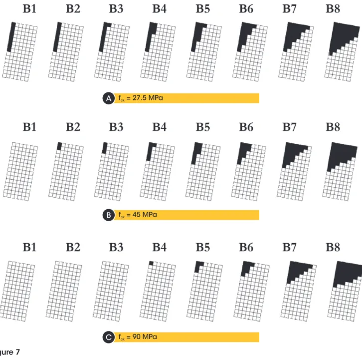
consideration. In Figures 7 and 8, the hatched area represents the region of the bearing pad on the left-hand side of the beam ( Figure 1), where there is no support reaction, or be it, the loss of
contact between the beam and the bearing pad. Note also the off -set of the result for the vertical support reaction on the elastomeric support, which deviates from the central region.
The characteristic strength of the concrete confers contact loss protection between the beam and bearing pad. The degree at which fck increased toward 90 MPa, it was noted that there was no contact loss between the beams B1, B2 and B3 and bearing pad A,
which was not verified for lower values of fck. Furthermore, for the most critical case represented by beam B8, there is a gain of 6% in
bearing pad area, which effectively resists the rigid body rotation of
the beam when compared to the hatched region in Figure 7 for the beam with fck = 27.5 MPa and fck = 90 MPa. As seen on bearing pad A, one also notes that for bearing pad B, the characteristic concrete strength of the beam plays an important role in the stability of the element in terms of toppling. Higher val-ues of fck reduce the contact loss between the beam and the
bear-ing pad, thus a greater area of the bearbear-ing pad effectively works in balancing the rigid body. Taking as a reference beam B3, for which
the initial eccentricity was considered as the limit established by the PCI [8], for fck = 27.5 MPa, one has a contact loss of 23% of the bearing pad area. Next, for fck = 45 MPa, this value is reduced
Figure 7
Contact loss on bearing pad A
Source: Authors (2017)
f = 27.5 MPack
f = 45 MPack
f = 90 MPack
B
A
B
B
B
188 IBRACON Structures and Materials Journal • 2018 • vol. 11 • nº 1 to 13%, and for fck = 90 MPa, one has a bearing pad area of 3.7%,
where there is no contact with the beam.
The maximum vertical and horizontal displacements obtained at the beam midspan are presented in Figures 9 and 10, respectively.
In a general sense, one notes that the increase in compression stiff -ness of the bearing pad, provided when using bearing pad B, led to slightly lower vertical displacements in all cases. In addition, one
notes here that the influence of concrete strength is also beneficial,
since it reduces in almost twice the value the maximum vertical dis-placements measured on the cross-section of the beam midspan. The increase in the concrete strength and the use of a bearing
pad of higher compression stiffness (bearing pad B) confer less
horizontal displacements to the beam in the middle of its span.
The effect of the initial imperfections was felt most strongly on the
horizontal displacements than on the vertical displacements. One notes from
Figure 10, that the variation of the horizontal displacement in re-gards to the variation of the initial imperfection was greater for the beams that presented higher initial lateral displacements.
3.2 Geometric and physical non-linear analysis
Numerically, in the non-linear analyses with the eight beams with fck = 27.5 MPa and with the beams B7 and B8 with fck = 45 MPa, no
Figure 8
Contact loss on bearing pad B
Source: Authors (2017)
f = 27.5 MPack
f = 45 MPack
f = 90 MPack
B
A
B
B
B
position of equilibrium was encountered. For fck = 90 MPa, results were obtained for the eight eccentricities evaluated. Once more,
the strength and stiffness of the concrete provide the structure
protection and leads to the equilibrium of the beam face through lateral stability.
The value of the support reaction with the inclusion of the physical
non-linearity of the concrete was maintained equal to that verified
by the geometric non-linear analysis, which respected the static balance condition.
Figures 11 and 12 present the maximum vertical and horizontal displacements obtained at the midspan for geometric non-linear analysis, as well as those already presented for geometric non-linear analysis.
Noted here is that the geometric and physical non-linear analysis presented displacement values close to those obtained in the geo-metric non-linear analysis. The contribution of increasing the char-acteristic strength of the concrete is also observed here, except in those cases that did not converge.
The maximum horizontal displacements measured in the non-lin-ear geometric and physical analysis were higher than those
ob-tained only in the geometric non-linear analysis. This difference
was small, but sharper when compared with the vertical displace-ments. In the same manner, the contribution of the highest charac-teristic strength of the concrete is maintained along with the most
important effect of the increase in initial geometric imperfections on
horizontal displacements than on vertical displacements.
3.3 Determining rigid body rotation for different
angles of bearing pad skewness
The AASHTO Type IV beam was analyzed with eight different ini -tial eccentricity values as presented on Table 2. Each beam was modelled with an arc, and each arc had associated to it an initial angle (a1), as presented in Figure 13.
Therefore, in regards to the global coordinate system (x and z), there arise two new axes obtained (x’ and z’) rotating the previous from a1. As a result of the support reaction on the bearing pad, this becomes displaced in respect to the axes x’ and z’, hence two bending moments are generated around these axes (Mx’ and Mz’), as presented in Figure 14.
Figure 9
Maximum vertical displacements
Source: Authors (2017)
Figure 10
Maximum horizontal displacements
Source: Authors (2017)
Figure 11
Maximum vertical displacements with physical
non-linear analysis
Source: Authors (2017)
Figure 12
Maximum horizontal displacement with physical
non-linear analysis
In order to determine the rigid body rotation in the skewed condi
-tion, the first step consists of obtaining the values of the bending moments. Through knowledge of the reactions on each spring of the simplified model, it was possible to determine the result of the
support reaction and its position on the bearing pad, and thus ob-tain the values of the bracing moments (a and b) presented in Figure 14, along with the value of the bending moments.
Following this, the rotations were determined for the axes direc-tions x’ and z’. As a result of the numerical model, the rotadirec-tions in x (ROTX) and in z (ROTZ) were obtained from ANSYS. Through these rotations, its components on the axes x’ and z’ were
calcu-lated, in order to obtain the rotation 𝜓 on the z’-axis and rotation ϕ on the x’-axis, as presented in Figure 15.
Through the values for moment and rotation on the axes x’ and z’, the resulting moment and rotation for each one of the eight beams
analysed were obtained. The stiffness to rotation under the occult
bearing pad condition was determined by producing the quotient between the resulting moment to the resulting rotation.
Figure 13
Initial angle on the beam with initial lateral
eccentricity
Source: Authors (2017)
Figure 14
Bending moments generated by the reaction
of the support on the bearing pad
Source: Authors (2017)
Figure 15
Rotations on axes x’ and z’
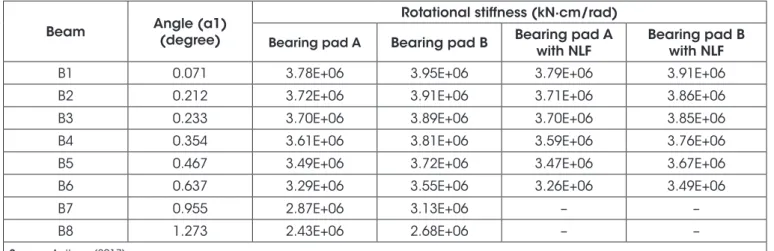
The stiffness to rotation coefficients were calculated for the eight
beams with fck = 45 MPa, through a consideration of the results ob-tained only with the geometric non-linear analysis as well as those obtained through the geometric and physical non-linear analysis. Table 3 and Figure 16 present the stiffness to rotation obtained for each beam, through the consideration or not of the physical non-linearity of the concrete. There are no results presented for beams B7 and B8, as the solution does not converge on the numerical model of these beams when the characteristic strength value of the concrete was equal to 45 MPa.
As expected, greater skewness angles lead to lower coefficient values of stiffness to bearing pad rotation. The action of the bend -ing moments in both directions of the bear-ing pad reduce the ca-pacity of the bearing pad to resist rigid body rotation of the beam and impairs lateral stability in view of the toppling of the beam. The
skewness angles considered in this work are small, since these
are due to the geometric imperfections, but in the case of curved
beams, the influence of this parameter makes this fact significant.
Noteworthy still is that Burgoyne & Stratford [5] stated in their
work that the stiffness necessary for the bearing pad can be eas
-ily calculated and should be adequately specified in the project.
However, due to the high and complex interaction of the geometric
imperfections of the beam, misalignment of supports and buckling
modes, it is desirable that one has a high safety margin (it is for this reason, the authors recommend a high safety factor) from the
stiffness to rotation given by the bearing supports. Furthermore, it is necessary to take care and stick to the centralized positioning of
the beam on the support device.
4. Conclusions
The reports of accidents and beam collapses in the Literature as-sociate these problems to the lateral instability of precast beams during the transport phase. In this manner, the study of the subject
and reaching an understanding as to the different variables that influence the behavior of the beams is of the upmost importance. The simplified model adopted in this work presented a satisfactory response to the main considerations that should be taken into ac
-count when working with beams on deformable supports. The use
of compression springs allowed for the simulation of contact loss between the beam and the elastomer, which generated a position change in the reaction of the support on the bearing pad.
The developed analyses allowed for the quantification of the com
-bined effect of the parameters, such as initial geometric imperfec
-tion, stiffness of the beam and physical non-linear effects of the
concrete. The main conclusions of this study were:
a) In the geometric non-linear analysis, the increase in the
char-acteristic strength of the concrete, and consequently the stiff -ness of the beam, led to less displacements and less areas with contact loss between the beam and the bearing pad. b) The consideration of the physical non-linear behavior of the
material (to the cracking of the concrete) showed that for the
lowest concrete strength value, the numerical model did not
find equilibrium. In terms of the intermediary concrete strength,
this also occurred to the two highest values of initial imperfec-tions, and for the highest concrete strength, it was possible to arrive at equilibrium over all values of initial imperfection.
Figure 16
Rotational stiffness × skewness angle of the
bearing pad
Source: Authors (2017)
Table 3
Rotational stiffness obtained for beams with f
ck= 45 MPa
Beam Angle (a1)
(degree)
Rotational stiffness (kN∙cm/rad)
Bearing pad A Bearing pad B Bearing pad A with NLF
Bearing pad B with NLF
B1 0.071 3.78E+06 3.95E+06 3.79E+06 3.91E+06
B2 0.212 3.72E+06 3.91E+06 3.71E+06 3.86E+06
B3 0.233 3.70E+06 3.89E+06 3.70E+06 3.85E+06
B4 0.354 3.61E+06 3.81E+06 3.59E+06 3.76E+06
B5 0.467 3.49E+06 3.72E+06 3.47E+06 3.67E+06
B6 0.637 3.29E+06 3.55E+06 3.26E+06 3.49E+06
B7 0.955 2.87E+06 3.13E+06 – –
B8 1.273 2.43E+06 2.68E+06 – –
c) The rotational stiffness of the bearing pad decreased at the
rate that the eccentricity of the beam increased, or be it, the rate at which higher bending moments began to act on both directions of the support device.
d) The presence of initial geometric imperfections generate a
skewness angle that interferes with the rotational stiffness of the
bearing pad, when considering as a reference the beam with the initial imperfection limit as established by the PCI [8]. Initial
imperfection limits that exceed this limit by five times can bring about a reduction by around 22% in the stiffness to rotation. Future analyses that take into consideration distortions on the bearing pad, the vertical curving of the beam and the effect of pos -sible forces due to wind can lead to a more profound evaluation of the problem.
This work shows the importance that should be given to geometric
imperfections of long and slender precast beams in the analyses of instability during the handling phase. It is necessary to be aware of the fact that the increase in the midspan curve, caused by the presence of initial imperfections, generates an increase in stresses on the beam that normally are not considered during the project.
These stresses can become significant when the stiffness of the
support is reduced, thus suggesting that a higher safety factor be employed by means of choosing the most adequate support bearing pad. In those more severe cases, the higher stresses can
create cracking in the concrete, thus reducing the stiffness of the
beam and causing sudden collapse.
5. Acknowledgements
The authors would like to thank CAPES for granting the scholar -ship on the Master Academic level to Maria Teresa Santos do Ama-ral Cardoso.
6. Bibliographical references
[1] Tremblay, R.; Mitchell, D. Collapse during Construction of a
Precast Girder Bridge. Journal of Performance of Construct-ed Facilities, v. 20, n. 2, 2006; p. 113-125.
[2] Oesterle, R. G.; Sheehan, M. J.; Lotfi, H. R.; Corley, W.
G.; Roller, J. J. Investigation of red mountain freeway
bridge girder colapse. Arizona Department of Transporta
-tion, Bridge Group, Skokie, Illinois. CTL Group Project No.
262291, 2007.
[3] Bairán, J. M.; Cladera, A. Collapse of a precast concrete beam for a light roof. Importance of elastomeric bearing
pads in the element’s stability. Engineering Failure Analysis,
v. 39, 2014; p. 188-199.
[4] Burgoyne, C. J.; Stratford, T. J. Lateral Instability of
long-span prestressed concrete beams on flexible bearings. The Structural Engineer, v. 79, n. 6, 2001; p. 23-26.
[5] Plaut, R. H.; Moen, C. D. Stability of unbraced concrete
beams on bearing pads including wind loading. Journal of
Structural Engineering, v. 69, 2014; p. 246-254.
[6] Consolazio, G. R.; Hamilton, H. R. Lateral bracing of long-span Florida bulb-tee-girders. Structures Research Report 2007/52290. University of Florida, Gainesville, 2007.
[7] ANSYS. v. 17.0. ANSYS, Inc.
[8] PCI Committee on Tolerances. PCI Tolerance Manual for Precast and Prestressed Concrete Construction. 1st ed. Chi-cago, IL: PCI, 2000.
[9] Cojocaru, R. Lifting analysis of precast prestressed concrete
beams, Blacksburg, VA, 2012, Dissertação (Mestrado em Engenharia Civil) – Virginia Polytechnic Institute and State
University, 94 p.
[10] Comité Européene de Normalisation. NF EN 1992 (Fran
-çais): Eurocode 2: Calcul des structures en béton. CEN,
Bruxelles, 2004.
[11] Harper, Z. S.; Consolazio, G. R. Calculation method for
quantifying axial and roll stiffnesses of rectangular
steel-reinforced elastomeric bridge bearing pads. Journal of the Transportation Research Board, n. 2331, 2013; p. 3-13. [12] Cardoso, M. T. S. A. Instabilidade lateral de vigas
pré-molda-das sobre apoios elastoméricos considerando o efeito pré-molda-das
imperfeições geométricas, Uberlândia, 2017, Dissertação (mestrado) – Faculdade de Engenharia Civil, Universidade
![Figure 1. It started out by adopting a maximum eccentricity at the midsection of the beam in relation to the supports permitted by the PCI [8]: 1 cm for every 10 m of beam length](https://thumb-eu.123doks.com/thumbv2/123dok_br/16320794.719237/3.892.546.746.170.409/figure-started-adopting-eccentricity-midsection-relation-supports-permitted.webp)